Avaya G350 Installing And Upgrading
Hide thumbs
Also See for G350:
- Maintenance manual (332 pages) ,
- Administration (306 pages) ,
- User manual (305 pages)

Related Manuals for Avaya G350


Summary of Contents for Avaya G350
- Page 1 Installing and Upgrading the Avaya G350 Media Gateway 03-300394 Issue 7 November 2009...
- Page 2 Avaya support Avaya provides a telephone number for you to use to report problems or to ask questions about your product. The support telephone number is 1-800-242-2121 in the United States. For additional support telephone numbers, see the Avaya Web site: http://www.avaya.com/support...
-
Page 3: Table Of Contents
Grounding verification ......G350 package contents ....... . - Page 4 Fastening the G350 to the wall ......Placing the G350 on a table ......
- Page 5 Step 3: Connecting to the Wide Area Network (WAN) ....Connecting a WAN to the G350 ......
- Page 6 Connecting the WAN line ......Configuring the WAN line on the G350 ..... .
- Page 7 Identifying the problem when one phone stops working ... . No power on the G350 ....... . .
- Page 8 Load firmware from a bank other than the default bank during startup . . The front panel of the Avaya MM312 media module....MM312 ports ........
- Page 9 Power cord specifications ......USB modems supported by the G350 ......
- Page 10 Contents 10 Installation and Upgrades for the Avaya G350 Media Gateway...
-
Page 11: About This Book
You can download the latest version of Installing and Upgrading the Avaya G350 Media Gateway from the Avaya Support website. You must have access to the Internet, and a copy of Acrobat Reader must be installed on your personal computer. - Page 12 An ESD warning calls attention to situations that can result in ESD damage to ELECTROSTATIC ALERT: electronic components. SECURITY ALERT: A security alert calls attention to a situation that can increase the potential for SECURITY ALERT: unauthorized use of a telecommunications system. 12 Installation and Upgrades for the Avaya G350 Media Gateway...
-
Page 13: Related Resources
Related resources Related resources For more information on the Avaya G350 Media Gateway and related features, see the following books: Title Number Overview for the Avaya G250 and Avaya G350 Media Gateways 03-300435 Quick Start for Hardware Installation: The Avaya G350 Media Gateway... -
Page 14: Technical Assistance
Call the Avaya Technical Consulting Support System at 1-800-225-7585 for help with ● feature administration and system applications. Call the Avaya National Customer Care Support Line at 1-800-242-2121 for help with ● maintenance and repair. Call Avaya Toll Fraud Intervention at 1-800-643-2353 for help with toll fraud. -
Page 15: Sending Us Comments
Westminster, CO 80234 USA Email, send your comments to: ● document@avaya.com Fax, send your comments to: ● 1-303-538-1741 Ensure that you mention the name and number of this book, Installing and Upgrading the Avaya G350 Media Gateway, 03-300394. Issue 7 November 2009... - Page 16 About this book 16 Installation and Upgrades for the Avaya G350 Media Gateway...
-
Page 17: Chapter 1: Before You Install
A crosspoint screwdriver if rack mounting or wall mounting the G350 ● If you will mount the G350 on a flat wall: screws to fasten the G350 to the wall ● If you will mount the G350 on a non-flat wall: ●... -
Page 18: Equipment Required If You Are Not Installing An S8300 Server
Obtaining the G350 serial number Look for the serial number sticker on the back of the G350 chassis. If the unit is delivered directly to the customer and you will not have phone or LAN line access from the customer site to access the http://rfa.avaya.com... -
Page 19: Checking License File And Avaya Aura™ Communication Manager Versions For A Local Survivable Processor (Lsp)
The license file requirements of the LSP should be identified in your planning documentation. Downloading CM license and authentication files to your laptop If you are installing a G350 with an S8300 Server as a primary controller, you need license and authentication files for the Communication Manager. -
Page 20: Running The Automatic Registration Tool (Art) For The Ras Ip Address
G350 and the S8300, follow this procedure twice, once for the G350 and once for the S8300. For each procedure, a script file is created and downloaded or emailed to you. You can use the installation script to automatically set up an IP address and other alarming parameters. -
Page 21: Downloading Recent Firmware
The EPW is an Excel spreadsheet from which Avaya configuration wizards automatically pull data to configure and install the S8300 Server and the G350 Media Gateway. The EPW is filled in by the customer and project manager, and should be completed before installation. -
Page 22: Site Requirements
The G350 may be installed in a 19” rack, mounted on a wall, or placed on a sturdy table. Installation instructions are provided in Installing the Avaya G350 Media Gateway on page 25. -
Page 23: G350 Package Contents
In these cases, access to the G350 Media Gateway is gained by the use of a tool (such as a lock and key) or other means of security. If you have any questions about the safety conditions, contact your project manager. -
Page 24: Unpacking And Checking Package Contents
Wear an anti-static wrist ground strap whenever handling components of an ELECTROSTATIC ALERT: Avaya G350 Media Gateway. Connect the strap to an approved ground, such as an unpainted metal surface. 2. Check the contents of the packaging against the customer order. -
Page 25: Chapter 2: Installing The Avaya G350 Media Gateway
Mounting the G350 in a rack The G350 mounts in a standard 19-inch rack. You can fasten the G350 to the rack either at the front of the G350 or at the middle. In either case, mounting brackets must be attached to the G350. -
Page 26: Brackets Without Cable Guides
Brackets without cable guides Mounting brackets without cable guides can be attached in either of the following positions: To each side of the front of the G350 for fastening the chassis to the rack at the front ● To the middle of each side panel of the G350 for fastening the chassis to the rack at the ●... -
Page 27: Brackets With Cable Guides
Brackets with cable guides You can attach the mounting bracket with cable guides to the front of the G350 on one side, as shown in the following figure. If you are fastening the chassis to the rack at the front, use the mounting bracket with cable guides as one of the two front brackets. -
Page 28: Before Mounting The G350
5. Tighten the rack mounting screws. Avoid overtightening. 6. Verify that ventilation vents are not obstructed. At this point, you have mounted the G350 chassis in the rack and are ready to insert media modules as required in the planning documentation. -
Page 29: Fastening The G350 To The Wall
Fastening the G350 to the wall Position the G350 so that its front panel is facing up. If the wall is flat, you can screw the G350 directly to the wall. If the wall is not flat, screw a plywood sheet at least ¾ in (20 mm) thick and at least 4 x 4 ft (1.2 x 1.2 m) in size, and fasten the G350 to the board. -
Page 30: Before Inserting Media Modules Into The G350 Chassis
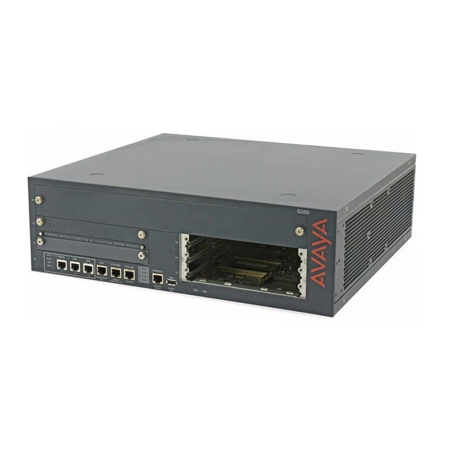
No more than three of the following media modules: ● - MM716 - MM717 Allocating slots The G350 chassis has six media module slots, marked V1, V2, V3, V4, V5, V6 (see Figure 30 Installation and Upgrades for the Avaya G350 Media Gateway... - Page 31 Note: If you install an S8300 Server that has a CWY1 module in slot V1, slot V2 cannot Note: be used. Figure 5: The G350 front panel ports and slots 16 17 10 11 12 Figure notes: 1. V6 — high-density media module slot 9.
- Page 32 Provides eight ports for connecting up to eight ISDN trunks or 16 ISDN BRI stations. MM722 V1, V2, V3, V4, V5 Provides two ports for connecting ISDN trunks. S8300 Server 2 of 2 32 Installation and Upgrades for the Avaya G350 Media Gateway...
-
Page 33: Inserting The S8300 Server
Step 2: Installing the media modules Inserting the S8300 Server The S8300 can only be inserted in slot V1 on the left side of the G350 Media Gateway. ELECTROSTATIC ALERT: Hold media modules only by the edges to avoid damage from static electricity. Do ELECTROSTATIC ALERT: not touch the top or bottom of the circuit board. - Page 34 To prevent access to electrical hazards by unauthorized personnel and to ensure DANGER: continued compliance to radiated emissions requirements, all captive screws must be securely tightened such that they cannot be loosened without the use of a tool. 34 Installation and Upgrades for the Avaya G350 Media Gateway...
-
Page 35: Inserting Media Modules
Use a screwdriver to ensure the captive screws are securely tightened to prevent damage to the equipment. 1. Position the media module before the selected bay on the front of the G350 chassis and engage both sides of the module in the interior guides. - Page 36 WARNING: After you have connected telephones to the various media modules, be sure to WARNING: add circuit protection to the lines. 36 Installation and Upgrades for the Avaya G350 Media Gateway...
-
Page 37: Attaching Ground Conductors
Installation location Select a location for the G350 installation that is close enough for use with the supplied secondary grounding conductor. If this location requirement is not met, contact a licensed electrician to install a Supplementary Ground Conductor per Article 250 of the National Electrical Code (NEC). -
Page 38: Ground Block
In these cases, access to the G350 is gained by the use of a tool (such as a lock and key) or other means of security. - Page 39 Attaching ground conductors Acceptable Water Pipe. A metal underground water pipe, at least 1/2 in (1.3 cm) in ● diameter, in direct contact with the earth for at least 10 ft (3m). The pipe must be electrically continuous (or made electrically continuous by bonding around insulated joints, plastic pipe, or plastic water meters) to the point where the protector ground wire connects.
-
Page 40: Connecting The Safety Ground
3. Cut this ground wire to the length needed to reach the approved ground. Do not coil this wire. Note: The ground block is for use with more than one G350 in the rack. If the ground Note: block is to be used, you must supply it and have it installed by an electrician. -
Page 41: Step 4: Connecting Power To The G350
After you have mounted the G350, installed the media modules, and attached grounding conductors, you can connect power to the G350. 1. Connect the power cable to the power connector on the G350 back panel. 2. Plug the power cable into an AC outlet. The G350 is now powered. - Page 42 Installing the Avaya G350 Media Gateway 42 Installation and Upgrades for the Avaya G350 Media Gateway...
-
Page 43: Chapter 3: Connecting Devices
External endpoint devices can be connected to the ports on the front panels of the installed media modules and to the fixed front panel ports. Before you connect endpoint devices, the G350 should be mounted and all media modules should be inserted. WARNING:... -
Page 44: If The Mm314 Or Mm316 Media Module Is Not Installed
Power over Ethernet (PoE) to data devices. Any data device that you want to be powered through the G350 must be connected to a network data port that is directly connected to one of the 10/100 Ethernet ports on an MM314 or MM316 media module. -
Page 45: Connecting A Computer
- 40 Ethernet 10/100 Base-T Ethernet access ports with inline Power over Ethernet (PoE) - The copper Gigabit port, labelled 51 One of the following ports on the front panel of the Avaya G350 Media Gateway chassis: ● - The ETH LAN ports... -
Page 46: Connecting A Server
Overview for the Avaya G250 and Avaya G350 Media Gateways, 03-300435. If the IP telephone will be powered through the G350, you must use a telephone that supports PoE, and the telephone will power up if and when PoE is configured on the port to which the telephone is connected. -
Page 47: Connecting The Telephone To The G350
Connecting the telephone to the G350 1. Wire a telephone to a LAN port on the G350. If the IP telephone will be powered through the G350, make sure you use a 10/100 Ethernet port on an MM314 Media Module or MM316 Media Module installed in slot V6 of the G350. -
Page 48: Connecting An Analog Telephone
54. - A LINE port on an MM714 or MM714B media module - One of the two fixed LINE ports on the G350 front panel 2. Plug the analog telephone into the telephone port. 48 Installation and Upgrades for the Avaya G350 Media Gateway... - Page 49 Step 1: Connecting data and voice devices Note: The leftmost LINE analog telephone port on the G350 front panel provides the Note: Emergency Transfer (power failure) function via a mechanical analog relay connecting it to the TRUNK port next to it. See Figure 5.
- Page 50 Connecting devices Note: Analog line ports support the following maximum distances: Note: - For phone equipment with a ringer load below 3 REN: up to 2,000 feet (609.6 m). 50 Installation and Upgrades for the Avaya G350 Media Gateway...
-
Page 51: Connecting A Dcp Telephone To An Mm312, Mm712, Or Mm717 Media Module
Connecting a DCP telephone to an MM312, MM712, or MM717 media module Note: For a full list of supported phones, see Appendix B, Supported Avaya telephones Note: in Overview for the Avaya G250 and Avaya G350 Media Gateways, 03-300435. 1. Wire a telephone port to a DCP port on the G350. -
Page 52: Connecting An Analog Trunk
● The TRUNK port on the G350 front panel. ● Note: The TRUNK analog telephone port on the G350 front panel forms a mechanical Note: analog relay with the LINE port next to it. See Figure 5. This relay can be configured to provide emergency transferred telephone service in the case of a power outage or disconnection from an external server. -
Page 53: Connecting An E1/T1 Trunk
Step 1: Connecting data and voice devices Connecting an E1/T1 trunk Connect the trunk cable to the E1/T1 port on an MM710 or MM710B media module. The SIG LED lights. Figure 19: The MM710B media module Connecting an ISDN BRI trunk Connect the trunk to any ISDN port on an MM720 or MM722 media module. -
Page 54: Connecting Devices To The Mm717 And Mm716 Media Modules
25-pair socket on the MM716 or MM717 front panel, so that the cable extends to the right of the G350. (The cable you use must be such that the connector you plug into the media module is 90° to the cable.) 2. -
Page 55: Step 2: Installing Circuit Protection
Step 2: Installing circuit protection Out-of-building installations of telephones or other standard (tip/ring) devices/terminals that connect to the Avaya G350 Media Gateway media modules require over-voltage and sneak current protection in both buildings. Field installed sneak current protectors must have a maximum current rating of 350 mA and a minimum voltage rating of 600V. -
Page 56: Step 3: Connecting To The Wide Area Network (Wan)
Step 3: Connecting to the Wide Area Network (WAN) Since the G350 contains an internal router, you can connect the G350 directly to a WAN endpoint device. You can also connect a WAN endpoint device to the G350 via an external router. -
Page 57: Connecting An E1/T1 Wan Link To The Mm340 Media Module
Connecting an Ethernet WAN link You must connect the Ethernet WAN line (DSL, firewall, etc.) to the Ethernet WAN port on the front panel of the Avaya G350 Media Gateway chassis. This port is marked ETH WAN. See Figure 5. Use a CAT5 Ethernet cable to connect the WAN line to the port. -
Page 58: Step 4: Installing The Coupled Bonding Conductor
To implement the contact closure feature, you connect an Avaya Partner Contact Closure Adjunct box to the CCA port on the G350 chassis. The adjunct box provides two contact closures that can be operated in either a “normally closed” or “normally open” state. The contact closures can control auxiliary devices such as devices that automatically lock or unlock doors or voice recording units. -
Page 59: Installing The Contact Closure
2. Note which device is connected to each relay. You will need this information for configuration. 3. Connect the Avaya Partner Contact Closure adjunct box to the CC port on the G350 front panel. Use a 24 gauge minimum telephone wire, no longer than 200 ft, with a standard four wire RJ-11 connector. - Page 60 Connecting devices 60 Installation and Upgrades for the Avaya G350 Media Gateway...
-
Page 61: Chapter 4: Connecting And Enabling A Modem For Remote Access
Connecting and enabling a modem (G350 without S8300) You can either connect a serial modem to the Console port on the G350 front panel or you can connect a USB modem to the USB port on the G350 front panel. - Page 62 3. Plug one end of the provided flat RJ-45 to RJ-45 cable into the provided DB-9 adapter. 4. Plug the RJ-45 connector at the other end of the cable into the Console port of the G350. 5. Plug the DB-9 end of the flat cable into the COM port of the laptop computer.
-
Page 63: Connecting And Enabling A Usb Modem (G350 Without S8300)
3. Plug one end of the provided flat RJ-45 to RJ-45 cable into the provided DB-9 adapter. 4. Plug the RJ-45 connector at the other end of the cable into the Console port of the G350. 5. Plug the DB-9 end of the flat cable into the COM port of the laptop computer. -
Page 64: Testing The Modem Connection (G350 Without S8300)
20. Connect a USB modem to a working telephone line. 21. Connect one end of a USB cable to the modem. 22. Connect the other end of the USB cable to the USB port on the G350 front panel. Testing the modem connection (G350 without S8300) Dial into the modem to verify that you can authenticate to the modem. -
Page 65: Connecting And Enabling A Usb Modem (G350 With S8300)
Most of the preparations you are making require you to access the Maintenance web pages part of Avaya Integrated Management (AIM) from your laptop. After accessing the Maintenance web pages, leave the Maintenance web pages open until you have completed all the preparations. -
Page 66: Connecting And Enabling A Usb Modem (G350 With S8300)
Connecting and enabling a USB modem (G350 with S8300) If your installation includes an S8300 Server module, you must connect the USB modem to the S8300. After the G350 is configured, you can leave the modem permanently connected to enable the S8300 to report alarms to remote locations. -
Page 67: If A Usb Cd-Rom Drive Is Required To Download Software Upgrades
Connecting and enabling a USB modem (G350 with S8300) Security > Show Terminal Window. ● 2. Dial in to the modem from the remote PC. 3. When prompted, provide the rasaccess login and password in the Terminal Window. 4. Close the Terminal Window to complete the connection. - Page 68 Connecting and enabling a modem for remote access 68 Installation and Upgrades for the Avaya G350 Media Gateway...
-
Page 69: Chapter 5: Configuring The G350
Chapter 5: Configuring the G350 The G350 requires software configuration. The G350 can be configured using: The Avaya Installation Wizard (Avaya IW). Avaya IW is a wizard that prompts you for all ● configurations required to complete the installation of the G350. Avaya IW is used only to configure a G350 with an S8300. - Page 70 - Hostname for the G350 The settings you configured are displayed, and you are prompted for confirmation. If you confirm the settings, they are saved and the G350 reboots. ● If you do not confirm the settings, you are prompted to re-configure them. If you enter y, ●...
-
Page 71: Chapter 6: After Installation
Use the facility test call feature to verify that each trunk is functioning properly. For information about how to use the facility test call feature, see Maintenance Procedures for Avaya Aura Communication Manager, Media Gateways and Servers, 03-300432. Issue 7 November 2009... -
Page 72: Lsp Failover Testing
If you have an S8300 Server installed in the G350 and configured as an LSP, you need to perform a test to make sure that the LSP takes over control of the G350 if the G350 becomes disconnected from the primary MGCs (Media Gateway Controller). - Page 73 IP address are correctly entered. b. Use the save translation lsp command to start the file synchronization process. c. Log in again to Avaya Aura Communication Manager from the LSP and list either stations or trunks. d. Verify that the list of stations or trunks is valid.
-
Page 74: Step 2: Removing The Installation Equipment
CD-ROM drive, the software upgrade CDs, the laptop computer, and the modem (for installations without an S8300X module only). Note: If you have an S8300X Server module installed in the G350, leave the modem Note: connected to enable reporting of alarms to remote locations. -
Page 75: Chapter 7: Adding Media Modules And Devices
Avaya G350 Media Gateway while the system is running, without any disruption to your network. Configuration of the G350 is not necessary when you add or remove a voice module. Configuration is only necessary when you add telephones, fax machines, and trunks to the new module. -
Page 76: Adding A Telephone
Standalone: Configuration may be performed on site by connecting a laptop computer to ● the Console port of the G350 or S8300, or remotely via a modem connected to the G350 or S8300. LSP: Configuration is done on the primary CM server. -
Page 77: Testing The Telephone
2. Make a call to the telephone from both within the network and outside of the network. Adding a trunk You must order, connect, configure, and test the trunk before adding the trunk to the Avaya G350 Media Gateway. Ordering the trunk Make sure that the telephone service provider installs the trunk near the physical location ●... -
Page 78: Connecting The Trunk
Configuration may be performed on site by connecting a laptop computer to ● the Console port of the G350 or S8300, or remotely via a modem connected to the G350 or S8300. LSP: Configuration is done on the primary CM server. -
Page 79: Adding A Wan Line
Ordering the WAN line If you need to order the WAN line, make sure that the service provider installs the line near the physical location of the G350 and verifies that the line is working before you configure the WAN on the G350. -
Page 80: Adding An Avaya Partner Contact Closure Adjunct
Adding media modules and devices Adding an Avaya Partner Contact Closure Adjunct To install an Avaya Partner Contact Closure Adjunct, follow the instructions in Step 5: Installing the Avaya Partner Contact Closure Adjunct on page 58. 80 Installation and Upgrades for the Avaya G350 Media Gateway... -
Page 81: Chapter 8: Upgrading The Avaya Aura Communication Manager Software
S8300 and insert the upgrade CD-ROM in the CD-ROM drive. You also might need to connect a modem. This depends on the method used to perform the upgrade. For a software upgrade on an Avaya G350 Media Gateway with an S8300 Server, use a USB modem. See... -
Page 82: Performing The Upgrade
2. Connect the USB modem to either of the two USB ports in the Avaya S8300 Server. Note: You may be required to enable the modem and port. -
Page 83: Chapter 9: Upgrading The G350 Firmware
The G350 firmware also includes the firmware for the MM314, MM340, and Note: MM342 media modules. Note: If you are upgrading a G350 to CM 4.0 or higher and have a service contract with Note: Avaya Services, you must also download and install a gateway authentication file as described in... -
Page 84: Upgrading G350 Firmware From The Primary Controller
Upgrading G350 firmware from the primary controller For a G350 without an S8300 or for a G350 with an S8300 installed as an LSP, you can upgrade G350 firmware from the remotely located primary controller. The primary controller may be an S8300, S85XX, S87XX, or S88XX server. -
Page 85: Upgrading G350 Firmware Using Avaya Installation Wizard (Iw)
Upgrading G350 firmware using Avaya Installation Wizard (IW) For a G350 with an S8300C/D installed, you can use Avaya IW to upgrade G350 firmware. You can run Avaya IW from a remote location if the software is loaded locally. You can point your browser to the IP address of the S8300C/D if you are in the customer network or via the modem connection. -
Page 86: Upgrading G350 Firmware Using The Cli Via Ftp/Tftp
1. Prepare installation worksheets. See Preparing installation worksheets on page 87. 2. Set up an FTP or TFTP server on the LAN connected to the G350. For information about setting up a TFTP server, see Setting up a TFTP server on page 89. -
Page 87: Example Upgrade Via Ftp/Tftp Using The Cli
TFTP service in the Set LAN Security parameters of your web server. The following example uploads a firmware version with the path and file name C:\g350.net from an FTP server with the IP address 149.49.134.153 to Bank A of the G350: copy ftp SW_imageA C:\g350.net 149.49.134.153... -
Page 88: Entering Values In Server Values Worksheet
MM720 BRI media module MM722 BRI Trunk media module Enter the TFTP server information in the following table: Table 4: Global Settings for TFTP Server TFTP Server IP TFTP Server Address Directory 88 Installation and Upgrades for the Avaya G350 Media Gateway... -
Page 89: Setting Up A Tftp Server
PC connected to the customer’s LAN or on an S8300 Server in the customer’s network. Later, you will log onto the G350 and use its TFTP capability to download the new firmware. If you can use an S8300 Server to stage the firmware, see... -
Page 90: Installing Firmware From The Tftp Server On The S8300 Server
Instead of using a separately configured TFTP server on the LAN, you can use the TFTP server capability of an S8300 Server to stage the firmware for upgrading the G350. To do this, you must copy the individual firmware files to the /var/home/ftp/pub directory on the S8300 Server using the Download Files web page on the S8300 Server. -
Page 91: Copying Firmware Files To The /Tftpboot Directory Of An S8300 Server
After copying the files to the /tftpboot directory, you can use the GIW to install the files to the G350 or its media modules by specifying the S8300 Server’s IP address as the TFTP server containing the new firmware files. -
Page 92: Cli Commands For Upgrading G350 Firmware Via A Usb Device
Upgrading the G350 firmware 4. Remove the USB mass storage device from the PC, and insert it into the G350 USB port. 5. Run CLI commands to copy the firmware files from the USB mass storage device to the G350. See CLI Commands for upgrading G350 firmware via a USB device on page 92. - Page 93 Upgrading G350 firmware using the CLI via a USB device Note: Use WinZip or another zip file tool to unzip the file, if necessary, before you copy Note: the file to the PC. Issue 7 November 2009...
- Page 94 Upgrading the G350 firmware 94 Installation and Upgrades for the Avaya G350 Media Gateway...
-
Page 95: Chapter 10: Upgrading Ip Phone Configuration And Firmware Files
IP phones. The local TFTP server stores the files and supports requests to read files from the its outgoing directory for phone images and scripts. You can use CLI procedures for downloading the files for IP phone upgrade from the G350 TFTP server. -
Page 96: Administering The Upgrade
Note: Administering the upgrade When using supported IP phones with the G350, the IP phones require the downloading of the settings file and the upgrade scripts. These files are stored in the script banks in NVRAM and are preserved in the event of a reset or power failure. There are two script banks. -
Page 97: Upgrading The Ip Telephone
IP phone upgrade files include script files, boot images files, and phone application image files. You can download these files to a remote FTP/TFTP/SCP server, or you can download them to a laptop and copy them to a USB device. You can then copy the upgrade files to the G350. Note:... - Page 98 ● - To copy from the USB device, insert the USB device into the G350 USB port and copy the files to the resident TFTP server using the copy usb phone-script command. 7. Copy the boot image files for up to two IP phone types.
-
Page 99: Tftp Ip Telephone Upgrade Examples
*** Reset the device *** - do you want to continue (Y/N)? y Resetting the device... 5. From the Avaya Support website, download the desired phone upgrade files (script files, boot image files, phone application image files) to a remote FTP server at IP address 192.168.49.10. - Page 100 Please refrain from any other operation during this time. For more information , use 'show download phone-script-file status' command G350-001(super)# 7. Copy the boot image files for the Avaya 4602 IP telephone using the copy ftp phone-image command. For example: G350-001(super)# copy ftp phone-imageA pub\4602dbte1_8.bin 192.168.49.10 Username: root Password: Beginning download operation ...
-
Page 101: Upgrading 4620 Ip Phones
TFTP IP telephone upgrade examples 8. Copy the phone application image files for the 4602 IP phone type DEF4602D using the copy ftp phone-image command. For example: G350-001(super)# copy ftp phone-imageC pub\4602dape_8.bin 192.168.49.10 Username: root Password: Beginning download operation ... -
Page 102: Failure Scenarios And Repair Actions
Sniffer to more than 12 Mb in the startup configuration and performing a reset. Cannot download file to See the specific error Gateway message you receive. 1 of 2 102 Installation and Upgrades for the Avaya G350 Media Gateway... -
Page 103: Upgrading Considerations
Upgrading considerations Table 6: Failure scenarios and repair actions (continued) Problem Possible cause Action "Not enough memory in The remote file is larger than Free more space in the RAM" the available RAM. RAM using the erase phone-script or erase phone-image command. - Page 104 Upgrading IP phone configuration and firmware files 104 Installation and Upgrades for the Avaya G350 Media Gateway...
-
Page 105: Chapter 11: Backing Up And Restoring The G350
Chapter 11: Backing up and restoring the G350 You can backup and restore the G350 to and from a USB mass storage device using a single CLI command for backup and a single CLI command for restore. This is especially helpful for efficient restoring or replicating of a G350 media gateway. - Page 106 Backing up and restoring the G350 106 Installation and Upgrades for the Avaya G350 Media Gateway...
-
Page 107: Chapter 12: Troubleshooting
If the G350 still does not work, go on to the next step. 3. Check the ALM LED on the Avaya G350 Media Gateway chassis. If it is lit, there may be a system-wide problem. Contact your project manager. See... -
Page 108: Cli Is Not Accessible
Troubleshooting CLI is not accessible Check the connectivity to the G350: correct ip address and subnet on the PC attached to the G350, and the cable. Contact a certified technician if you can't resolve this problem. NVRAM Init Perform an NVRAM init only when you cannot access the G350, for example when the G350 resets continuously. - Page 109 - The PWR LED on the front panel lights. The CPU LED lights up if the firmware is running. 8. Disconnect the power cord from the power receptacle on the rear panel of the G350. 9. Remove the bridge. Important:...
- Page 110 Troubleshooting 110 Installation and Upgrades for the Avaya G350 Media Gateway...
-
Page 111: Appendix A: Front Panel Description
Appendix A: Front panel description You can use the front panel of the Avaya G350 Media Gateway to: Connect devices ● Add media modules ● View LEDs ● Reset the device ● Reset and recover from the alternate bank ●... -
Page 112: System Leds
(port 2) and the trunk connected to the TRUNK port if power is disconnected from the G350 or if the G350 becomes unregistered from its Media Gateway Controller (MGC). Alarm An alarm is present on the board. 112 Installation and Upgrades for the Avaya G350 Media Gateway... -
Page 113: Usb Port
The Contact Closure port (CCA) is wired as an RJ-14 port, but uses an RJ-45 network jack. This port is used to support the G350’s Contact Closure feature. The Contact Closure feature is a controllable relay providing dry contacts for various applications. -
Page 114: Implement The Contact Closure Feature
By default, when you turn on or reset the G350, the G350 loads firmware from Bank B. This default setting can be changed by the system administrator. For example, if the G350 is configured to load firmware from Bank B, you can reset the G350 to load the firmware from Bank A instead. -
Page 115: The Front Panel Of The Avaya Mm312 Media Module
The front panel of the Avaya MM312 media module The front panel of the Avaya MM312 media module The MM312 DCP media module front panel has 24 Digital Communications Protocol (DCP) ports with RJ-45 network ports. The MM312 supports simultaneous operation of all 24 ports. -
Page 116: Mm314 Ports
One copper Gigabit Ethernet 1000 uplink/access port ● Versions of the MM314 media module with Material Code 700384 (C/S:2.0) require Avaya CM version 2.0 and higher, and G350 firmware version 25.0.0 and higher. Figure 29: The MM314 media module front panel MM314 ports The MM314’s 24 10/100 Base-T Ethernet ports are located on the front panel and are labeled 1... -
Page 117: Mm314 Port Leds
40 10/100 Base-T Ethernet access ports with inline Power over Ethernet (PoE) ● One copper Gigabit Ethernet 10/100/1000 uplink/access port ● The MM316 is compatible with Avaya CM version 2.0 and higher, and G350 firmware version 25.0.0 and higher. Figure 30: The MM316 media module front panel Issue 7 November 2009... -
Page 118: Mm316 Ports
Communication Manager configuration and the Media Module. BLINK - There is a mismatch ● between MV configuration and this Media Module. 118 Installation and Upgrades for the Avaya G350 Media Gateway... -
Page 119: Mm314 Port Leds
The front panel of the Avaya MM340 media module MM314 port LEDs Along the bottom of the MM316’s front panel are numbered LEDs that correspond to each of the MM316’s network ports. Table 12: MM316 Port LEDs Name Color Meaning... -
Page 120: Mm340 Ports
MSG for the slot Test Green A port is being initialized or a loopback is present Activity Yellow At least one PPP/Frame Relay session is active Signal Green The physical connection is up. 120 Installation and Upgrades for the Avaya G350 Media Gateway... -
Page 121: The Front Panel Of The Avaya Mm342 Media Module
The front panel of the Avaya MM342 media module The front panel of the Avaya MM342 media module The MM342 media module provides one USP WAN access port and supports the following WAN interface types: V.35/ RS449 ● X.21 ●... -
Page 122: The Front Panel Of The Avaya Mm710B Media Module
MSG for the slot Test Green Either a test is being performed on the module via the server, or the module is performing a self-test upon initial insertion 1 of 2 122 Installation and Upgrades for the Avaya G350 Media Gateway... -
Page 123: The Front Panel Of The Avaya Mm711 Media Module
The front panel of the Avaya MM711 media module Table 15: MM710B LEDs (continued) Name Color Indication Activity Yellow An E1/T1 trunk device connected to the module is in use. The light is always on if the trunk is an ISDN E1 or T1 PRI trunk, and the MM710B is not configured as the synchronization source of the G350. -
Page 124: Mm711 Leds
The MM712 DCP media module includes eight DCP telephone ports. The ports support two-wire DCP telephones. Figure 35: The MM712 media module front panel MM712 ports The MM712’s eight DCP telephone ports are labeled 1 through 8. 124 Installation and Upgrades for the Avaya G350 Media Gateway... -
Page 125: Mm712 Leds
The front panel of the Avaya MM714 media module MM712 LEDs Table 17: MM712 LEDs Name Color Indication Alarm The module type is not the type configured in the MSG for the slot Test Green Either a test is being performed on the... -
Page 126: Mm714 Leds
The MM714B’s four analog telephone ports are labeled 1 through 4. These ports can also be used for DID trunks. The MM714B’s four analog trunk ports are labeled 5 through 8. 126 Installation and Upgrades for the Avaya G350 Media Gateway... -
Page 127: Mm714B Leds
The MM716 media module front panel has a 25-pair amphenol connector supporting 24 analog line ports. These ports can be configured as DID trunks with either wink start or immediate start. The MM716 is compatible with Avaya CM version 2.0 and higher, and G350 firmware version 25.0.0 and higher. -
Page 128: Mm716 Ports
White Blue White Orange White Green White Brown White Slate Blue Orange Green Brown Slate Black Blue Black Orange Black Green Black Brown Black Slate Yellow Blue 1 of 2 128 Installation and Upgrades for the Avaya G350 Media Gateway... -
Page 129: Mm716 Leds
The front panel of the Avaya MM716 media module Table 20: 25-pair amphenol connector pinout (continued) Station port Cable pair Yellow Orange Yellow Green Yellow Brown Yellow Slate Violet Blue Violet Orange Violet Green Violet Brown OPEN Violet Slate 2 of 2... -
Page 130: The Front Panel Of The Avaya Mm717 Media Module
RJ-45 or RJ-11 jacks, as needed. Table 22: 25-pair amphenol connector pinout Station port Cable pair White Blue White Orange White Green White Brown White Slate Blue Orange Green Brown Slate 1 of 2 130 Installation and Upgrades for the Avaya G350 Media Gateway... -
Page 131: Mm717 Leds
The front panel of the Avaya MM717 media module Table 22: 25-pair amphenol connector pinout (continued) Station port Cable pair Black Blue Black Orange Black Green Black Brown Black Slate Yellow Blue Yellow Orange Yellow Green Yellow Brown Yellow Slate... -
Page 132: The Front Panel Of The Avaya Mm720 Media Module
Yellow A trunk connected to the module is in use. In CM 3.0 or higher, the LED could alternatively indicate that a telephone connected to the module is in use. 132 Installation and Upgrades for the Avaya G350 Media Gateway... -
Page 133: The Front Panel Of The Avaya Mm722 Media Module
The front panel of the Avaya MM722 media module The front panel of the Avaya MM722 media module The MM722 ISDN BRI media module provides two 4-wire S/T ISDN BRI (Basic Rate Interface) 2B+D access ports with RJ-45 jacks. Figure 41: The MM722 media module front panel MM722 ports The MM722 contains two ISDN BRI ports. - Page 134 Front panel description 134 Installation and Upgrades for the Avaya G350 Media Gateway...
-
Page 135: Appendix B: Technical Specifications
Appendix B: Technical specifications This appendix provides technical specifications for the G350, for compatible power cords, and for USB modem support. G350 Media Gateway specifications The following table provides detailed information on the physical dimensions and tolerances of the G350 Media Gateway. -
Page 136: Power Cord Specifications
Technical specifications Power cord specifications Following are specifications for power cords suitable for use with the G350. For North America: The cordset must be UL Listed/CSA Certified, 16 AWG, 3-conductor (3rd wire ground), type SJT. One end is to be terminated to an IEC 60320, sheet C13 type connector rated 10A, 250V. -
Page 137: Appendix C: Running The Avaya Installation Wizard (Avaya Iw)
IW is designed for use with systems that contain an S8300 Server, operating in either ICC or LSP mode. You can use Avaya IW to configure the Avaya G350 Media Gateway or to upgrade an installed S8300 with new Avaya Aura Communication Manager (CM) software and/or G350 firmware. - Page 138 Running the Avaya Installation Wizard (Avaya IW) 138 Installation and Upgrades for the Avaya G350 Media Gateway...
-
Page 139: Appendix D: Running The Gateway Installation Wizard (Giw)
Appendix D: Running the Gateway Installation Wizard (GIW) If you did not install an S8300 in the G350, you can use the Gateway Installation Wizard (GIW) to perform the configurations required to complete the installation. GIW prompts you for all the configurations required to complete the installation. - Page 140 3. Plug one end of the provided flat RJ-45 to RJ-45 cable into the provided DB-9 adapter. 4. Plug the RJ-45 connector at the other end of the cable into the CON port of the G350. 5. Plug the DB-9 end of the flat cable into the COM port of the laptop computer.
- Page 141 Running the Gateway Installation Wizard (GIW) 22. Click Continue. The SNMP V3 screen appears. 23. If you want to configure an SNMP V3 user on the G350: a. In the User Name field, enter a string of up to 32 characters representing the SNMP V3 user.
- Page 142 Finish Up screen. Go to step 43. 38. If you do not need to connect a modem to the G350, select None. If you do need to connect a modem to the G350, select the type of modem you want to connect.
-
Page 143: Connect A Modem, If Necessary
GIW, or locally. Connect a modem, if necessary If you enabled a serial or USB modem on the G350 during your GIW session, you can now connect the modem. Connecting a serial modem 1. -
Page 144: Connecting A Usb Modem
USB modems. 2. Connect one end of a USB cable to the modem. 3. Connect the other end of the USB cable to the USB port on the G350 front panel. Test the modem connection If the modem is successfully initialized, the MDM LED on the G350 front panel lights. -
Page 145: Index
Avaya Ethernet switch, external ..amphenol cable to MM716 or MM717 Avaya Gateway Manager, upgrading Java applet via FTP/ ..analog telephone to analog port ..... . . - Page 146 ..... . trunk ..trunk software, recording information for authentication file 146 Installation and Upgrades for the Avaya G350 Media Gateway...
- Page 147 CLI command ... . . Avaya Partner Contact Closure Adjunct copy usb SW_imageA CLI command ... .
- Page 148 ....ports ..copying files to S8300 Server 148 Installation and Upgrades for the Avaya G350 Media Gateway...
- Page 149 CLI via USB device . . . MM712 with Avaya Software Update Manager ....LEDs front panel ....
- Page 150 ....downloading Guide ....uploading in GIW 150 Installation and Upgrades for the Avaya G350 Media Gateway...
- Page 151 ....upgrading Avaya Aura Communication Manager version ....
- Page 152 ....ports MM710B MM720 media module ..ISDN ports, connecting ISDN BRI trunks to 152 Installation and Upgrades for the Avaya G350 Media Gateway...
- Page 153 Index ....media module with cable guides ..... . connecting ISDN BRI stations to without cable guides .
- Page 154 ... . . connecting in GIW ....Serial number of gateway IP address 154 Installation and Upgrades for the Avaya G350 Media Gateway...
- Page 155 ......Avaya CM via S8300 Server telephones ....
- Page 156 ..upgrading gateway firmware using CLI modem ....connecting in GIW 156 Installation and Upgrades for the Avaya G350 Media Gateway...