DURKOPP ADLER 581 Operating Instructions Manual
Hide thumbs
Also See for 581:
- Operating instructions manual (206 pages) ,
- Additional instructions (12 pages)
Table of Contents
Advertisement
Advertisement
Table of Contents

Related Manuals for DURKOPP ADLER 581


Summary of Contents for DURKOPP ADLER 581
- Page 1 Operating Instructions...
- Page 2 IMPORTANT READ CAREFULLY BEFORE USE KEEP FOR FUTURE REFERENCE All rights reserved. Property of Dürkopp Adler AG and protected by copyright. Any reuse of these contents, including extracts, is prohibited without the prior written approval of Dürkopp Adler AG. Copyright © Dürkopp Adler AG 2016...
-
Page 3: Table Of Contents
Operating modes ................. 49 User level .................... 51 5.2.1 Basic operation..................51 5.2.2 Single buttonhole mode............... 51 5.2.3 Sequential mode ................. 52 5.2.4 Setting the cutting length..............54 5.2.5 Setting the thread tension ..............55 Operating Instructions 581 - 01.0 - 05/2016... - Page 4 E-group....................81 5.9.6 Threading position ................84 5.9.7 Operation mode................... 85 5.9.8 Tension data..................86 5.9.9 Multiflex (581-321 and 581-341 only) ..........88 5.9.10 ZZ offset ....................90 5.9.11 Cut control ................... 91 5.9.12 Spec.funct................... 91 5.10 Menu item User config..............92 5.10.1...
- Page 5 Messages of the software ..............159 10.2.1 Information messages ............... 159 10.2.2 Error messages ................. 162 10.3 Errors in sewing process ..............171 Technical data ................. 175 Glossary ................... 181 Appendix ..................185 Operating Instructions 581 - 01.0 - 05/2016...
- Page 6 Table of Contents Operating Instructions 581 - 01.0 - 05/2016...
-
Page 7: About These Instructions
Specifically, the chapter Setup ( p. 135) is important for specialists. Service Instructions are supplied separately. With regard to minimum qualification and other requirements to be met by personnel, please also follow the chapter Safety ( p. 9). Operating Instructions 581 - 01.0 - 05/2016... -
Page 8: Representation Conventions - Symbols And Characters
Lists are marked by bullet points. Result of performing an operation Change on the machine or on the display/control panel. Important Special attention must be paid to this point when performing a step. Operating Instructions 581 - 01.0 - 05/2016... -
Page 9: Other Documents
Each manufacturer has performed a hazard assessment for these purchased parts and confirmed their design compliance with ap- plicable European and national regulations. The proper use of the built-in components is described in the corresponding manufac- turer's instructions. Operating Instructions 581 - 01.0 - 05/2016... -
Page 10: Liability
Leave machines, equipment and packaging material in the con- dition in which they were found when the damage was discovered. This will ensure any claims against the transport company. Report all other complaints to Dürkopp Adler immediately after receiving the product. Operating Instructions 581 - 01.0 - 05/2016... -
Page 11: Safety
The power plug may only be assembled to the power cable by qualified specialists. Obligations Follow the country-specific safety and accident prevention regu- of the operator lations and the legal regulations concerning industrial safety and the protection of the environment. Operating Instructions 581 - 01.0 - 05/2016... -
Page 12: Signal Words And Symbols Used In Warnings
Signal words Signal words and the hazard they describe: Signal word Meaning DANGER (with hazard symbol) If ignored, fatal or serious injury will result WARNING (with hazard symbol) If ignored, fatal or serious injury can result Operating Instructions 581 - 01.0 - 05/2016... - Page 13 If ignored, environmental damage can result NOTICE (without hazard symbol) If ignored, property damage can result Symbols The following symbols indicate the type of danger to personnel: Symbol Type of danger General Electric shock Puncture Crushing Environmental damage Operating Instructions 581 - 01.0 - 05/2016...
- Page 14 Type and source of danger! Consequences of non-compliance. Measures for avoiding the danger. This is what a warning looks like for a hazard that could result in moderate or minor injury if the warning is ignored. Operating Instructions 581 - 01.0 - 05/2016...
- Page 15 CAUTION Type and source of danger! Consequences of non-compliance. Measures for avoiding the danger. This is what a warning looks like for a hazard that could result in environmental damage if ignored. Operating Instructions 581 - 01.0 - 05/2016...
- Page 16 Safety Operating Instructions 581 - 01.0 - 05/2016...
-
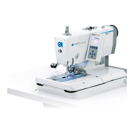
Page 17: Machine Description
Machine description Machine description Machine Fig. 1: Machine Description (1) ① ③ ② (1) - Button for threading mode (3) - Control panel (2) - Buttons Operating Instructions 581 - 01.0 - 05/2016... -
Page 18: Control Panel
The OP5000 control panel is located on the side of the machine and is connected to the control. Using the control panel, you can set the functions for the relevant buttonhole. The control panel comprises: • Display • Buttons Operating Instructions 581 - 01.0 - 05/2016... - Page 19 • Moves one level down • Changes to previous buttonhole shape ④ • Moves to the menu item one field lower • Reduces values ⑤ • Calls up values • Saves changed values Operating Instructions 581 - 01.0 - 05/2016...
- Page 20 • Changes to the next buttonhole shape ⑦ • Moves to the menu item one field higher • Increases values ⑧ • Calls up service mode ⑨ • Calls up the setting mode for buttonhole sequences Operating Instructions 581 - 01.0 - 05/2016...
-
Page 21: Operation
Complete the following steps in preparation of sewing before starting to work: • Inserting/changing the needle • Threading the needle thread • Inserting and winding on the looper thread • Adjusting the thread tension Operating Instructions 581 - 01.0 - 05/2016... -
Page 22: Switching On And Off The Machine
YYYY-MM-DD stands for the current date: Fig. 4: Switching on the power supply The machine moves to the loading position and is ready to sew, when the main menu ( p. 47) appears. Operating Instructions 581 - 01.0 - 05/2016... - Page 23 Turn the main switch (1) into position 0. All drives and the control are disconnected from the mains grid. The following appears on the display: Fig. 5: Switching off the power supply Operating Instructions 581 - 01.0 - 05/2016...
-
Page 24: Activating And Deactivating Threading Mode
The sewing drive is separated from the power supply. The slitting blade is switched off. You can now: • insert the needle • thread the looper thread • thread the needle thread • thread the gimp thread Operating Instructions 581 - 01.0 - 05/2016... -
Page 25: Inserting/Changing The Needle
Fig. 7: Inserting/changing the needle (1) ② ① (1) - Screw (2) - Needle To insert or change the needle: Loosen the screw (1). Pull the needle (2) from the needle bar. Operating Instructions 581 - 01.0 - 05/2016... - Page 26 Align the needle (2) such that the groove is facing forwards and the flat part (only in needle system 579) on the needle piston (3) is facing to the left in the direction of the screw (1). Tighten the screw (1). Operating Instructions 581 - 01.0 - 05/2016...
-
Page 27: Threading The Needle Thread
Thread the needle thread when the machine is switched off or in threading mode. To thread the needle thread: Thread the needle thread as shown in the figures. Fig. 9: Threading the needle thread (1) ① (1) - Thread guide Operating Instructions 581 - 01.0 - 05/2016... - Page 28 Pull the needle thread down with the threading wire. Guide the needle thread to the left behind the tension disk (5) and thread it into the needle from the back to the front. Operating Instructions 581 - 01.0 - 05/2016...
-
Page 29: Threading The Looper Thread
Step Remove the clamping plates ( p. 37). Swivel the machine up ( p. 39). Thread the looper thread (1) using the long threading wire (accessory pack) as shown in the figures. Operating Instructions 581 - 01.0 - 05/2016... - Page 30 Operation Fig. 13: Threading the looper thread (1) ① (1) - Looper thread Fig. 14: Threading the looper thread (2) ① (1) - Looper thread Operating Instructions 581 - 01.0 - 05/2016...
- Page 31 Fig. 15: Threading the looper thread (3) ① (1) - Looper thread Leave an end of looper thread approx. 25 mm long hanging out from the hole in the throat plate. Fit the clamping plates. Operating Instructions 581 - 01.0 - 05/2016...
-
Page 32: Threading The Gimp Thread
Thread the gimp thread (1) as shown in the figures. Threading the gimp thread: Subclass 112, 312 and 151 Fig. 16: Threading the gimp thread: Subclass 112, 312 and 151 (1) ① (1) - Gimp thread Operating Instructions 581 - 01.0 - 05/2016... - Page 33 Leave an end of gimp thread approx. 25 mm long hanging out from the gimp hole in the throat plate. Fig. 18: Threading the gimp thread: Subclass 112, 312 and 151 (3) ① (1) - Gimp thread Operating Instructions 581 - 01.0 - 05/2016...
- Page 34 Fig. 20: Threading the gimp thread: Subclass 141 and 341 (2) Sew the buttonhole and check whether the gimp is pulled back far enough. If necessary, rethread the gimp thread as shown in B. Operating Instructions 581 - 01.0 - 05/2016...
- Page 35 Fig. 21: Threading the gimp thread: Subclass 141 and 341 (3) Threading the gimp thread: Subclass 121 and 321 Fig. 22: Threading the gimp thread: Subclass 121 and 321 (1) ① (1) - Gimp thread Operating Instructions 581 - 01.0 - 05/2016...
-
Page 36: Thread Tension
Regulate the residual tension (cutting tension) to suit the elasticity of the needle thread used, so that the thread end hanging from the needle is sufficiently long to ensure a safe sewing start. Operating Instructions 581 - 01.0 - 05/2016... -
Page 37: Setting The Looper Thread Tension
• Increase the looper thread tension: turn clockwise • Reduce the looper thread tension: turn counterclockwise Swivel down the machine head. The length of the starting thread can be adjusted by changing the thread tension at the start. Operating Instructions 581 - 01.0 - 05/2016... -
Page 38: Using Threads And Gimp Threads
The purpose of gimp is to stabilize the buttonhole and at the same time make it flexible. It should have the following characteristics: • not too thick, but supple and firm • even thickness Operating Instructions 581 - 01.0 - 05/2016... -
Page 39: Removing And Fitting Clamping Plates
Remove the clamping plate (2) sideways to the right. Slightly raise the left clamping plate (1) at the back and pull it backwards. Remove the clamping plate (1) sideways to the left. Operating Instructions 581 - 01.0 - 05/2016... - Page 40 Fig. 26: Fitting clamping plates ③ (3) - Pin To fit the clamping plates: Push the clamping plate forward into the mounting. Allow the clamping plate to engage at the back into the pin (3). Operating Instructions 581 - 01.0 - 05/2016...
-
Page 41: Swiveling The Machine Up And Down
Release the locking bolt (1) again and allow it to engage in a hole. To do this, you may have to swivel the machine up and down a little. Do not let go of the machine until the locking bolt (1) has engaged. Operating Instructions 581 - 01.0 - 05/2016... - Page 42 Hold the machine firmly when swiveling it down. NOTICE Property damage may occur! Operating the machine when it is swiveled up can result in property damage. Always swivel the machine down before starting to sew. Operating Instructions 581 - 01.0 - 05/2016...
-
Page 43: Changing The Blade
Insert the new blade (4) to the base of the groove and bend in the direction of the arrow. Re-tighten the screws (1). Tighten the bobbin case retainer using the screw (1). Important The blade may not project outside the bobbin case retainer! Operating Instructions 581 - 01.0 - 05/2016... -
Page 44: Sewing
• Button 1: Clamps are opened / closed. • Button 2: If the clamps are not lowered, they are lowered now. The sewing process starts. The buttons facilitate quick switch-off during sewing. Operating Instructions 581 - 01.0 - 05/2016... -
Page 45: Sewing With The Pedal
When the sewing process is running, you can release the pedal. The pedal supports quick switch-off during sewing. You cannot continue the sewing process with the pedal. Activating quick switch-off To activate quick switch-off: Press the pedal. The sewing process stops. Operating Instructions 581 - 01.0 - 05/2016... - Page 46 You can also use the buttons the machine for quick switch-off ( p. 42). Removing the completed sewing material for subclass 151 Fig. 30: Removing the completed sewing material for subclass 151 ② ① (1) - Blade (2) - Thread clamp Operating Instructions 581 - 01.0 - 05/2016...
- Page 47 To remove the finished sewing material: Guide the looper thread and the gimp thread under the thread clamp (2). Pull both threads from right to left along the blade (1). The threads are cut. Operating Instructions 581 - 01.0 - 05/2016...
- Page 48 Operation Operating Instructions 581 - 01.0 - 05/2016...
-
Page 49: Programming
② ⑥ ⑤ ③ ④ (1) - Sequential number (4) - Piece counter (2) - Buttonhole sequence (5) - Cutting mode (3) - Buttonhole shape (6) - Cutting length (7) - Thread tension Operating Instructions 581 - 01.0 - 05/2016... - Page 50 2 blade positions are possible. Active monoflex mode is indicated by display of a bar next to the buttonhole shape: Fig. 33: Monoflex mode ⑨ ⑩ (9) - Blade position 1 (10) - Blade position 2 Operating Instructions 581 - 01.0 - 05/2016...
-
Page 51: Structure
Fig. 34: Display for automatic operation After sewing a buttonhole, the control changes automatically to the next buttonhole shape. After sewing the last buttonhole, the control changes back to the first buttonhole shape within the sequence. Operating Instructions 581 - 01.0 - 05/2016... - Page 52 Precisely 2 programs must be entered in the sequence. Light barrier mode can be recognized by the symbol (1). Fig. 36: Light barrier mode ① (1) - Symbol Operating Instructions 581 - 01.0 - 05/2016...
-
Page 53: User Level
Fig. 37: Single buttonhole mode ① ③ ② (1) - Buttonhole shape (2) - Values (3) - Buttonhole number To select a pre-programmed buttonhole: Using the button, navigate to the field Buttonhole number (3). Operating Instructions 581 - 01.0 - 05/2016... -
Page 54: Sequential Mode
There are 2 steps for selecting a buttonhole in sequential mode: Order Select a sequential number. Select a buttonhole. Fig. 38: Sequential mode ① ④ ③ ② (1) - Buttonhole shape (3) - Sequence (2) - Values (4) - Sequential number Operating Instructions 581 - 01.0 - 05/2016... - Page 55 Sequence (3). Press the button. Use the button to change the operating mode. The arrows between the buttonhole shapes appear or disappear as appropriate. Confirm the selection with the button. Operating Instructions 581 - 01.0 - 05/2016...
-
Page 56: Setting The Cutting Length
To set the cutting length: Use the button to navigate to the field Cutting length (1). Press the button. The cursor flashes. Use the buttons to set the desired value. Confirm with the button. Operating Instructions 581 - 01.0 - 05/2016... -
Page 57: Setting The Thread Tension
To set the thread tension: Use the button to navigate to the field Thread tension (1). Press the button. The cursor flashes. Use the buttons to set the desired value. Confirm with the button. Operating Instructions 581 - 01.0 - 05/2016... -
Page 58: Setting The Cutting Mode
Fig. 41: Setting cutting mode in sequential mode ① (1) - Cutting mode To set the cutting mode: Use the button to navigate to the field Cutting mode (1). Press the button. The cursor flashes. Operating Instructions 581 - 01.0 - 05/2016... -
Page 59: Resetting The Piece Counter
The menu bar changes. Hold the button for approx. 2 seconds. The piece counter is set to 0 and the display changes back to the main menu ( p. 51). Operating Instructions 581 - 01.0 - 05/2016... -
Page 60: Buttonhole Programming
( p. 51). Press the button. Select the desired buttonhole number using the buttons Press the button. Using the buttons select the bartack form Press the button. Select the desired bartack using the buttons Operating Instructions 581 - 01.0 - 05/2016... - Page 61 Using the button you can move one level higher and set further values (see the following list of menu items and sub-menu items). Or, you can quit the setting mode using the button. Operating Instructions 581 - 01.0 - 05/2016...
- Page 62 Thread cutting length: The length of the needle thread and of the looper thread end can be changed on the 581-112 or 581-312 on the buttonhole underside. Condensing stitches increase the seam safety at seam beginning and seam end.
- Page 63 Multiflex mode cutting range: 1 = Total cut, 2 = Middle cut, 3 = Eye cut or edge cut/bar cut Cutting length for total cut: The cutting length can be shorted by max. 2 mm. Operating Instructions 581 - 01.0 - 05/2016...
- Page 64 - from 31 mm buttonhole length 4 stages In this menu item, you can increase or reduce the preset cutting force, depending on the buttonhole length. Flexible cutting: Monoflex mode 581-312 or 581-321 or 581-341 Taper bar settings Taper bar length: The taper bar length can be adjusted, depending on the sewing direction and buttonhole length, from 2 mm to max.
- Page 65 (100 %) to the eye (0 %). Overlap in the round tack: Overlap of seam beginning and seam end in the round tack. Operating Instructions 581 - 01.0 - 05/2016...
-
Page 66: Sequence Programming
Programming Value Description Gimp monitoring (only for additional equipment 581-141 and 581-341): Monitoring on/off, as to whether the gimp thread is inserted. Following buttonhole: Number of the buttonhole that is sewn directly after this buttonhole without opening the clamps. This makes it possible to carry out double passes. - Page 67 (1) - Position within the sequence (3) - Number of buttonholes (2) - Buttonhole number Select the desired sequential number using the buttons Press the button. The following appears on the display: Operating Instructions 581 - 01.0 - 05/2016...
- Page 68 10. Use the buttons to set the desired number of but- tonholes (3 column of the display). 11. Confirm with the button. You can add further buttonhole programs. Start again with step 1. Operating Instructions 581 - 01.0 - 05/2016...
-
Page 69: Deleting A Buttonhole At The End Of A Sequence
Press the button. Select the desired buttonhole program using the buttons Press the button. When you want to quit setting mode, press the button. This will take you back to the user level. Operating Instructions 581 - 01.0 - 05/2016... -
Page 70: Inserting A Buttonhole Within A Sequence
0. Press the button. The sequential mode is switched off. Press the button. The setting mode is ended. This will take you back to the user level. Operating Instructions 581 - 01.0 - 05/2016... -
Page 71: Service Mode
The input mask for the code appears on the display. Using the arrow buttons enter the code 2548. Press the button. The service menu appears on the display: Operating Instructions 581 - 01.0 - 05/2016... - Page 72 You can select the individual menus using the arrow buttons. The selected menu is activated by pressing the button. To exit service mode: Press the button. The control switches back to the main menu. Operating Instructions 581 - 01.0 - 05/2016...
-
Page 73: Buttonhole Cycle
• 2: Sewing time (measured from the time sewing starts to the time sewing ends) Changes to the parameters have an effect on cycle time and sewing time. Operating Instructions 581 - 01.0 - 05/2016... -
Page 74: Menu Structure
p. 80 Cut. time p. 81 E-group 1.5.1 Subclass 1.5.2 Equipment p. 84 Threading pos. 1.6.1 Standard 1.6.2 Parallel p. 85 Operation mode 1.7.1 Standard 1.7.2 Sample 1.7.3 Tandem 1.7.4 Indexer Operating Instructions 581 - 01.0 - 05/2016... - Page 75 User config. Used to change p. 92 Language language, and technical 2.1.1 Deutsch settings 2.1.2 English 2.1.3 Numbers p. 94 Start Mode p. 96 Sew.lamp p. 97 Key tones Operating Instructions 581 - 01.0 - 05/2016...
- Page 76 3.3.1 Import 3.3.2 Export p. 113 Events 3.4.1 All events 3.4.2 Latest events Data transfer Load/save files p. 116 Import p. 117 Export p. 119 Reset data Reset data Operating Instructions 581 - 01.0 - 05/2016...
-
Page 77: Menu Item Machine Config
Load. pos. Loading 0-68 position: Distance from the cutting point To set the loading position: Select ( p. 69) Machine config in service mode. Press the button. The following appears on the display: Operating Instructions 581 - 01.0 - 05/2016... - Page 78 Programming Fig. 47: Load. pos. Press the button. 68 appears on the display. The preset value is identical to the seam start position. Enter the desired value using the arrow buttons. Operating Instructions 581 - 01.0 - 05/2016...
-
Page 79: Zigzag Stitch Width
To check the zigzag stitch width: Select ( p. 69) Machine config in service mode. Press the button. Press the button as often as required until ZZ range is highlighted on the display. Operating Instructions 581 - 01.0 - 05/2016... - Page 80 Programming Fig. 48: ZZ range Under ZZ range the set value (here: 2) is displayed. You can only adjust the zigzag stitch width using the corresponding sewing equipment ( p. 81). Operating Instructions 581 - 01.0 - 05/2016...
-
Page 81: Thread Mon
To set the remaining thread monitor: Select ( p. 69) Machine config in service mode. Press the button Press the button as often as required until Thread mon. is highlighted on the display. Fig. 49: Thread mon. Operating Instructions 581 - 01.0 - 05/2016... -
Page 82: Cut. Time
To set the switch-on time of the cutting block: Select ( p. 69) Machine config in service mode. Press the button. Press the button as often as required until Cut. time is highlighted on the display. Operating Instructions 581 - 01.0 - 05/2016... -
Page 83: E-Group
To set the sewing equipment: Select ( p. 69) Machine config in service mode. Press the button. Press the button as often as required until E-group is highlighted on the display. Operating Instructions 581 - 01.0 - 05/2016... - Page 84 Programming Fig. 51: E-group (1) Press the button. The following appears on the display: Fig. 52: E-group (2) Press the button to select Equipment. Press the button. Enter the selected sewing equipment. Operating Instructions 581 - 01.0 - 05/2016...
- Page 85 E1504 E1524 E1551 E1571 E1553 E1573 E1590 E1595 E3101 E3121 E3201 E3221 E3401 E3421 Information For subclasses 141 and 314 it is also possible to set acquired length packages in the E-group subitem. Operating Instructions 581 - 01.0 - 05/2016...
-
Page 86: Threading Position
Select ( p. 69) Machine config in service mode. Press the button. Press the button as often as required until Threading position is highlighted on the display. Fig. 53: Threading position Press the button. Standard appears on the display. Operating Instructions 581 - 01.0 - 05/2016... -
Page 87: Operation Mode
You can check buttonholes in sample mode. To set the operating mode: Select ( p. 69) Machine config in service mode. Press the button. Press the button as often as required until Operation mode is highlighted on the display. Operating Instructions 581 - 01.0 - 05/2016... -
Page 88: Tension Data
The corresponding values will be enclosed with the magnet in a new order. To set the tension data: Select ( p. 69) Machine config in service mode. Press the button. The following appears on the display: Operating Instructions 581 - 01.0 - 05/2016... - Page 89 Value 1 is highlighted on the display. If you want to change the highlighted characteristic value, press button. If you want to change a different characteristic value, press the button as often as required until that value is highlighted. Operating Instructions 581 - 01.0 - 05/2016...
-
Page 90: Multiflex (581-321 And 581-341 Only)
• Blade number for right blade To set the cutting system: Select ( p. 69) Machine config in service mode. Press the button. Press the button as often as required until Multiflex is highlighted on the display. Operating Instructions 581 - 01.0 - 05/2016... - Page 91 Programming Fig. 56: Multiflex Press the button. Mono appears on the display. Press the button. Multi appears on the display. Press the button. Operating Instructions 581 - 01.0 - 05/2016...
-
Page 92: Zz Offset
The subitem ZZ offset is used to set the compensation for the zigzag stitch offset. Parameters in the ZZ offset subitem Possible Icon Entry Meaning Preset value value range ZZ offset Zigzag stitch 0.8-1.6 offset Operating Instructions 581 - 01.0 - 05/2016... -
Page 93: Cut Control
• Only open clamps in the loading position (1) • Subsequent sewing pattern (2) • Extended min or max limits (4) • Open clamps together (8) • Extra-long buttonholes (16) Up to 31 combinations are possible here. Operating Instructions 581 - 01.0 - 05/2016... -
Page 94: Menu Item User Config
• Deutsch guage for the • English user interface • Numerical To select the language: Select ( p. 69) User config. in service mode. Press the button. The following appears on the display: Operating Instructions 581 - 01.0 - 05/2016... - Page 95 Fig. 57: Language (1) Press the button. The following appears on the display: Fig. 58: Language (2) Press the button as often as required until the desired language is highlighted. Press the button. Operating Instructions 581 - 01.0 - 05/2016...
-
Page 96: Buttons
To convert the way in which the buttons function: Select ( p. 69) User config. in service mode. Press the button. The following appears on the display: Operating Instructions 581 - 01.0 - 05/2016... - Page 97 Press the button so that Buttons is highlighted on the display. Press the button. 2 appears on the display. 10. Press the button. 1 appears on the display. 11. Press the button. Operating Instructions 581 - 01.0 - 05/2016...
-
Page 98: Sew.lamp
The following appears on the display: Fig. 60: Sew.lamp Press the button as often as required until Sew.lamp is highlighted on the display. Press the button. 100 appears on the display. Operating Instructions 581 - 01.0 - 05/2016... -
Page 99: Key Tones
Press the button as often as required until Key tones is highlighted on the display. Press the button. 0 appears on the display. Set the desired peep duration using the arrow buttons. Operating Instructions 581 - 01.0 - 05/2016... -
Page 100: Menu Item Test Functions
Additional measuring equipment is not required. To select the Multitest subitem: Select ( p. 69) Test functions in service mode. Press the button. The following appears on the display: Operating Instructions 581 - 01.0 - 05/2016... - Page 101 Testing an output element can lead to collisions with other machine elements. There is a risk of breaking Before switching on each output element, make sure that this cannot collide with other components. Operating Instructions 581 - 01.0 - 05/2016...
- Page 102 Press the button. The output is switched over. Functions of the operating elements Output Function Needle thread cutter; for 581-112 and 581-312 additional looper thread cutter Looper thread tension Fabric clamp Spreader Needle thread advancing device Slitter Slitter Looper thread advancing device;...
- Page 103 Programming Output Function Looper thread cutter; only on the 581-121, 581-141 and 581-321, 521-341 Multiflex blade Multiflex cutting block Slitter You can quit the output test using the button. Input test In the subitem Input test you can test the individual input elements.
- Page 104 To perform the automatic input test: Select Auto input tst. Press the button. When the status of an input is changed, this input is automati- cally displayed. You can quit the automatic input test using the button. Operating Instructions 581 - 01.0 - 05/2016...
- Page 105 To carry out the sewing motor test: Select Sew. motor tst. Press the button. Use the button to increase the speed. Use the button to reduce the speed. Quit the motor test using the button. Operating Instructions 581 - 01.0 - 05/2016...
- Page 106 X = X-direction (transverse movement of the fabric support plate) Y = Y-direction (longitudinal movement of the fabric support plate) Z = Z-direction (rotation of the sewing mechanism) Quit the stepper motor test using the button. Operating Instructions 581 - 01.0 - 05/2016...
- Page 107 When the RAM test is ended, one of two events is displayed: • OK = Working memory is working properly • Error = Error in the working memory Quit the RAM test using the button. Operating Instructions 581 - 01.0 - 05/2016...
-
Page 108: Sewing Proc
Select ( p. 69) Test functions in service mode. Press the button. The following appears on the display: Fig. 62: Sewing proc. Press the button so that Sewing proc. is highlighted on the display. Operating Instructions 581 - 01.0 - 05/2016... - Page 109 • 2 = After switching the valves for the relevant thread cutting system, the sewing process is stopped. • 3 = After switching each valve, the sewing process is stopped. You can quit the test program by pressing and then Operating Instructions 581 - 01.0 - 05/2016...
- Page 110 In the subitem St.cont.operat you can start a continuous run. Before the start of sewing, a security prompt is first displayed, which must be confirmed with Yes. To start a continuous run: Select St.cont.operat. Press the button. Operating Instructions 581 - 01.0 - 05/2016...
- Page 111 To check the sewing tools: Select Looper adjust. Press the button. The machine performs a reference run. The following appears on the display: Fig. 63: Looper adjust. (1) Operating Instructions 581 - 01.0 - 05/2016...
- Page 112 In this position, the needle bar must be at top dead center. Press the button. The following appears on the display: Fig. 65: Looper adjust. (3) Operating Instructions 581 - 01.0 - 05/2016...
- Page 113 The screws for the looper setting are now accessible. Change the looper setting. Swivel the machine down. Press the button. The sewing motor moves back into the test position 2 again. Check the looper setting. Operating Instructions 581 - 01.0 - 05/2016...
- Page 114 (see following table). Important When setting the needle bar height, you need to choose the position such that the entire needle eye can be seen below the left looper tip! Operating Instructions 581 - 01.0 - 05/2016...
-
Page 115: Events
The following options are available: • All events • Latest events All events In the subitem All events all events that have occurred are displayed. An explanation of the error messages is provided on p. 159. Operating Instructions 581 - 01.0 - 05/2016... - Page 116 You can quit the subitem using the button. Latest events In the subitem Latest events the events that occurred most recently are displayed. An explanation of the error messages is provided on p. 159. Operating Instructions 581 - 01.0 - 05/2016...
- Page 117 Programming Example: Fig. 69: Latest events To call up the latest events: Select Latest events. Press the button. The latest events are displayed. You can quit the subitem using the button. Operating Instructions 581 - 01.0 - 05/2016...
-
Page 118: Menu Item Data Transfer
The data is imported. If the buttonhole programs originate from a machine with a different subclass or from a different item of sewing equipment, the follow- ing information appears on the display: Operating Instructions 581 - 01.0 - 05/2016... -
Page 119: Export
The menu item Export allows you to save buttonhole programs from the machine to a USB key. To select the Export subitem: Select ( p. 69) Data transfer in service mode. Press the button. The following appears on the display: Operating Instructions 581 - 01.0 - 05/2016... - Page 120 The following appears on the display: Fig. 73: Export (1) Press the button to save the data to the USB key. The data is exported, and the display returns to Import/ Export. Operating Instructions 581 - 01.0 - 05/2016...
-
Page 121: Menu Item Reset Data
For security reasons, you are asked to input the code once again. Only the calibration values and the set subclass are retained. Operating Instructions 581 - 01.0 - 05/2016... - Page 122 Programming Operating Instructions 581 - 01.0 - 05/2016...
-
Page 123: Maintenance
Remove accumulations of fluff Remove any lint in the area below the throat plate Check the oil level Check and clean the toothed belt Lubricate the cutting punch Operating Instructions 581 - 01.0 - 05/2016... - Page 124 Lubricate the felt at the cam plate Pneumatic system Check the water level in the pressure controller Clean the filter element in the compressed air maintenance unit Check the tightness of the system Operating Instructions 581 - 01.0 - 05/2016...
-
Page 125: Cleaning
If a vacuum is available, it is recommended to vacuum the sewing waste. If required, empty the cutting waste from the suction container. Operating Instructions 581 - 01.0 - 05/2016... -
Page 126: Lubricating
For topping off the oil reservoir, use only lubricating oil DA 10 or oil of equivalent quality with the following specifications: • Viscosity at 40 °C:10 mm • Flash point: 150 °C Operating Instructions 581 - 01.0 - 05/2016... - Page 127 Container Part no. 250 ml 9047 000011 9047 000012 9047 000013 9047 000014 Fig. 74: Lubricating (1) ① (1) - Cutting punch Lubricate the machine as follows: Lubricate the cutting punch (1). Operating Instructions 581 - 01.0 - 05/2016...
- Page 128 (2) - Cam disk Lubricate the felt at the cam plate (2). Fig. 76: Lubricating (3) ④ ③ (3) - Felt (4) - Clamping arm Lubricate the felts (3) of the clamping arms (4). Operating Instructions 581 - 01.0 - 05/2016...
-
Page 129: Servicing The Pneumatic System
Water condensation accumulates in the water separator (2) of the pressure controller. Proper setting Water condensation must not rise up to the level of the filter element (1). Check the water level in the water separator (2) on a daily basis. Operating Instructions 581 - 01.0 - 05/2016... - Page 130 Place the collection tray under the drain screw (3). Loosen the drain screw (3) completely. Allow water to drain into the collection tray. Tighten the drain screw (3). Connect the machine to the compressed air supply. Operating Instructions 581 - 01.0 - 05/2016...
-
Page 131: Cleaning The Filter Element
Blow out the filter element (1) using a compressed air gun. Wash out the filter tray using benzine. Tighten the filter element (1). Tighten the water separator (2). Tighten the drain screw (3). 10. Connect the machine to the compressed air supply. Operating Instructions 581 - 01.0 - 05/2016... -
Page 132: Changing The Cutting Blocks And Blade
Fig. 79: Changing the cutting block ① ② (1) - Screw (2) - Cutting block To replace the cutting block: Loosen the screw (1) (Allen key in the accessory pack). Pull the cutting block (2) forward and remove. Operating Instructions 581 - 01.0 - 05/2016... - Page 133 (3) - Blade (4) - Screw To change the blade: Loosen the screw (4). Pull the blade (3) forward and remove. Insert the new blade and push to the end stop. Re-tighten the screw (4). Operating Instructions 581 - 01.0 - 05/2016...
-
Page 134: Subclass With Multiflex
Push the new cutting block (2) into the guide and tighten the screw (3). Reconnect the compressed air hose. When the compressed air is connected ( p. 146), the cutting block holder automatically moves back up. Operating Instructions 581 - 01.0 - 05/2016... - Page 135 Loosen screw (5) or (6) (Allen key in the accessory pack). Remove blade (4) or (7). Insert the new blade and tighten with screw (5) or (6). Important If you cannot remove the blade, slightly loosen the screw of the second blade. Operating Instructions 581 - 01.0 - 05/2016...
-
Page 136: Parts List
If you want to use a blade with a different shape, you must make the appropriate settings on the control panel ( Service Instructions). Parts list A parts list can be ordered from Dürkopp Adler. Or visit our website for further information at: www.duerkopp-adler.com Operating Instructions 581 - 01.0 - 05/2016... -
Page 137: Setup
Removing the transport locks All transport locks must be removed prior to setup. To remove the transport locks: Remove the lashing straps and wooden blocks from the • Machine head • Machine table • Stand Operating Instructions 581 - 01.0 - 05/2016... - Page 138 The screw prevents the machine head from swiveling up during transport. Fig. 84: Removing the transport lock of the clamping plates ② ② (2) - Screws Remove screws (2). The screws prevent the clamping plates from falling out. Operating Instructions 581 - 01.0 - 05/2016...
-
Page 139: Assembling The Stand
• Assemble the compressed air maintenance unit ( p. 147) Assembling the tabletop If you want to make your own tabletop, use the drawing ( p. 185) as a template for the dimensions. The tabletop should be approx. 40 mm thick. Operating Instructions 581 - 01.0 - 05/2016... -
Page 140: Using The Ring Bolt
2 people lift the machine. The ring bolt is in the accessory pack. To use the ring bolt: Screw the ring bolt (1) onto the machine. Lift the machine (2) into the stand. When the machine is assembled, unscrew the ring bolt (1) again. Operating Instructions 581 - 01.0 - 05/2016... -
Page 141: Assembling The Reel Stand
Align the thread reel holder (2) and thread guide (1) so that thread reel holder and thread guide are parallel to one another. Information You must set the centering piece to suit the type of thread reel. Incorrect settings can result in sewing disruptions. Operating Instructions 581 - 01.0 - 05/2016... -
Page 142: Securing The Stand
Screw both support plates (3) on the nut (2) as far down as required to ensure that the machine is firm and secure. Screw the counternut (1) upward. Tighten the counternut (1) slightly. Operating Instructions 581 - 01.0 - 05/2016... -
Page 143: Setting The Working Height
Adjust the tabletop of the machine so that it is level at the desired working height. To avoid jamming, slide the tabletop in or out evenly at both sides. Tighten the screws (1). Operating Instructions 581 - 01.0 - 05/2016... -
Page 144: Assembling The Control
To assemble the control: Use screws to mount the control to the underside of the table- top at positions (1) and (2). The side housing the type plate will be pointing to the left. Operating Instructions 581 - 01.0 - 05/2016... - Page 145 (4), and the connections (3) on the housing are labeled corre- spondingly. The cable and the connection have the same designation or the same symbol. Connect all plugs with the connections. Operating Instructions 581 - 01.0 - 05/2016...
-
Page 146: Electrical Connection
You establish the electrical connection as follows: Connect the machine in accordance with the wiring diagram ( p. 185). 7.11 Establishing equipotential bonding To establish equipotential bonding: Establish equipotential bonding in accordance with the wiring diagram ( p. 185). Operating Instructions 581 - 01.0 - 05/2016... -
Page 147: Assembling The Suction Container
Connect the hose (3) to the suction container via the injector. Cutting waste is extracted via the hose (3) into the container (4). Screw the angle piece (1) onto the injector. Connect the suction container with the pressure supply via the hose (2). Operating Instructions 581 - 01.0 - 05/2016... -
Page 148: Pneumatic Connection
Ensure that no oil particles enter the compressed air supply. NOTICE Property damage from incorrect setting! Incorrect system pressure can result in damage to the machine. Ensure that the machine is only used when the system pressure is set correctly. Operating Instructions 581 - 01.0 - 05/2016... -
Page 149: Assembling The Compressed Air Maintenance Unit
Assemble the compressed air maintenance unit (1) to the tabletop using screws (2). Fig. 94: Assembling the compressed air maintenance unit (2) ⑥ ③ ④ ⑤ (3) - Distributor (5) - Hose (4) - Valve (6) - Connection hose Operating Instructions 581 - 01.0 - 05/2016... -
Page 150: Setting The Operating Pressure
Use only DA 10 lubricant or an equivalent oil conforming to the following specifications for lubrication: • Viscosity at 40° C: 10 mm²/s • Flash point: 150° C Operating Instructions 581 - 01.0 - 05/2016... - Page 151 Unscrew the head and side covers. Fig. 95: Lubricating (1) ① ③ ② (1) - Wick (3) - Needle bar (2) - Wick Fig. 96: Lubricating (2) ④ ⑤ (4) - Wick (5) - Felt Operating Instructions 581 - 01.0 - 05/2016...
- Page 152 Topping off the oil For topping off the oil reservoir, use only lubricating oil DA 10 or oil of equivalent quality with the following specifications: • Viscosity at 40 °C:10 mm • Flash point: 150 °C Operating Instructions 581 - 01.0 - 05/2016...
- Page 153 Fig. 98: Topping off the oil (1) ① ② (1) - Fill opening (2) - Oil reservoir To top off with oil: Top off the oil reservoir (2) through the fill openings (1) up to the MAX mark Operating Instructions 581 - 01.0 - 05/2016...
- Page 154 Fig. 99: Topping off the oil (2) ③ ④ (3) - Fill opening (4) - Oil reservoir Top off the oil reservoir (4) through the fill opening (3) up to the MAX mark. Operating Instructions 581 - 01.0 - 05/2016...
-
Page 155: Adjusting The Material Edge Stops
(2) on the right and left sides. Loosen the screws (1) on the right and left sides. Set the sewing position by moving the material edge stops (2) back and forth. Re-tighten the screws (1). Operating Instructions 581 - 01.0 - 05/2016... -
Page 156: Carrying Out A Test Run
If the welcome screen does not appear on the control panel after switching on even after waiting for a long time, this means that there is no software on the control. In this case, the software must first be installed ( Service Instructions). Operating Instructions 581 - 01.0 - 05/2016... -
Page 157: Decommissioning
Cover the control panel to protect it from soiling. Cover the control to protect it from soiling. Cover the entire machine if possible to protect it from soiling and damage. Operating Instructions 581 - 01.0 - 05/2016... - Page 158 Decommissioning Operating Instructions 581 - 01.0 - 05/2016...
-
Page 159: Disposal
When disposing of the machine, be aware that it consists of a range of different materials (steel, plastic, electronic components, …). Follow the applicable national regulations when disposing of these materials. Operating Instructions 581 - 01.0 - 05/2016... - Page 160 Disposal Operating Instructions 581 - 01.0 - 05/2016...
-
Page 161: Troubleshooting
The thread breaks during • Press the button on the sewing head cover to move to the threading position Operating Instructions 581 - 01.0 - 05/2016... - Page 162 2, or gimp monitoring) stopped with the ESC button or button 1 The serial number of the • Press the OK button machine has not been • Contact DA service entered Operating Instructions 581 - 01.0 - 05/2016...
- Page 163 • Continue with YES: Caution! the update will overwrite all existing data Continue with NO: Abort • Order and load the correct software Machine ID has not been • Press the OK button initialized Operating Instructions 581 - 01.0 - 05/2016...
-
Page 164: Error Messages
• Sewing motor blocked • Remove the blockage feed fault • Encoder cable not • Check the encoder cable connected or defective and replace, if necessary • Encoder defective • Replace the sewing motor Operating Instructions 581 - 01.0 - 05/2016... - Page 165 (9815 935006) 1052 Sewing motor • Sewing motor cable • Replace the sewing motor overcurrent defective cable • Sewing motor defective • Replace the sewing motor • Control defective • Replace the control Operating Instructions 581 - 01.0 - 05/2016...
- Page 166 • Encoder defective • Replace the sewing motor 1330 Sewing motor not • Switch the machine off and responding on again • Perform software update • Contact Customer Service Operating Instructions 581 - 01.0 - 05/2016...
- Page 167 • Switch the machine off and Positioning speed is defective on again not achieved • Sewing motor defective • Replace the encoder • Control defective • Replace the sewing motor • Contact Customer Service Operating Instructions 581 - 01.0 - 05/2016...
- Page 168 ..21 • Encoder plug (Sub-D, 9-pin) • Check the connection of the not connected or defective encoder cable and replace, if • Encoder defective necessary Operating Instructions 581 - 01.0 - 05/2016...
- Page 169 • Check line voltage and – interruption stabilize, if required 3103 3221 Machine: Thread • Internal error • Switch the machine off and – tension regulation on again 3222 • Perform software update • Contact Customer Service Operating Instructions 581 - 01.0 - 05/2016...
- Page 170 • Switch the machine off and – on again 6299 • Perform software update • Contact Customer Service 6361 Machine ID not found • Check the plug 6365 Internal memory faulty • Control defective • Replace the control Operating Instructions 581 - 01.0 - 05/2016...
- Page 171 8151 IDMA error • Internal error • Switch the machine off and • Disturbance on again – • Control defective • Perform software update 8161 • Replace the control • Contact Customer Service Operating Instructions 581 - 01.0 - 05/2016...
- Page 172 • Reset the data ( Service Instructions) • Contact Customer Service 9009 Cutting punch is not in • Cutting position sensor • Check the plug and cable position and replace, if required • Replace the distributor board Operating Instructions 581 - 01.0 - 05/2016...
-
Page 173: Errors In Sewing Process
• Check the thread path thread tubes, thread guide or thread take-up disk are sharp-edged • Throat plate, looper or • Have parts reworked by spreader have been qualified specialists damaged by the needle Operating Instructions 581 - 01.0 - 05/2016... - Page 174 • The looper or spreader is • Check individual settings misaligned • Throat plate, looper or • Have parts reworked by spreader have been qualified specialists damaged by the needle Operating Instructions 581 - 01.0 - 05/2016...
- Page 175 • Cutting edge of blade is blunt • Replace and set blade or chipped ( Service Instructions) • A cutting block that does not • Replace cutting block and correspond to the blade is set ( Service used Instructions) Operating Instructions 581 - 01.0 - 05/2016...
- Page 176 Fabric • Fabric support plate collides • At a low speed, check the support with other parts movement of the fabric plate support plate and watch transport out for possible collisions is faulty Operating Instructions 581 - 01.0 - 05/2016...
-
Page 177: Technical Data
[bar] Length [mm] 1060 Width [mm] Height [mm] 1050 Characteristics Basic type Double chain stitch-buttonholer or chain stitch-eyelet maker with CNC step motor technology for material feeding and for rotating the sewing mechanism. Operating Instructions 581 - 01.0 - 05/2016... - Page 178 A stepper motor drives the movements for each of the axes X, Y and Z. These drives are controlled via the electronic control DAC comfort in combination with different pneumatic machine functions. Operating Instructions 581 - 01.0 - 05/2016...
- Page 179 • Integrated Multitest testing and monitoring system. In addition to monitoring the sewing process, this can be used to quickly test the input and output elements and the motor functions without additional measuring equipment Operating Instructions 581 - 01.0 - 05/2016...
- Page 180 • Electronic setting of the intermediate material width • Modern, ergonomically cost effective design within the current DA design line • Large-surface fabric support plate with large recess depth for the distance between the buttonhole and the sewing material edge Operating Instructions 581 - 01.0 - 05/2016...
- Page 181 • Electronic changing of the zigzag stitch width in the cross tack • Due to the particular design of the machine arm, it is possible to position the sewing material in the longitudinal direction when using a different fabric holding device (additional equipment) Operating Instructions 581 - 01.0 - 05/2016...
- Page 182 Technical data Operating Instructions 581 - 01.0 - 05/2016...
-
Page 183: Glossary
Serves as a threading aid. End bartack Secures the end of a seam. Thread cutter Cuts the thread at the end of a sewing process. It is located under the sewing material support. Operating Instructions 581 - 01.0 - 05/2016... - Page 184 Determines when and whether a buttonhole is to be cut during the sewing process: • CB (before the sewing process) • CA (after the sewing process) • 0 (Cutting mode off) Changes the cutting diameter. Operating Instructions 581 - 01.0 - 05/2016...
- Page 185 Maintenance unit Comprises a water separator and pressure controller. Water separator Filters the condensed water and the dirt from the compressed air. Enriches the air with a certain quantity of oil. Operating Instructions 581 - 01.0 - 05/2016...
- Page 186 Glossary Operating Instructions 581 - 01.0 - 05/2016...
-
Page 187: Appendix
Appendix 13 Appendix Fig. 101: Tabletop Operating Instructions 581 - 01.0 - 05/2016... - Page 188 Appendix Fig. 102: Wiring diagram (1) Operating Instructions 581 - 01.0 - 05/2016...
- Page 189 Appendix Fig. 103: Wiring diagram (2) Operating Instructions 581 - 01.0 - 05/2016...
- Page 190 Appendix Fig. 104: Wiring diagram (3) Operating Instructions 581 - 01.0 - 05/2016...
- Page 191 Appendix Fig. 105: Wiring diagram (4) Operating Instructions 581 - 01.0 - 05/2016...
- Page 192 Appendix Fig. 106: Wiring diagram (5) Operating Instructions 581 - 01.0 - 05/2016...
- Page 193 Appendix Fig. 107: Wiring diagram (6) Operating Instructions 581 - 01.0 - 05/2016...
- Page 194 Appendix Fig. 108: Wiring diagram (7) Operating Instructions 581 - 01.0 - 05/2016...
- Page 195 Appendix Fig. 109: Wiring diagram (8) Operating Instructions 581 - 01.0 - 05/2016...
- Page 196 Appendix Fig. 110: Wiring diagram (9) Operating Instructions 581 - 01.0 - 05/2016...
- Page 198 DÜRKOPP ADLER AG Potsdamer Straße 190 33719 Bielefeld GERMANY Phone +49 (0) 521 / 925-00 service@duerkopp-adler.com E-mail www.duerkopp-adler.com...