DURKOPP ADLER 580 Operating Instructions Manual
Hide thumbs
Also See for 580:
- Parts list (107 pages) ,
- Operating instructions manual (120 pages) ,
- Operating instructions manual (53 pages)
Table of Contents
Advertisement
Advertisement
Chapters
Table of Contents

Related Manuals for DURKOPP ADLER 580


Summary of Contents for DURKOPP ADLER 580
- Page 1 Operating Instructions...
- Page 3 Foreword This instruction manual is intended to help the user to become familiar with the machine and take advantage of its application possibilities in accordance with the recommendations. The instruction manual contains important information on how to operate the machine securely, properly and economically. Observation of the instructions eliminates danger, reduces costs for repair and down-times, and increases the reliability and life of the machine.
-
Page 4: General Safety Instructions
General safety instructions The non-observance of the following safety instructions can cause bodily injuries or damages to the machine. 1. The machine must only be commissioned in full knowledge of the instruction book and operated by persons with appropriate training. 2. -
Page 5: Table Of Contents
Needle thread and looper thread tension ....... . . 17 Changing the cutting blocks and knives Changing the cutting blocks and knives (580-312000 / 580-321000/ 580-341000) “Multiflex” . 20 6.1.1 Changing the knives . - Page 6 Index Page: 10.3 Index of the control panel keys ........26 10.4 Main level of menu system .
-
Page 7: Product Description Designated Use
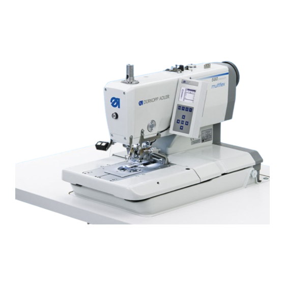
Product description Designated Use The DÜRKOPP ADLER 580 is a sewing automat designed for the sewing of buttonholes in light to medium-weight material. Such material, which is generally made of textile or synthetic fibres, is used in the clothing industry. Furthermore, this sewing automat can possibly also sew so-called technical seams. - Page 8 – The control panel with membrane keyboard that is able to display graphics is fitted on the right side of the sewing head within easy reach of the operator. – The following functions are operated via manual switches: - Closing and opening the clamp - Activating the sewing operation - Quick stop with needle position “up”...
- Page 9 Structure of product Subclasses Equipment Material number Sewing automat 0580 990001 0580 990002 0580 990025 0580 990005 0580 990021 0580 990022 0580 990026 Accessories 0791 580501 Optional equipment: Pneumatic connection set 0797 003031 Integral sewing lamp (LED) 0580 100344 Foot switch 9880 580002 Upper gimp guide 0580 590804...
- Page 10 Subclasses Equipment Material number Stands MG58-13 (regular installation) MG58 400104 Stand with fastening parts and table top 1060 x 750 incl. maintenance unit and rollers MG58-13 (regular installation of a narrow stand) MG58 400124 Stand with fastening parts and table top 620 x 750 incl.
-
Page 11: Technical Data
Rated voltage: 1 x 190-240 V, 50/60 Hz Dimensions Machine head: 550 x 370 x 580 (L x W x H) Table top (regular installation): 1060 x 750 x 1150 mm (L x W x H) Table top (narrow stand):... -
Page 12: Operation
Subclass Type and size of upper Type and size of looper Type and size of lower thread thread gimp 580-112000 Polyester fibre thread, Polyester fibre thread, not necessary schappe-silk spun schappe-silk spun 580-312000 70/3... -
Page 13: Removing And Inserting The Clamping Plates
Removing and inserting the clamping plates Caution: Danger of injury ! The removing and inserting of the clamping plates 1 has to be done with the sewing automat switched off or in the position “Threading mode” (see chapter “Threading mode”). Removing the clamping plate –... -
Page 14: Changing The Needle
Changing the needle Caution: Danger of injury ! The needle has to be changed with the sewing automat switched off or in the position “Threading mode” (see chapter “Threading mode”). – Loosen the screw 1 (Allen key in the accessories). –... - Page 15 Threading the upper thread Caution: Danger of injury ! The needle thread must only be threaded in when the machine is switched off or in the “Threading mode” (see chapter “Threading mode”). – Thread in the needle thread as shown in the illustrations. –...
-
Page 16: Threading The Looper Thread
Threading the looper thread looper thread gimp thread Caution: Danger of injury ! The looper thread must only be threaded in when the machine is switched off or in the “Threading mode” (see chapter “Threading mode”). The automat must be in its final position, i.e. the looper turret with the loopers has to point to the front. -
Page 17: Threading The Gimp Thread
Leave a gimp end approx. 25 mm long hang out of the gimp hole of the stitch plate. – Sew a buttonhole and check whether the gimp is pulled back sufficiently. With the Subclass -141000, -341000: thread in the gimp as shown in illustration B. Only for the subclass 580-141000, 580-341000... -
Page 18: Swivelling The Automat Up And Down
Swivelling the automat up and down Caution: Danger of injury ! The automat must only be swivelled up when the machine is switched off or in the “Threading mode” (see chapter “Threading mode”). For various operations (e.g. for threading the looper thread or the gimp thread) the automat has to be swivelled up. -
Page 19: Thread Tension
Thread tension Needle thread and looper thread tension The thread tensions are dependent on the type and quality of the threads and fabrics. The buttonhole looks best if it is sewn with the lowest possible thread tension. Too tight thread tensions can lead to undesired ruffling and thread breakage, particularly when processing thin materials. - Page 20 Looper thread tension – Swivel the machine head up. – Adjust the looper thread tension by means of tensioner 1. Turn the tensioner in clockwise direction in order to increase the looper thread tension. Turn the tensioner counter-clockwise in order to reduce the looper thread tension.
-
Page 21: Changing Of Cutting Blocks And Knives
Changing of cutting blocks and knives The cutting length can be altered by changing the cutting blocks. Caution: Danger of injury ! Change the cutting block or the knife only when the buttonhole automat is switched off! Change the cutting block –... -
Page 22: Changing The Cutting Blocks And Knives (580-312000 / 580-321000/ 580-341000) "Multiflex
Changing the cutting blocks and knives (580-312000 / 580-321000 / 580-341000) “Multiflex” 6.1.1 Changing the knives Caution: danger of injury Knives may only be changed with the machine switched off . – Loosen the Allen screw 2 or 4. (The Allen key is in the accessories). -
Page 23: Changing The Cutting Blocks
6.1.2 Changing the cutting blocks Caution: danger of injury The cutting-block may only be changed with the machine switched off. Removing the cutting-block – Disconnect the compressed-air supply – Use a screwdriver 2 to push gently the cutting-block holder 1 downward. -
Page 24: Push Buttons
Push buttons By means of the push buttons it is possible to control the clamps and to start the sewing operation. According to the setting in the service menu (see service instructions) the function is different. 1. Setting – Key 1: The clamps are opened or closed respectively. –... -
Page 25: Switching On - Switching Off - Threading Mode
Switching on - Switching off - Threading mode Switching on – Switch on the main switch 1. The machine moves to the loading position and is ready for sewing. Switching off – Switch off the main switch 1. All drives and the control are immediately cut off the electric supply lines. -
Page 26: General Notes
Control panel and control 10.1 General notes The buttonhole automat of the class 580 is equipped with a programmable control. Up to 50 different buttonholes can be defined. The buttonholes can be memorized in up to 25 sequences. One sequence can consist of up to 9 different buttonhole, each single buttonhole can be repeated within one sequence up to 9 times successively. -
Page 27: Control Panel
10.2 Control panel You can programme the control using the control panel and also set the fucntion of each buttonhole. This can be done through actuating directly the corresponding key or by altering some parameters. Entering the parameters should be done in the programming mode “P”. -
Page 28: Index Of The Control Panel Keys
10.3 Index of the control panel keys Key on control panel Designation of key in this manual “ESC”- key “P”- key “F”- key “S”- key “OK”- key key ï key ð key ñ key ò... -
Page 29: Main Level Of Menu System
10.4 Main level of the menu system After switching on the automat and during sewing the display shows the main level of the menu system. In the main level the following values are displayed: - Sequence number Sequence mode - Buttonhole sequence - Buttonhole number Single buttonhole mode - Empty line... - Page 30 Monoflex mode (simple cut) Two knife positions are possible with the subclasses 580-312000, 580-321000 and 580-341000 that is why the field 3 shows a bar in addition. The bar position shows which knife position is allocated to the buttonhole.
- Page 31 Confirm by pressing the “OK”-key. Monoflex mode (simple cut) Two knife positions are possible with the subclasses 580-312000, 580-321000 and 580-341000 that is why the field 3 shows a bar in addition. The bar position shows which knife position is...
-
Page 32: Selecting A Sequence Or A Buttonhole
10.4.2 Selecting a sequence or a single buttonhole Depending on the setting in the sequence menu either the sequence mode or the single buttonhole mode is available (see “Sequence programming”) 10.4.2.1 Selection of a sequence (Sequence mode) After switching on the top line of the display appears white on black. The sequence last sewn is displayed. -
Page 33: Adjusting The Thread Tension In The Main Level
10.4.3 Adjusting the thread tension in the main level The display indicates in field 2 the needle thread tension during the sewing process. The tension can be adjusted in the main level. Keys ñò Skip with the ñò keys to field 2 “needle thread tension”. -
Page 34: Cutting Mode
Confirm by pressing the “OK”-key. 10.4.6 The piece counter The buttonhole automat 580 is equipped with a piece counter that counts the number of buttonholes sewn. After the “å“ sign the current figure is indicated. The value of the piece counter is memorized also when the automat is switched off. -
Page 35: Automatic Or Manual Operation (Can Only Be Set In Sequence Mode)
10.4.7 Automatic or manual operation (only adjustable in the sequence mode) The buttonhole automat functions in manual or automatic operation mode depending on the setting. Automatic operation In the sequence indicated on the display, arrows are indicated between the types of buttonhole programs. After sewing one buttonhole the control automatically switches to the next type of buttonhole. -
Page 36: Buttonhole Programming
10.5 Buttonhole programming The menu system 580 is divided into several levels. In the main level the most important information for the sewing operation are indicated. From this main level it is possible to switch to the programming level in order to program buttonholes. -
Page 37: Programming A Buttonhole
10.5.3 Programming of a buttonhole “P”-key Press the “P”-key in order to switch from the main level to the menu for programming buttonholes. Keys ñò Select with the ñò keys the menu item “buttonhole number.” “OK”-key Press the “OK”-key to activate the menu item. Keys ñò... -
Page 38: List Of Menu And Submenu Items
Eyelet overlap*: the overlapping of the seam beginning and the seam end. Thread trimming length: with the Subclass 580-112000 / 0580-312000, it is possible to alter the length of the needle thread on the underside of the buttonhole . - Page 39 CB = cutting before sewing Cutting area: the inner distance between the lips of the buttonhole is called cutting area. Modus Multiflex 580-312000 / 580-321000 / 580-341000 Cutting area: 1 = complete cut, 2 = medium cut, 3 = eye cut or edge cut.
- Page 40 Menu item Description Flexible cutting: Monoflex mode 580-312000 / 580-321000 / 580-341000 Taper tack settings Taper tack length: the taper tack length can be set from 2 mm to 36 mm, depending on the sewing equipment and the buttonhole length.
-
Page 41: Sequences
10.6 Sequences 10.6.1 General notes Sequence mode The operator (seamstress) will be able to sew several buttonholes with different parameters successively without having to touch a key on the control panel. · Each sequence can contain up to 9 different buttonholes. Each different buttonhole within a sequence can be sewn repeatedly up to 9 times. -
Page 42: Programming A Sequence
10.6.3 Programming of a sequence “S”-key Press the ”S”-key to switch from the main level to the menu for programming a buttonhole sequence. Selection of the sequence number keys ñò Select the menu item “sequence number” with the ñò keys. “OK”-key Press the “OK”-key to activate the menu item. - Page 43 10.6.4 Adding a buttonhole at the end of a sequence keys ñò Select the last line in the programmed buttonhole sequence with the ñò keys. “OK”-key Press the “OK”-key. keys ñò Select the desired buttonhole program with the ñò keys. “OK”-key Press the “OK”-key.
- Page 44 10.6.6 Adding a buttonhole within a sequence Important note A single adding of a buttonhole program into a buttonhole sequence is not possible. Note down the programmed buttonholes that are following. Keys ñò Select the desired line of the programmed buttonhole sequence with the ñò...
-
Page 45: Sewing
10.7 Sewing The sewing operation can be controlled either with the manual switches or with the pedal. Sewing with the manual switches With the manual switch the clamps can be controlled and the sewing operation started. According to the setting in the service menu (see service instructions) the function is different. - Page 46 Removing the finished workpiece with the subclass 580-151000 – In order to remove the finished workpiece pull the looper thread and the gimp under the thread clamp 2. Pull both threads from the right to the left along the blade 1.
-
Page 47: Information Messages
Information messages 11.1 Needle not in basic position If the needle is not in its basic upper position at the sewing start, this information code will appear. Error Correction – Turn the handwheel until the information disappears. 11.2 Threading mode As long as the sewing automat is in the “Threading mode”, the information code in the margin appears. -
Page 48: Invalid Cutting Configuration
11.6 Invalid cutting configuration Hint Appears only with the “Multiflex” setting In case an invalid cutting configuration is chosen, the opposite hint appears. Error correction – Check and set the control unit and the data of the knives and cutting blocks in use. –... -
Page 49: Maintenance
Maintenance Caution: Danger of injury ! Carry out maintenance work only when the machine is switched off. Whenever maintenance work has to be done with the machine running practice utmost caution. 13.1 Cleaning A clean sewing automat helps to avoid disturbances ! Daily cleaning: –... -
Page 50: Lubricating
13.2 Lubricating Check the oil level in the oil reservoirs 4 and 5 weekly ! Caution: Danger of injury ! Oil can cause skin eruption! Avoid a longer contact with the skin! Wash yourself thoroughly after a contact! ATTENTION ! The handling and disposal of mineral oils is subject to legal regulations. -
Page 51: Control
13.3 Control Caution: Danger of Injury ! Turn the main switch off. The maintenance of the buttonhole automat must only be carried out with the machine switched off! ATTENTION ! After assembling and if the buttonhole automat has not been used for a longer time, oil the wicks, felts, looper and needle bar components (see installation instructions chapter 11). - Page 53 Page: Part 2: Installation Instructions class 580 Scope of delivery ..........3 General notes and securing devices .
-
Page 55: Scope Of Delivery
Scope of delivery The scope of delivery is dependent on your order. Please check before the assembly whether all required parts are available. – 1 Machine head – 2 Control – 3 Control panel – 4 Thread stand – 5 Maintenance unit –... - Page 56 Table top with dimensioning If you manufacture the table top yourself, take the above sketch as an example for the dimensioning. The table top should be approx. 40 mm thick. Hole for the thread stand ‚ Positions for screwing on the fish plate. To fix the machine properly, the screws for the fish plate should only be screwed into the screwed inserts M8 x 25 DIN 7965 (the screwed inserts...
-
Page 57: Ring Bolt
Ring bolt The ring bolt helps you to lift the automat into the stand. For example you can hoist the automat by a ceiling crane or you put a rigid bar (e.g. the bar of the thread stand) through the ring bolt and lift the automat with 2 persons. -
Page 58: Assembly Of The Control
Assembly of the control Attention! The control must not stand on the floor because otherwise the ventilation grid are covered. This can lead to the overheating of the control. – Screw the control on the underside of the table top with the screws 2 and 3. -
Page 59: Potential Equalization
Potential equalization – Connect the potential compensation cable 1 to the stand using the screw and toothed washer 2 (included in the accessories). – Screw on the potential compensation cable 1 from the stand together with the potential compensation cable 3 from the automat, on the control box through the screw 4. -
Page 60: Assembly Of The Waste Container
Assembly of the waste container – Screw the waste container under the pedestal of the automat as shown in the illustration. – Connect the hose 3 with the waste container and the hose nozzle 2. The hose 3 sucks cutting waste into the container. –... -
Page 61: Installation Of The Automatic Buttonholer
Installation of the automatic buttonholer Adjusting the working height The working height is infinitely variable between 73 cm and 90 cm (measured up to the upper edge of the table top). – Loosen the locking screws 1 and 2 on both sides of the stand. –... -
Page 62: Connecting The Pedal
Connecting the pedal – Place the pedal 1 under the stand. – Remove the handwheel and the belt protection of the automat. – Guide the cable of pedal 1 through the cable duct of the automat to the top. Fix the cable to the underside of the table top using the provided cable clip. -
Page 63: Connecting The Maintenance Unit
Connecting the maintenance unit The pneumatic system of the machine and its optional equipment must be supplied with compressed air containing absolutely no water or oil. – Screw the maintenance unit on the stand. – Connect the maintenance unit with the thicker one 3 of the three compressed-air hoses coming out of the cable chute of the automat. -
Page 64: Lubrication
Lubrication Caution: Danger of injury ! Oil can cause skin eruption. Avoid a longer contact with the skin! Wash yourself thoroughly after a contact! ATTENTION ! The handling and disposal of mineral oils is subject to legal regulations. Deliver used oil to an authorized collecting station. Protect your environment. - Page 65 10.1 Fill the oil reservoirs – Fill up the reservoirs 2 and 4 through the feed openings 1 and 3 up to the marking “max”.
-
Page 66: Installing The Sewing Software
Installing the sewing software 11.1 General Loading a specific sewing software in the DACIII control unit is possible with the help of the “Programmed Dongle”. The “Programmed Dongle” has a label indicating the class and software version. Such a loading (booting) may be used in order to provide several DACIII control unit with a sewing software (first installation) or to install a newer machine software (update). -
Page 67: Setting The Sewing Equipment
ñò Keys Select the equipment matching to the machine and subclass using the arrow keys (with the 580-141000 select also the length package) and confirm it through the “OK” key. ïð Keys Select yes ïð (yes/no) using the arrow keys and confirm it through the “OK”... -
Page 68: Sewing Test
Sewing test After finishing the assembly work a sewing test has to be made: – Insert the mains plug. Caution: Danger of injury ! Needle thread, looper thread and gimp thread must only be threaded when the machine is switched off or in the threading in mode! –... - Page 70 DÜRKOPP ADLER AG Potsdamer Str. 190 33719 Bielefeld Germany Phone +49 (0) 521 925 00 E-Mail: service@duerkopp-adler.com www.duerkopp-adler.com...