Table of Contents
Advertisement
Advertisement
Table of Contents

Related Manuals for DURKOPP ADLER 512


Summary of Contents for DURKOPP ADLER 512
- Page 1 512/532 Operating Instructions...
- Page 2 All rights reserved. Property of Dürkopp Adler AG and protected by copyright. Any reuse of these contents, including extracts, is prohibited without the prior written approval of Dürkopp Adler AG. Copyright © Dürkopp Adler AG – 2013...
-
Page 3: Table Of Contents
Scaling the Y axis................38 5.5.3 Recalculate the button hole clearance (class 532)......38 5.5.4 Recalculate the bartack dimensions (class 512) ......... 39 Setting the speed ................39 Checking the seam appearance............39 Operating Manual 512/532 Version 00.0 - 12/2013... - Page 4 Maintenance..................59 Cleaning and checking ................ 59 Lubrication ................... 61 Seam appearances ................65 Standard seam appearances for class 512 ......... 65 Standard seam images for class 532 ..........69 Setup ....................71 Checking the scope of delivery ............71 Removing the transport securing devices ...........
- Page 5 Connecting the cables to the controller ..........78 8.3.11 Mount the hood ................... 79 8.3.12 Fit the eye protection ................79 Fit the button container (class 532) ............. 80 Sewing test ..................81 Disposal ..................... 83 Appendix .................... 85 Operating Manual 512/532 Version 00.0 - 12/2013...
- Page 6 Contents Operating Manual 512/532 Version 00.0 - 12/2013...
-
Page 7: About This Operating Manual
About this operating manual 1 About this operating manual This operating manual for the special sewing machines 512 and 532 was compiled with the utmost care. It contains information and notes in order to make long-term and reliable operation possible. -
Page 8: Representation Conventions - Symbols And Characters
Lists are identified by bullet points. Result of performing an operation Change to the machine or in the display. Important Special attention must be paid to this point when performing a step. Operating Manual 512/532 Version 00.0 - 12/2013... -
Page 9: Other Documents
Each manufacturer has performed a hazard assessment for these purchased parts and confirmed their design compliance with applicable European and national regulations. The proper use of these components is described in each manufacturer's manual. Operating Manual 512/532 Version 00.0 - 12/2013... -
Page 10: Liability
Report all other complains to Dürkopp Adler immediately after receiving the product. 1.5.2 Proper use The Dürkopp Adler 512/532 is intended for sewing light to moderately heavy material. The machine is only intended for use with dry material. The material cannot contain any hard objects. - Page 11 Risk of electric shock, crushing and punctures! Improper use can result in injury. Please observe all instructions in the manual. ATTENTION Improper use can result in property damage. Please observe all instructions in the manual. Operating Manual 512/532 Version 00.0 - 12/2013...
- Page 12 About this operating manual Operating Manual 512/532 Version 00.0 - 12/2013...
-
Page 13: Technical Specifications
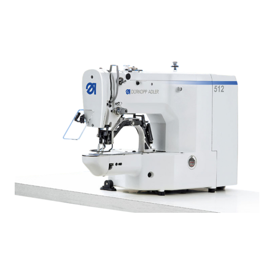
Technical Specifications 2 Technical Specifications The Dürkopp Adler 512 is a CNC double lockstitch bartack sewing machine. Die Dürkopp Adler 532 is a button sewing machine. 2.1 Characteristics of the 512 The existing programs are scalable and can be saved in this modified form. -
Page 14: Characteristics Of The 532
100 min steps. • Up to 10 user-defined button patterns can be programmed and stored. • A total of 50 button patterns can be stored under the 25 favorite buttons. Operating Manual 512/532 Version 00.0 - 12/2013... -
Page 15: Declaration Of Conformity
Y direction: 30 Number of standard patterns Number of storable modified patterns Number of sequences Number of seam appearances per sequence Soft start Can be switched Can be switched in and out in and out Operating Manual 512/532 Version 00.0 - 12/2013... - Page 16 Length, width, height [mm] 600 / 450 / 300 600 / 450 / 300 (controller incl. packaging) Weight (controller only) [kg] Dimensional data Class Voltage Frequency [Hz] 50 / 60 50 / 60 Power Operating Manual 512/532 Version 00.0 - 12/2013...
-
Page 17: Safety Information
Setup The power cable must have a plug authorized for the country in which the machine is being used. The power plug may only be connected to the power cable by a qualified specialist. Operating Manual 512/532 Version 00.0 - 12/2013... - Page 18 Safety equipment should not be removed or deactivated. If this Safety cannot be avoided for a repair operation, the safety equipment equipment must be refitted and put back into service immediately afterwards. Operating Manual 512/532 Version 00.0 - 12/2013...
-
Page 19: Signal Words And Symbols Used In Warnings
Symbols The following symbols indicate the type of risk to personnel: Symbol Type of danger General risk Risk of electric shock Risk of puncturing Risk of crushing Examples Examples of the layout of the warnings in the text: Operating Manual 512/532 Version 00.0 - 12/2013... - Page 20 Type and source of risk Consequences of non-observance Measures for avoiding the risk This is what a warning looks like for a hazard that could result in material damage if not complied with. Operating Manual 512/532 Version 00.0 - 12/2013...
- Page 21 Safety Information CAUTION Type and source of risk Consequences of non-observance Measures for avoiding the risk This is a warning note for a hazard that could result in environmental damage if not complied with. Operating Manual 512/532 Version 00.0 - 12/2013...
- Page 22 Safety Information Operating Manual 512/532 Version 00.0 - 12/2013...
-
Page 23: Operation
3. Pull the needle thread approx. 4 cm through the needle after threading. This ensures reliable sewing-on. 4. When using silicone oil, also thread the needle thread through the optional silicone oiler (1). Operating Manual 512/532 Version 00.0 - 12/2013... -
Page 24: Setting The Needle Thread Tension
1. Set the primary tension of the needle thread (2) to be as low as possible. The thread interlacing should be exactly in the middle of the material being sewn. With thin sewn material, excessive thread tension can lead to undesired ruffing and thread breakages. Operating Manual 512/532 Version 00.0 - 12/2013... -
Page 25: Setting The Thread Regulator
Risk of injury from needle and moving parts Only thread the needle thread with the sewing machine switched off. Figure 3: Setting the thread regulator ③ ① ② (1) – Thread regulator (3) – Screw (2) – Thread tensioning spring Operating Manual 512/532 Version 00.0 - 12/2013... -
Page 26: Winding The Hook Thread
Figure 4: Winding the hook thread ② ① ⑥ ⑤ ③ ④ (1) – Thread clamp (4) – Bobbin lever (2) – Bobbin (5) – Guide (3) – Winder shaft (6) – Tensioner Operating Manual 512/532 Version 00.0 - 12/2013... -
Page 27: Replacing The Hook Thread Bobbin
See 5.9 Bobbin winding, p. 40 4.5 Replacing the hook thread bobbin CAUTION Risk of injury from needle and moving parts Only thread the hook thread bobbin with the sewing machine switched off. Operating Manual 512/532 Version 00.0 - 12/2013... - Page 28 3. Pull the hook thread approx. 2.5 cm out of the bobbin housing upper (2). The bobbin must rotate in the direction of the arrow when pulling out the hook thread. 4. Insert the bobbin housing upper (2). 5. Close the hook cover (3). Operating Manual 512/532 Version 00.0 - 12/2013...
-
Page 29: Setting The Hook Thread Tension
1. Remove the bobbin housing upper section (3) with the bobbin. 2. Adjust the tensioning spring (1) via the adjustment screw (2) until the correct tension is set. 3. Insert the bobbin housing upper section (3). Operating Manual 512/532 Version 00.0 - 12/2013... -
Page 30: Changing Needle
(see Service manual). Otherwise the following errors can occur: • Changing to a thinner needle: Missing stitches, thread damage • Changing to a thicker needle: Damage to the hook tip, damage to the needle Operating Manual 512/532 Version 00.0 - 12/2013... -
Page 31: Adjusting The Button Mount Of The Button Clamp (Class 532)
Only change needles with the sewing machine switched off. Figure 8: Adjusting the button mount – standard clamp ④ ① ③ ② (1) – Button mount, left (3) – Knurled screw (2) – Lever (4) – Button mount, left Operating Manual 512/532 Version 00.0 - 12/2013... - Page 32 3. Press the Ready button. Clamp remains raised, pedal is disabled. 4. Loosen the knurled screw (3). 5. Open the button amount to the correct distance using the lever (2). 6. Insert the button. Operating Manual 512/532 Version 00.0 - 12/2013...
-
Page 33: Shank Shaper (Optional)
1. Manually swing the pivoting lever (2) with shank shaper (3) in and out, with the button clamp raised. Setting the shank length 1. Turn the adjusting screw (1): • Clockwise = Shank becomes longer. • Counterclockwise = Shank becomes shorter. Operating Manual 512/532 Version 00.0 - 12/2013... -
Page 34: Sewing
The sewing machine stops. The clamps remain lowered. Continuing the sewing Press the pedal briefly fully forwards or press process in the middle the Reset button. of the sewing cycle Operating Manual 512/532 Version 00.0 - 12/2013... -
Page 35: Customer Service
4.11 Customer service Contact for repairs if machine is damaged: Dürkopp Adler AG Potsdamer Str. 190 33719 Bielefeld Tel. +49 (0) 180 5 383 756 Fax +49 (0) 521 925 2594 Email: service@duerkopp-adler.com Internet: www.duerkopp-adler.com Operating Manual 512/532 Version 00.0 - 12/2013... - Page 36 Operation Operating Manual 512/532 Version 00.0 - 12/2013...
-
Page 37: Settings Via The Software
Needle thread clamp button with LED Clamps the needle thread on the first stitch. LED on = Needle thread clamp on LED off = Needle thread clamp off Memory button Perform memory functions. Operating Manual 512/532 Version 00.0 - 12/2013... -
Page 38: Switching On The Sewing Machine
Save the seam appearance. 5.2 Switching on the sewing machine 1. Main power switch ON. The last seam appearance sewn is loaded and the seam appearance number is shown in the Program display. Operating Manual 512/532 Version 00.0 - 12/2013... -
Page 39: Referencing The Machine
1. Press the Select button until the X axis symbol LED illuminates. 2. Press the +/– Function buttons until the desired X axis value is reached. 100 % corresponds to the specified dimensions of the selected seam appearance. Operating Manual 512/532 Version 00.0 - 12/2013... -
Page 40: Scaling The Y Axis
The button hole clearance is preset to 3.4 mm (3.4 mm = 100 %). The button hole clearance can be set by changing the percentage value. Button hole Button hole Button hole Value [%] Value [%] Value [%] clearance [mm] clearance [mm] clearance [mm] Operating Manual 512/532 Version 00.0 - 12/2013... -
Page 41: Recalculate The Bartack Dimensions (Class 512)
4. Press the +/– Function buttons to sew 1 stitch respectively. The Function display shows the current number of stitches. 5. Press the Reset button. The clamp raises. 6. Press the Select button until the Seam appearance form symbol LED illuminates. Operating Manual 512/532 Version 00.0 - 12/2013... -
Page 42: Changing The Seam Appearance
5. Press the pedal forwards. The bobbin winding process starts. 6. Press the pedal fully forwards to stop the bobbin winding process. 7. Press the Ready button. The button LED goes out, the clamp raises. Operating Manual 512/532 Version 00.0 - 12/2013... -
Page 43: Sewing
Each end of sewing decrements the counter by 1. A message is shown in the display when the cycle number is reached. 4. Insert a new bobbin. 5. Press the Reset button. Counter is reset. Operating Manual 512/532 Version 00.0 - 12/2013... -
Page 44: Pausing Sewing
The memory locations are called up via the +/– Function buttons, the memory locations up to number 25 can also be called up using single seam appearance buttons and combinations of these. Operating Manual 512/532 Version 00.0 - 12/2013... -
Page 45: Assigning The Memory Buttons
• Press the Select button until the Y axis symbol LED flashes. • Press the +/– Function buttons and set the values: –4 /+4. 8. Press the Ready button to confirm the settings. Operating Manual 512/532 Version 00.0 - 12/2013... -
Page 46: Sewing With The Memory Buttons
3. Press the Ready button to save the seam appearance sequence. 4. Press the +/– Function buttons to sew the 1 seam appearance. 5. Press the +/– Function buttons to sew the 2nd seam Operating Manual 512/532 Version 00.0 - 12/2013... -
Page 47: Sewing With A Seam Appearance Sequence
• Machine is in programming mode, Ready button LED is off. 1. Press the Memory button and button P3 at the same time. 2. Press the +/– Program buttons to select a seam appearance Operating Manual 512/532 Version 00.0 - 12/2013... -
Page 48: Finishing Sewing
• Machine is in programming mode, Ready button LED is off. 1. Press and hold the Memory button for 3 s. The controller beeps once, the button LED lights up. The Program display shows the parameter number, the Operating Manual 512/532 Version 00.0 - 12/2013... -
Page 49: Editing Parameters At The M2 Level
5. Press the Reset button to return a changed value to the original value. 6. Press the Ready button to save a change. The button LED goes out. 7. Press the Memory button. The button LED goes out. Operating Manual 512/532 Version 00.0 - 12/2013... -
Page 50: Resetting Parameters To Factory Defaults
2. Use the +/– Program buttons to set parameter number U085. 3. Press the Ready button. 4. Use the +/– Function buttons to enter a function value of 1. Press the Select button. Operating Manual 512/532 Version 00.0 - 12/2013... -
Page 51: Externally Editing Seam Appearances
To subsequently relocate the seam appearance, see 5.14 Saving seam appearances, p. 42. Figure 12: Sample stitch appearance coordinates in MS Excel or a text editor ① ② (1) – Starting point/first stitch (2) – End point/last stitch Operating Manual 512/532 Version 00.0 - 12/2013... - Page 52 • File name: HSR2000 ~ HSR2099 • File format: .CSV 3. Store the file on a USB stick. Information It is also possible to create seam appearances using DA-CAD 5000 and save these as CSV files. Operating Manual 512/532 Version 00.0 - 12/2013...
-
Page 53: Working With A Usb Stick
3. Press the Select button to load the seam appearance from the USB stick. The Function display shows the value ok,the controller beeps and the seam appearance is now saved. 4. Press the Reset button twice. Operating Manual 512/532 Version 00.0 - 12/2013... - Page 54 3. Use the +/– Function buttons to set the coordinates of the stitch for the X axis. 4. Press the Select button. The Y axis symbol LED illuminates, the Function display shows the value for the Y axis. Operating Manual 512/532 Version 00.0 - 12/2013...
-
Page 55: Error Messages
• Check the ROM. data error Pause Reset button pressed while • Press the Reset button. sewing. • Trigger the thread cutter. Sewing machine stopped. • Start the sewing process anew. Operating Manual 512/532 Version 00.0 - 12/2013... - Page 56 Own seam Read error U01 ~ U10 • Check the file type. appearances file error Own seam Read error U01 ~ U10 • Check the file type. appearances file error Operating Manual 512/532 Version 00.0 - 12/2013...
- Page 57 • Main power switch OFF. search error responding • Check the sensor. Clamp foot Clamp foot motor not • Main power switch OFF. motor error running correctly • Check the motor and connections. Operating Manual 512/532 Version 00.0 - 12/2013...
-
Page 58: Loading Software From A Usb Stick
When a new software version is available, this can be downloaded from www.duerkopp-adler.com and loaded into the controller via a USB stick. Important The following files must be stored on the USB stick: • FUYSTS.BT • LEEYSTS.BT1 • BT1mot • BT1PAT Operating Manual 512/532 Version 00.0 - 12/2013... -
Page 59: Loading The Main Program
5. Press the P5 button. The download into the controller starts. Duration is approx. 4 min. 6. Press the Reset button. 7. Pull out the USB stick. The software transfer is complete. Operating Manual 512/532 Version 00.0 - 12/2013... -
Page 60: Setting Parameter U085 (Class 532)
• A X.XX = Seam appearances 4. Press the +/– Function buttons and check the respective software version. 5. Press the Ready button. 6. Press the Memory button. The button LED goes out. Operating Manual 512/532 Version 00.0 - 12/2013... -
Page 61: Maintenance
NEVER blow particles towards other persons. The maintenance work must be performed according to the prescribed maintenance intervals. Shorter maintenance intervals may be required if sewing very fluffy material. A clean sewing machine provides protection from faults. Operating Manual 512/532 Version 00.0 - 12/2013... - Page 62 • Area under the throat plate (1) air pistol ). • Area around the hook (2) • Bobbin housing and interior • Thread cutter • Area around the needle Control cabinet Keep the fan grill clear Operating Manual 512/532 Version 00.0 - 12/2013...
-
Page 63: Lubrication
ALWAYS observe the legally prescribed regulations for handling and disposal of mineral oil. Take care to ensure that oil is NEVER spilt. Figure 16: Refilling oil ② ① (1) – Oil reservoir (2) – Oil filler opening Operating Manual 512/532 Version 00.0 - 12/2013... - Page 64 DA-10 can be obtained from DÜRKOPP ADLER AG sales offices using the following part number: • 250 ml container: 9047 000011 • 1 liter container: 9047 000012 • 2 liter container: 9047 000013 • 5 liter container: 9047 000014 Operating Manual 512/532 Version 00.0 - 12/2013...
- Page 65 Maintenance Figure 17: Lubrication I ① ① ① ① (1) – Lubrication points Operating Manual 512/532 Version 00.0 - 12/2013...
- Page 66 • Fill with oil through the oil filler opening (2) up to the A marking. Lubricating the sewing Lubricate the illustrated positions (1) of the 1000 machine sewing machine with special grease. Operating Manual 512/532 Version 00.0 - 12/2013...
-
Page 67: Seam Appearances
Seam appearances 7 Seam appearances 7.1 Standard seam appearances for class 512 Number of Stitch diagram Size (mm) X x Y stitches 16 x 2 10 x 2 16 x 2.5 24 x 3 10 x 2 16 x 2 10 x 2 16 x 2.5... - Page 68 Size (mm) X x Y stitches 8 x 2 8 x 2 10 x 0.1 10 x 0.1 25 x 0.1 25 x 0.1 25 x 0.1 35 x 0.1 4 x 20 Operating Manual 512/532 Version 00.0 - 12/2013...
- Page 69 0.1 x 20 0.1 x 10 0.1 x 20 0.1 x 20 10 x 7 12 x 7 10 x 6 12 x 6 7 x 10 7 x 10 24 x 3 Operating Manual 512/532 Version 00.0 - 12/2013...
- Page 70 Stitch diagram Size (mm) X x Y stitches 8 x 2 Ø 12 2.5 x 20 2.5 x 25 2.5 x 25 2.5 x 30 2.5 x 30 2.5 x 30 Ø 8 Operating Manual 512/532 Version 00.0 - 12/2013...
-
Page 71: Standard Seam Images For Class 532
15 / 42 6 - 6 3.4 x 3.4 32 / 50 5 - 5 - 5 3 x 2.5 16 / 43 8 - 8 8 - 8 - 8 10 - 10 Operating Manual 512/532 Version 00.0 - 12/2013... - Page 72 Seam appearances Operating Manual 512/532 Version 00.0 - 12/2013...
-
Page 73: Setup
1. Remove the following transport securing devices: • Lashing straps and wooden blocks from the upper machine section • Lashing straps and wooden blocks from the table plate • Lashing straps and wooden blocks from the frame. Operating Manual 512/532 Version 00.0 - 12/2013... -
Page 74: Assembly
(see Appendix). 8.3.2 Assembling the frame Figure 19: Assembling the frame ① ② ③ (1) – Adjusting screw (3) – Frame brace (2) – Pedal Operating Manual 512/532 Version 00.0 - 12/2013... -
Page 75: Completing The Table Plate
2. Screw the main power switch (3) to the left of the underside of the table plate. 3. Fasten the cables (1) and (2) to the control cabinet (5) on the table plate, using cable fastening nails and strain-relief clamps. Operating Manual 512/532 Version 00.0 - 12/2013... -
Page 76: Mounting The Upper Section Support
Mounting the upper section support Figure 22: Mounting the upper section support ① ② (1) – Upper section support (2) – Hole 1. Insert the upper section support (1) into the hole (2) in the table plate. Operating Manual 512/532 Version 00.0 - 12/2013... -
Page 77: Setting The Working Height
2. To avoid jamming, slide the table plate in or out evenly at both sides. The scales (1) on the outer sides of the bars serve as an adjustment aid. 3. Tighten both screws (2). Operating Manual 512/532 Version 00.0 - 12/2013... -
Page 78: Mounting Upper Machine Section
1. Place the sewing machine (3) on the table plate. 2. Fasten the sewing machine (3) at the left and right using the retainers (1) and (2). Screw the retainers in place using the screws (4), hanger (5) and nuts. Operating Manual 512/532 Version 00.0 - 12/2013... -
Page 79: Fitting The Oil Collection Reservoir
2. Screw the oil collection reservoir (5) into the retainer (2). 3. Pug the oil line (3) into the oil collection reservoir (5). 4. Plug the rubber mounts (4) into the table plate (6). Operating Manual 512/532 Version 00.0 - 12/2013... -
Page 80: Electrical Connection
2. Lay the cables to the control cabinet and bundle together with cable ties. 3. Connect the cable plugs. 4. Screw the equipotential bonding cables on the control cabinet to the positions marked with earthing symbols. Operating Manual 512/532 Version 00.0 - 12/2013... -
Page 81: Mount The Hood
8.3.12 Fit the eye protection Figure 28: Fit the eye protection ② ① (1) – Eye protection (2) – Screw 1. Screw the eye protection (2) to the upper section using 2 screws (1). Operating Manual 512/532 Version 00.0 - 12/2013... -
Page 82: Fit The Button Container (Class 532)
(1) – Screw (3) – Button container (2) – Retainer 1. Screw the retainer (2) to the table plate. 2. Plug the button container (3) into the retainer (2) and secure with a screw (1). Operating Manual 512/532 Version 00.0 - 12/2013... -
Page 83: Sewing Test
9. Start the sewing test at low speed and then continuously increase the speed. 10. Check that the seams conform to the desired requirements. If not, see 4.2 Setting the needle thread tension, p. 22. Operating Manual 512/532 Version 00.0 - 12/2013... - Page 84 Setup Operating Manual 512/532 Version 00.0 - 12/2013...
-
Page 85: Disposal
ALWAYS observe the legally prescribed regulations for disposal of oil. When disposing of the machine, be aware that it consists of a range of different materials (steel, plastic, electronic components, etc.). Observe the applicable national regulations for disposal. Operating Manual 512/532 Version 00.0 - 12/2013... - Page 86 Disposal Operating Manual 512/532 Version 00.0 - 12/2013...
-
Page 87: Appendix
Appendix 10Appendix Operating Manual 512/532 Version 00.0 - 12/2013... - Page 88 Appendix Operating Manual 512/532 Version 00.0 - 12/2013...
- Page 90 DÜRKOPP ADLER AG Potsdamer Straße 190 33719 Bielefeld GERMANY Phone +49 (0) 521 / 925-00 E-mail marketing@duerkopp-adler.com www.duerkopp-adler.com...