
Related Manuals for Panasonic KT4R


Summary of Contents for Panasonic KT4R
- Page 1 Phone: 800.894.0412 - Fax: 888.723.4773 - Web: www.clrwtr.com - Email: info@clrwtr.com...
- Page 2 Temperature controllers KT4R / KT8R / KT9R. This User’s Manual contains instructions for mounting, functions, operations and notes when operating the KT4R, KT8R, KT9R. To prevent accidents arising from the misuse of this controller, please ensure the operator receives this manual.
- Page 3 • To ensure safe and correct use, thoroughly read and understand this manual before using this instrument. • Panasonic Industrial Devices SUNX Co., Ltd. is not liable for any damage or secondary damage(s) incurred as a result of using this product, including any indirect damage.
- Page 4 • Tighten the terminal screw using the specified torque. If excessive force is applied to the screw when tightening, the terminal screw or case may be damaged. • When using a terminal cover for the KT4R, pass terminal wires numbered 7 to 12 into the holes of the terminal cover.
-
Page 5: Table Of Contents
Contents Page 1. Model Number 1.1 Model Number -------------------------------------------------------------------------- 7 1.2 How to Read the Rated Label ------------------------------------------------------ 7 2. Names and Functions of Sections ------------------------------------------------- 8 3. Mounting to the Control Panel 3.1 External Dimensions (Scale: mm) ----------------------------------------------- 10 3.2 Panel Cutout (Scale: mm) --------------------------------------------------------- 12 3.3 Mounting to, and Removal from, the Control Panel 3.3.1 How to Mount the Unit ---------------------------------------------------------- 13... - Page 6 9. Attached Function 9.1 Input Value Correction -------------------------------------------------------------- 85 9.2 Set Value Lock ------------------------------------------------------------------------ 87 9.3 Control Output OFF Function ------------------------------------------------------ 88 9.4 Switching Auto/Manual Control (Auto/Manual Control Function) --------- 89 9.5 Using as a Converter ---------------------------------------------------------------- 90 9.6 Clearing Data -------------------------------------------------------------------------- 92 9.7 2DOF PID control --------------------------------------------------------------------- 92 10.
-
Page 7: Model Number
1: 1 point (Relay contact 1a),2: 2 points (Relay contact 1a) (6) Serial communication (*) Blank: Not available 1: RS-485 Serial communication (※) Only for the KT4R model 1.2 How to Read the Rated Label The rated label is attached to the case. -
Page 8: Names And Functions Of Sections
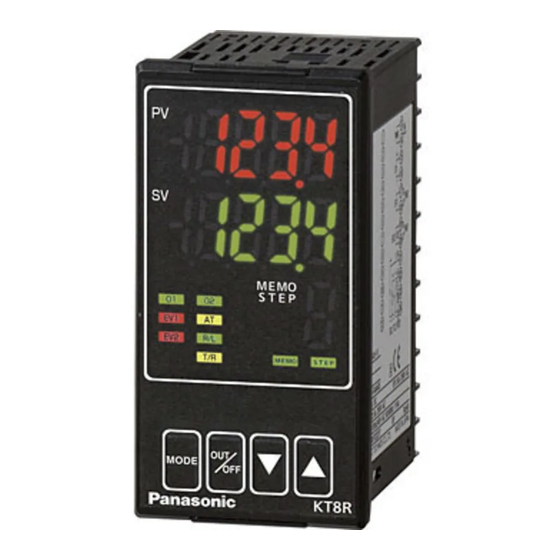
2. Names and Functions of Sections KT4R (Fig. 2-1) KT8R KT9R (Fig. 2-2) (Fig. 2-3) Display Name Description PV Display Indicates PV. Indicates setting characters in each setting mode. SV Display Indicates SV. Indicates set data in each setting mode. - Page 9 Action Indicators Name Description O1 (Green) Lit when control output OUT1 is ON. For direct current output type, flashes corresponding to the MV in 125 ms cycles. O2 (Yellow) Lit when control output OUT2 is ON. When (Heating/Cooling control relay contact output) is selected in [Event output EV2 allocation] EV1 (Red) Lit when Event output 1 is ON.
-
Page 10: Mounting To The Control Panel
3. Mounting to the Control Panel 3.1 External Dimensions (Scale: mm) KT4R Mounting frame Terminal cover (sold separately) Rubber gasket (*) When the terminal cover is used. (Fig. 3.1-1) KT8R Screw type mounting bracket Screw type mounting bracket Rubber gasket... - Page 11 KT9R Screw type mounting bracket Terminal cover (sold separately) Rubber gasket (*) When terminal covers are used. (Fig. 3.1-3) Phone: 800.894.0412 - Fax: 888.723.4773 - Web: www.clrwtr.com - Email: info@clrwtr.com...
-
Page 12: Panel Cutout (Scale: Mm)
3.2 Panel Cutout (Scale: mm) Caution If lateral close mounting is used for the unit, IP66 specification (Water-proof/Dust-proof) may be compromised, and all warranties will be invalidated. KT4R Lateral close mounting n: Number of units mounted (Fig. 3.2-1) KT8R +0.5 n×48-3... -
Page 13: Mounting To, And Removal From, The Control Panel
3.3 Mounting to, and Removal from, the Control Panel Caution As the mounting frame of the KT4R is made of resin, do not use excessive force while tightening screws, or the mounting frame could be damaged. Tighten screws with one rotation upon the screw tips touching the panel. - Page 14 KT8R, KT9R Mount the controller vertically to the flat, rigid panel to ensure it adheres to the Water-proof/ Dust-proof specification (IP66). If the lateral close mounting is used for the controller, IP66 specification (Water-proof/Dust-proof) may be compromised, and all warranties will be invalidated. Mountable panel thickness: 1 to 7 mm (1) Insert the controller from the front side of the control panel.
-
Page 15: How To Remove The Mounting Frame And Unit
3.3.2 How to Remove the Mounting Frame and Unit KT4R (Fig. 3.3.2-1) (1) Turn the power to the unit OFF, and disconnect all wires before removing the mounting frame. (2) Insert a flat blade screwdriver between the mounting frame and unit (... -
Page 16: Wiring
Turn the power supply to the instrument off before wiring or checking. Working on or touching the terminal with the power switched on may result in severe injury or death due to electric shock. 4.1 Terminal Arrangement KT4R (Fig. 4.1-1) KT8R, KT9R (Fig. 4.1-2) -
Page 17: Lead Wire Solderless Terminal
: + side of 0 to 1 V DC RS-485 Serial communication RS-485 Serial communication can be specified only for the KT4R model. 4.2 Lead Wire Solderless Terminal Use a solderless terminal with an insulation sleeve in which an M3 screw fits as shown below. -
Page 18: Terminal Cover
4.3 Terminal Cover KT4R When using a terminal cover (sold separately), make sure the longer side is on the back right side of the case. Pass the wires from terminals 7 to 12 into the holes of the terminal cover. - Page 19 KT9R When using terminal covers (sold separately), make sure the longer side is on the back right and left sides of the case. Pass the wires from terminals 13 to 24 through between covers. Top of KT9R 2 terminal covers Mount the longer side of the cover to the back right and left.
-
Page 20: Wiring
Power supply voltage is 100 to 240 V AC or 24 V AC/DC. For a 24 V AC/DC power source, ensure polarity is correct when using direct current (DC). 24 V AC/DC is available only for the KT4R model. KT4R KT8R, KT9R 4.4.2 Control Output OUT1... -
Page 21: Input
Each input wiring is shown below. For DC voltage input, (+) side input terminal number of 0 to 5 V DC, 1 to 5 V DC, 0 to 10 V DC differs from that of 0 to 1 V DC. KT4R Direct current DC voltage... -
Page 22: Event Output 1
Electrical life: 100,000 cycles Minimum applicable load: 10 mA 5 V DC KT4R KT8R, KT9R 4.4.5 Serial Communication Serial communication can be specified only for the KT4R model. KT4R Phone: 800.894.0412 - Fax: 888.723.4773 - Web: www.clrwtr.com - Email: info@clrwtr.com... -
Page 23: Outline Of Key Operation And Each Mode
(*3) Integral 2DOF Current step coefficient (β) number (KT4R) [92] (*3) (*1) If ‘Program control’ is selected in [OUT/OFF key function], the unit enters Standby mode (program control waiting). (*2) The unit cannot proceed to Monitor mode if it is in Standby of program control. - Page 24 • (3 sec): Press and hold the keys (all keys) (in that order) together for approx. 3 sec. • (3 sec): Press and hold the keys (in that order) together for approx. 3 sec. • : Press and hold the keys (in that order) together.
-
Page 25: Modes
Indicated contents differ depending on the model number. Model number Indicated Contents KT4R Indicates MV, Remaining time (Program control) or Step number (Program control). KT8R, KT9R Indicates MV or Remaining time (Program control). -
Page 26: Basic Operation After Power-On
5.3 Basic Operation after Power-ON After the unit is mounted to the control panel and wiring is completed, operate the unit following the procedures below. (1) Turn the unit power supply ON ※After confirming the rated voltage, polarity and wiring, turn the power ON via contacts such as switch or relay. - Page 27 (3) Turn the load circuit power ON Control starts, so as to reach, and then maintain the control target at the SV. Error codes during operation If errors occur during operation, error codes below are indicated in the PV Display. Error Code Error Contents PV has exceeded Input range high limit value (scaling high limit value for DC...
- Page 28 [Output status when input errors occur] can be used only for controllers using Direct current input and voltage input, and Direct current output. Output status differs depending on selection in [Output status when input errors occur]. Output Status Output status Contents, OUT1 OUT2...
-
Page 29: Initial Settings
6. Initial Settings Setup (setting the Input type, Event output allocation, SV, etc.) should be done before using this controller, according to the user’s conditions. Perform setup in Initial setting mode. Setting items in Initial setting mode are shown in (Table 6.1). If the user’s specification is the same as the factory default value of this instrument, or if user’s instrument has already been installed in a system, initial settings are not necessary. -
Page 30: Example Of Initial Settings
6.1 Example of Initial Settings (e.g.) AKT4R111100 Initial Setting Items Example Input type K -200.0 to 400.0 Event output EV1 allocation High limit alarm EV1 alarm value 20.0 (Deviation setting from SV) 200.0 (Fixed value control) PID control is performed. PID constants are calculated by performing AT. Alarm action 200.0 219.0... - Page 31 Setting Procedure Setting Detail Power ON Power ON RUN mode RUN mode PV/SV Display (3 sec) Initial setting mode Initial setting mode Input type Input type [1] : K -200.0 to 400.0 (3 times) Event output EV1 Event output EV1 allocation. [5] allocation : High limit alarm (Twice)
-
Page 32: Initial Setting Mode
6.2 Initial Setting Mode To enter Initial setting mode, press and hold the keys (in that order) for 3 seconds in RUN mode. To set (or select) each setting item, use the key. To register each setting item, press the key. - Page 33 Characters, Setting Item, Function, Setting Range Factory Default Scaling high limit • Sets scaling high limit value. • Setting range: Scaling low limit value to Input range high limit value DC voltage, current inputs: -2000 to 10000 (*1) Scaling low limit •...
- Page 34 Characters, Setting Item, Function, Setting Range Factory Default Output by communication Turns OFF or ON by communication command command 00E4H during Serial communication. B0 EV1 output 0: OFF 1: ON B1 EV2 output 0: OFF 1: ON EV1 alarm value 0 Enabled/Disabled •...
- Page 35 Characters, Setting Item, Function, Setting Range Factory Default EV1 alarm hysteresis • Sets EV1 alarm hysteresis. • Setting range: 0.1 to 1000.0 DC voltage, current inputs: 1 to 10000 (*1) Available when any alarm from (Alarm output, High limit alarm) to (Alarm output, High/Low limits with standby independent alarm) is selected in [Event output EV1 allocation].
- Page 36 Characters, Setting Item, Function, Setting Range Factory Default Event output EV2 allocation • Selects Event output EV2 from the Event Output Allocation Table below. • When changing Event output EV2, refer to Section “8.10 Items to be Initialized by Changing Settings” (p.84). •...
- Page 37 Characters, Setting Item, Function, Setting Range Factory Default EV2 alarm value • Sets EV2 alarm value. EV2 alarm value matches EV2 low limit alarm value in the following cases: (Alarm output, High/Low limits independent alarm), (Alarm output, High/Low limit range independent alarm), or (Alarm output, High/Low limits with standby independent alarm) is selected in [Event output EV2 allocation].
- Page 38 Characters, Setting Item, Function, Setting Range Factory Default EV2 alarm Energized/De-energized • Selects Energized/De-energized status for EV2 alarm. (Refer to ‘EV1/EV2 Energized/De-energized’ on p.40.) • Selection item: Energized De-energized Available only when Event output EV2 is specified. Available when any alarm from (Alarm output, High limit alarm) to (Alarm output, High/Low limits with standby independent alarm) is selected in [Event output EV2 allocation].
- Page 39 Characters, Setting Item, Function, Setting Range Factory Default • Sets SV1. • Setting range: Scaling low limit to Scaling high limit (*1) Available when Control output OFF function or Auto/Manual control is selected in [OUT/OFF key function]. (*1) The placement of the decimal point follows the selection. Phone: 800.894.0412 - Fax: 888.723.4773 - Web: www.clrwtr.com - Email: info@clrwtr.com...
- Page 40 Loop break alarm (after the MV has reached 0% or the OUT low limit value), the alarm will be activated. If Serial communication is specified, status can be read by reading Status flag 1. Serial communication can be specified only for the KT4R model. Phone: 800.894.0412 - Fax: 888.723.4773 - Web: www.clrwtr.com - Email: info@clrwtr.com...
- Page 41 [Time Signal Output] Time signal output activates during Time signal output ON time within the step for which step number is set. Time signal output ON time follows Time signal output OFF time after the program control starts. The following program pattern shows that the temperature rises to 200 for 1 hour, and stays at 200 for 2 hours after Program control starts.
-
Page 42: Settings
7. Settings In this section, Main setting, Sub setting and Engineering mode 1 and 2 will be explained. 7.1 Main Setting Mode To enter Main setting mode, press the key in RUN mode. Use the key for settings (or selections). To register the set data, use the key. - Page 43 Characters, Setting Item, Function, Setting Range Factory Default [13] • Sets SV2. • Corresponds to [SV2] in Initial setting mode. If Program control is selected in [OUT/OFF key function], this will become Step 2 • Setting range: Scaling low limit to Scaling high limit (*1) Available only when Program control is selected in [OUT/OFF key function].
- Page 44 Characters, Setting Item, Function, Setting Range Factory Default [19] • Sets SV4. • Corresponds to [SV4] in Initial setting mode. If Program control is selected in [OUT/OFF key function], this will become Step 4 • Setting range: Scaling low limit to Scaling high limit (*1) Available only when Program control is selected in [OUT/OFF key function].
- Page 45 Characters, Setting Item, Function, Setting Range Factory Default [25] Step 6 SV • Sets Step 6 SV. • Setting range: Scaling low limit to Scaling high limit (*1) Available only when Program control is selected in [OUT/OFF key function]. Step 6 time [26] •...
- Page 46 Characters, Setting Item, Function, Setting Range Factory Default [31] Step 8 SV • Sets Step 8 SV. • Setting range: Scaling low limit to Scaling high limit (*1) Available only when Program control is selected in [OUT/OFF key function]. Step 8 time [32] •...
-
Page 47: Sub Setting Mode
7.2 Sub Setting Mode To enter Sub setting mode, press the keys (in that order) together in RUN mode. Use the key for settings (or selections). To register the set data, use the key. Explanation of setting items: • Upper left: PV Display: Indicates setting characters. •... - Page 48 Characters, Setting Item, Function, Setting Range Factory Default [41] • Sets ARW (anti-reset windup). • Setting range: 0 to 100% Available only for PID control. [42] Manual reset • Sets the reset value manually. • Setting range: Proportional band value If a value larger than 100.0% is set in [OUT1 proportional band], the setting range will be 100.0.
- Page 49 Characters, Setting Item, Function, Setting Range Factory Default [48] OUT2 cooling method • Selects OUT2 cooling method from air, oil or water cooling. OUT2 proportional band Air cooling Oil cooling Water cooling (Fig. 7.2-1) • Selection item: Air cooling (linear characteristics) Oil cooling (1.5th power of the linear characteristics) Water cooling (2nd power of the linear characteristics) Available only when...
- Page 50 Characters, Setting Item, Function, Setting Range Factory Default [53] OUT2 low limit • Sets OUT2 low limit value. • Setting range: 0% to OUT2 high limit value Available only when (Heating/Cooling control relay contact output) is selected in [Event output EV2 allocation] [54] Overlap/Dead band...
- Page 51 Characters, Setting Item, Function, Setting Range Factory Default [57] EV1 high limit alarm value • Sets EV1 high limit alarm value. This value is available only for the following cases: (Alarm output, High/Low limits independent alarm), (Alarm output, High/Low limit range independent alarm), or (Alarm output, High/Low limits with standby independent alarm) is selected in [Event output EV1 allocation].
- Page 52 [OUT1 rate-of-change] For Heating control, if PV is lower than SV, the output is generally turned from OFF to ON as shown in (Fig. 7.2-2). If OUT1 rate-of-change is set, the output can be changed by the rate-of-change (Fig. 7.2-3). This control is suitable for high temperature heaters (which are made from molybdenum, tungsten or platinum, etc., and used at approx.
-
Page 53: Engineering Mode
7.3 Engineering Mode 1 To enter Engineering mode 1, press and hold the keys (in that order) together for 3 seconds in RUN mode. Use the key for settings (or selections). To register the set data, use the key. Explanation of setting items: •... - Page 54 Characters, Setting Item, Function, Setting Range Factory Default [63] Event output EV1 allocation • Selects Event output EV1 from the Event Output Allocation Table below. Corresponds to [Event output EV1 allocation] in Initial setting mode. • When changing Event output EV1 allocation, refer to Section “8.10 Items to be Initialized by Changing Settings”...
- Page 55 Characters, Setting Item, Function, Setting Range Factory Default EV1 alarm value • Sets EV1 alarm value. Corresponds to [EV1 alarm value] in Initial setting mode. EV1 alarm value matches EV1 low limit alarm value in the following cases: (Alarm output, High/Low limits independent alarm), (Alarm output, High/Low limit range independent alarm), or (Alarm output,...
- Page 56 Characters, Setting Item, Function, Setting Range Factory Default EV1 alarm delay time • Sets EV1 alarm action delay time. Corresponds to [EV1 alarm delay time] in Initial setting mode. When setting time has elapsed after the input enters the alarm output range, the alarm is activated.
- Page 57 Characters, Setting Item, Function, Setting Range Factory Default [64] Event output EV2 allocation • Selects Event output EV2 from the Event Output Allocation Table below. Corresponds to [Event output EV2 allocation] in Initial setting mode. • When changing Event output EV2, refer to Section “8.10 Items to be Initialized by Changing Settings”...
- Page 58 Characters, Setting Item, Function, Setting Range Factory Default EV2 alarm value 0 Enabled/Disabled • When EV2 alarm value is 0 (zero), alarm action can be Enabled or Disabled. Corresponds to [EV2 alarm value 0 Enabled/Disabled] in Initial setting mode. • Selection item: Disabled Enabled Available only when Event output EV2 is specified.
- Page 59 Characters, Setting Item, Function, Setting Range Factory Default EV2 alarm hysteresis • Sets EV2 alarm hysteresis. Corresponds to [EV2 alarm hysteresis] in Initial setting mode. • Setting range: 0.1 to 1000.0 ( ), DC voltage, current inputs: 1 to 10000 (*1) Available only when Event output EV2 is specified.
- Page 60 MODBUS RTU MODBUS ASCII (KT command allocation) MODBUS RTU (KT command allocation) Available only when Serial communication is specified. Serial communication can be specified only for the KT4R model. [69] Instrument number • Sets the instrument number. The instrument numbers should be set one by one when multiple instruments are connected in Serial communication, otherwise communication is impossible.
- Page 61 • Selection item: 9600 bps 19200 bps 38400 bps Available only when Serial communication is specified. Serial communication can be specified only for the KT4R model. [71] Data bit/Parity • Selects data bit and parity. • Selection item: 8 bits/No parity...
- Page 62 Characters, Setting Item, Function, Setting Range Factory Default [75] Power restore action • Selects the program status if a power failure occurs mid-program and it is restored. • Selection item: Stops after power is restored. Continues (resumes) after power is restored. Suspends (on hold) after power is restored.
- Page 63 Characters, Setting Item, Function, Setting Range Factory Default [81] SV fall rate • Sets SV fall rate (falling value for 1 minute). When the SV is adjusted, it approaches the new SV by the preset rate-of-change ( /min, /min). When the power is turned on, the control starts from the PV and approaches the SV by the rate-of-change ( /min, /min).
- Page 64 Characters, Setting Item, Function, Setting Range Factory Default [88] Indication time • Sets time from no operation status until Displays are switched off. Displays relight by pressing any key while in OFF mode. When input error (Overscale, Underscale) or burnout has occurred, Displays are lit, and error codes are displayed.
-
Page 65: Engineering Mode
7.4 Engineering Mode 2 To enter Engineering mode 2, press and hold the keys (in that order) together for approximately 5 seconds in RUN mode. Use the key for settings (or selections). To register the set data, use the key. Explanation of setting items: •... -
Page 66: Operation And Settings Of Standard Functions
8. Operation and Settings of Standard Functions 8.1 Selecting an input type Select an input type in [Input type] in Initial setting mode. Selection item: -200 to 1370 -328 to 2498 -200.0 to 400.0 -328.0 to 752.0 -200 to 1000 -328 to 1832 0 to 1760 32 to 3200... -
Page 67: Selecting Pid Control Or On/Off Control
8.2 Selecting PID Control or ON/OFF Control Selects PID or ON/OFF control action. Select PID or ON/OFF control action in [OUT1 proportional band] in Sub setting mode. If ‘OUT1 proportional band’ is set to 0 (zero), the unit performs ON/OFF control action. Factory default value is PID control. -
Page 68: Selecting Direct/Reverse Action
8.3 Selecting Direct/Reverse Action Selects Direct or Reverse control action. Select Direct or Reverse control action in [Direct/Reverse action] in Sub setting mode. Factory default value is Reverse action. Direct action In Direct action, MV is increased when PV is higher than SV (positive deviation). Refrigerators, etc. -
Page 69: Performing Fixed Value Control
8.4 Performing Fixed Value Control Fixed value control is a typical temperature control action, which reduces deviation from a single SV by comparing with PV. To perform Fixed value control, set the SV. There are 2 ways to set the SV. •... -
Page 70: Setting Pid Constants (By Performing At)
8.5 Setting PID Constants (by Performing AT) Notice • Perform the AT during the trial run. • During the AT, none of the setting items can be set. • If power failure occurs during the AT, the AT stops. • If AT is cancelled during the process, P, I, D and ARW values revert to the values before AT was performed. - Page 71 [C] If there is a large difference between the SV and PV as the temperature is falling When AT bias is set to 20 , the AT process will fluctuate at the temperature 20 higher than the SV. Temperature 20 higher than the SV Temperature (1) Calculating PID constants...
- Page 72 However, if PV slope and delay time cannot be measured normally for P, I, D calculation, the error code below will be indicated in the PV display, and automatically ‘AT on startup’ will stop. If an error has occurred, P, I, D and ARW values revert to the previous value at which ‘AT on startup’ is performed.
-
Page 73: Performing Auto-Reset
8.6 Performing Auto-reset Notice • Auto-reset is cancelled in approximately 4 minutes. It cannot be cancelled while performing this function. • If input is burnt out, Auto-reset will be forced to stop. Auto-reset is performed to correct the offset at the point at which PV indication is stabilized within the proportional band during the PD control. -
Page 74: Performing Program Control
8.7 Performing Program Control In Program control, SV changes as time elapses, and PV is controlled in order to reach each SV. SV and time can be set for every step, and a maximum of 9 steps can be repeatedly controlled. SV can be set as (Fig. - Page 75 Program control Holding/Not holding can be selected by communication command bit operation in Serial communication. Serial communication can be specified only for the KT4R model. Advance function Interrupts current step while Program control is running, and proceeds to the beginning of the next step.
- Page 76 Program start temperature When Program control starts, it starts from the value set in [Program start temperature]. Factory default value is 0 . Program control start type One type can be selected: PV start, PVR start, SV start. Factory default value is PV start. Program control Description start type...
- Page 77 Select ‘Program control’ in [OUT/OFF key function] in Engineering mode 1. Factory default value is Control output OFF function. Set the following items in Engineering mode 1 if necessary: Step time unit, Power restore action, Program start temperature, Program control start type, Number of repetitions Program pattern can be set in Main setting mode.
- Page 78 (Example) Selecting Program control and Setting program pattern of (Fig. 8.7-6) Power ON RUN mode PV/SV Display (3 sec) Engineering mode 1 Set value lock [62] (Many times) OUT/OFF key function [86] Select (Program control). (Many times) or (3 sec) RUN mode Standby (Program control waiting) Main setting mode...
- Page 79 Step 2 wait value [15] Set to 0 . Step 3 SV [16] Set to 300 Step 3 time [17] Set to 0:30. Step 3 wait value [18] Set to 10 . Step 4 SV [19] Set to 300 . Step 4 time [20] Set to 1:00.
- Page 80 Step 5 time [23] Set to 2:00. Step 5 wait value [24] Set to 0 . (Many times) or (3 sec) RUN mode Standby (program control waiting) mode Now, selection is complete. Program control RUN To perform Program control, press and hold the key for approx.
-
Page 81: Event Output Ev1 Allocation
8.8 Event Output EV1 Allocation Selects Event output EV1 allocation. There are 2 methods in selection of Event output EV1 allocation. • Select in [Event output EV1 allocation] in Initial setting mode. • Select in [Event output EV1 allocation] in Engineering mode 1. Setting item [Event output EV1 allocation] in Initial setting mode corresponds to [Event output EV1 allocation] in Engineering mode 1. - Page 82 (Example) Selecting High limit alarm, and setting EV1 alarm value to 20 Power ON RUN mode PV/SV Display (3 sec) Initial setting mode Input type [1] (3 times) Event output EV1 allocation [5] Select (High limit alarm). (2 times) EV1 alarm value [B] Set to 20 .
-
Page 83: Indicating Mv, Remaining Time (Program Control)
Monitor mode Indicates MV. (e.g.) MV: 7.2% (Decimal point flashes.) Remaining time (Program control RUN) (e.g.) Remaining time 0:30 Step number (Program control RUN) (KT4R) (e.g.) Step 1 RUN mode PV/SV Display Phone: 800.894.0412 - Fax: 888.723.4773 - Web: www.clrwtr.com - Email: info@clrwtr.com... -
Page 84: Items To Be Initialized By Changing Settings
8.10 Items to be Initialized by Changing Settings If settings are changed, the following items will be initialized. Yes: Initialized No: Not initialized Setting item to be Event output Event output Transmission Item changed Input Type EV1 allocation EV2 allocation output to be Initialized SV1 to SV9... -
Page 85: Attached Function
9. Attached Function 9.1 Input Value Correction Input value can be corrected in [Sensor correction coefficient] and [Sensor correction] in Engineering mode. In [Sensor correction coefficient], set the slope of temperature change. In [Sensor correction], set the difference between temperatures before correction and after correction. PV after input correction is expressed with the following formula. - Page 86 (Example) Setting Sensor correction coefficient to 0.800, and Sensor correction to 100.0 Power ON RUN mode PV/SV Display (3 sec) Engineering mode 1 Set value lock [62] (Many times) Sensor correction coefficient. [65] Set to 0.800. Sensor correction [66] Set to 100.0 . (Many times) or (3 sec) RUN mode...
-
Page 87: Set Value Lock
9.2 Set Value Lock Locks the set values to prevent setting errors. Make a selection in [Set value lock] in Engineering mode 1. The setting item to be locked depends on the selection. Selection Item Change via Keypad Change via Software Communication Unlock All set values can be changed. -
Page 88: Control Output Off Function
9.3 Control Output OFF Function The control action and output of an instrument (or instruments) can be turned OFF without turning OFF their power supplies using this function. Select ‘Control output OFF function’ in [OUT/OFF key function] in Engineering mode 1. Factory default value is Control output OFF function. -
Page 89: Switching Auto/Manual Control (Auto/Manual Control Function)
9.4 Switching Auto/Manual Control (Auto/Manual Control Function) Control action can be switched from automatic to manual and vice versa. When power to the controller is turned ON, Automatic or Manual control is selectable. Select ’Auto/Manual control’ in [OUT/OFF key function] in Engineering mode 1. Factory default value is Control output OFF function. -
Page 90: Using As A Converter
9.5 Using as a Converter This instrument can be used as a simplified converter. Converts each input value (thermocouple, RTD, DC voltage and current inputs) to ‘4 to 20 mA DC’, and outputs it. When OUT1 is Direct current output, the controller can be used as a converter. Select ‘Converter’... - Page 91 (Example) Selecting Converter Power ON RUN mode PV/SV Display (3 sec) Engineering mode 1 Set value lock [62] (Many times) Controller/Converter [89] Available only when OUT1 is Direct current output. Select (Converter). RUN mode [Unlit] Converter Now, selection is complete. Phone: 800.894.0412 - Fax: 888.723.4773 - Web: www.clrwtr.com - Email: info@clrwtr.com...
-
Page 92: Clearing Data
9.6 Clearing Data If data is cleared, data will revert to factory default values. To clear data, press and hold (in that order) together for approx. 3 seconds in the PV/SV Display. The unit enters [Data clear Yes/No] mode. Select ‘Yes’, and press the key. -
Page 93: Action Explanation
10. Action Explanation 10.1 OUT1 Action Reverse (Heating) action Direct (Cooling) action Proportional band Proportional band Contro action Relay contact output Cycle action is performed Cycle action is performed according to deviation. according to deviation. Non-contact 12 V DC 0 V DC 0/12 V DC 12/0 V DC 0 V DC... -
Page 94: Alarm Action
10.3 Alarm Action High limit alarm Low limit alarm EV1 hysteresis EV1 hysteresis Alarm action -EV1 value +EV1 value -EV1 value +EV1 value +side +side Alarm output - side - side High/ Low limits alarm High/ Low limits independent alarm EV1 hysteresis EV1 hysteresis Alarm... - Page 95 Low limit with standby alarm High limit with standby alarm EV1 hysteresis EV1 hysteresis Alarm action -EV1 value +EV1 value -EV1 value +EV1 value +side + side Alarm output - side - side High/Low limits with standby alarm H/L limits with standby independent alarm EV1 hysteresis EV1 hysteresis Alarm...
-
Page 96: Out2 (Heating/Cooling Control) Action
10.4 OUT2 (Heating/Cooling Control) Action Heating P-band (Cooling P-band) Control Heating (Cooling action control control) Relay contact output (OUT1) Cycle action is performed according to deviation Non- contact voltage output 12V DC 12/0 V DC 0 V DC (OUT1) Cycle action is performed according to deviation Direct current 20 mA DC... -
Page 97: Out2 (Heating/Cooling Control) Action (When Setting Dead Band)
10.5 OUT2 (Heating/Cooling Control) Action (When Setting Dead Band) (Cooling P-band) Heating P-band Dead band Control Heating (Cooling action control Control) Relay contact output (OUT1) Cycle action is performed according to deviation Non- contact 12 V DC 12/0 V DC 0 V DC voltage output (OUT1) -
Page 98: Out2 (Heating/Cooling Control) Action (When Setting Overlap Band)
10.6 OUT2 (Heating/Cooling Control) Action (When Setting Overlap Band) Heating P-band Cooling P-band Overlap band Control Heating (Cooling action control control) Relay contact output (OUT1) Cycle action is performed according to deviation Non-contact 12 V DC 12/0 V DC 0 V DC voltage output (OUT1) Cycle action is performed... -
Page 99: Specifications
Allowable signal source resistance: 100 max. Power 100 to 240 V AC 50/60 Hz supply 24 V AC/DC 50/60 Hz (24 V AC/DC can be specified only for the KT4R model.) voltage Allowable 85 to 264 V AC voltage 20 to 28 V AC/DC fluctuation Phone: 800.894.0412 - Fax: 888.723.4773 - Web: www.clrwtr.com - Email: info@clrwtr.com... - Page 100 General Structure External KT4R 48 x 48 x 68 mm (W x H x D) (Depth of control panel interior: 60) KT8R dimensions 48 x 96 x 68 mm (W x H x D) (Depth of control panel interior: 60)
- Page 101 Setting Structure Function UP key Increases the numeric value. By pressing this key for 1 second during Program control, the performing step is interrupted, proceeding to the beginning of the next step. (Advance function) DOWN key Decreases the numeric value. Selects a setting mode, or registers the set data.
- Page 102 Control Relay contact Control capacity: 3 A 250 V AC (resistive load) output 1 A 250 V AC (inductive load cos =0.4) Electrical life: 100,000 cycles Minimum applicable load: 10 mA 5 V DC Non-contact 12 V DC 15% voltage Max 40 mA (short circuit protected) (For SSR drive) Direct current...
- Page 103 Simplified converter If ‘Converter’ is selected in [Controller/Converter], this instrument can function be used as a converter, by setting the following items. Setting Item Values or Selection Scaling low limit value AT/Auto-reset Perform/Cancel AT/AT on startup/Auto-reset Cancel OUT1 proportional band Scaling span Direct current, voltage inputs: 100.0% Integral time...
- Page 104 24 V DC Approx. 5 W max. (8 W max. when EV2 and Serial communication are added) (*) 24 V AC/DC can be specified only for the KT4R model. Phone: 800.894.0412 - Fax: 888.723.4773 - Web: www.clrwtr.com - Email: info@clrwtr.com...
- Page 105 Max. 14 to 34 A 24 V AC Max. 34 A 24 V DC Max. 34 A (*) 24 V AC/DC can be specified only for the KT4R model. Ambient temperature -10 to 55 (Non-condensing, No icing) Ambient humidity 35 to 85%RH (Non-condensing)
- Page 106 Input error Overscale PV has exceeded Input range high limit value (Scaling high limit value for DC voltage, current inputs). PV and [ ] are alternately indicated in the PV Display. For Manual control, the preset MV is output. PV has dropped below Input range low limit value (Scaling low limit value Underscale for DC voltage, current inputs).
-
Page 107: Specified Specifications
11.2 Specified Specifications Event output EV2 Output will be turned ON or OFF depending on the Event conditions selected in [Event output EV2 allocation]. Relay contact, 1a Control capacity: 3 A 250 V AC (resistive load) 1 A 250 V AC (inductive load, cos =0.4) Electric life: 100,000 cycles Minimum applicable load: 10 mA 5 V DC Heating/Cooling... - Page 108 The following operations can be carried out from an external computer. Serial communication (1) Reading and setting of the SV, PID values and various set values (2) Reading of the PV and action status (3) Function change Cable length: Max 1.2km, Cable resistance: Within 50 (Terminators are not necessary, but if used, use 120 max.
-
Page 109: Troubleshooting
12. Troubleshooting If any malfunctions occur, refer to the following items after checking that power is being supplied to the controller. 12.1 Indication Problem Possible Cause Solution Internal non-volatile IC ] is indicated Cancel the error code by pressing the key, in the PV Display. - Page 110 Problem Possible Cause Solution PV has dropped below the Check the input signal source and wiring of input ] and Indication range and Control terminals. ] are alternately indicated range. in the PV Display. Check whether input signal How to check whether the input signal wire is disconnected wire for DC voltage (1 to 5 V [DC voltage (1 to 5 V DC)]...
- Page 111 Problem Possible Cause Solution The PV Display Check whether the input Check the input signal wires of DC voltage (0 to 5 V DC, 0 to 10 V DC) and Direct current (0 to 20 keeps indicating signal wire for DC voltage (0 mA DC).
-
Page 112: Key Operation
12.2 Key Operation Problem Possible Cause Solution None of the set Set value lock (Lock 1 or Release the lock in [Set value lock]. values can be set. Lock 4) is selected. AT, ‘AT on startup’ or If AT or ‘AT on startup’ is performing, cancel AT or Auto-reset is performing. -
Page 113: Character Table
13. Character Table 13.1 Error Code Error codes are indicated in the PV Display. Error Code Error Contents Internal non-volatile IC memory is defective. Data writing (in non-volatile IC memory) error when power failure occurs. PV has exceeded Input range high limit value (Scaling high limit value for DC voltage, current inputs). -
Page 114: Run Mode
Indicated Item Name [MV] (Decimal point flashes.) Remaining time is indicated (When Program control is performing) [Remaining time] Current step number indicated (When Program control is performing) (KT4R) [Step number] Phone: 800.894.0412 - Fax: 888.723.4773 - Web: www.clrwtr.com - Email: info@clrwtr.com... -
Page 115: Initial Setting Mode
13.4 Initial Setting Mode The PV Display indicates setting characters, and the SV Display indicates factory default value. Characters, Setting Item, Setting Range Factory Default Input type -200 to 1370 -328 to 2498 -200.0 to 400.0 -328.0 to 752.0 -200 to 1000 -328 to 1832 0 to 1760 R 32 to 3200... - Page 116 Characters, Setting Item, Setting Range Factory Default Event output EV1 allocation [Event Output Allocation Table] No event Alarm output, High limit alarm Alarm output, Low limit alarm Alarm output, High/Low limits alarm Alarm output, High/Low limits independent alarm Alarm output, High/Low limit range alarm Alarm output, High/Low limit range independent alarm Alarm output, Process high alarm Alarm output, Process low alarm...
- Page 117 Characters, Setting Item, Setting Range Factory Default EV1 alarm hysteresis Setting range: 0.1 to 1000.0 ( ), DC voltage, current inputs: 1 to 10000 (*1) EV1 alarm delay time Setting range: 0 to 10000 seconds EV1 alarm Energized/De-energized Energized De-energized TS1 output step number Setting range: 1 to 9 TS1 OFF time...
- Page 118 Characters, Setting Item, Setting Range Factory Default EV2 alarm value High limit alarm -(Input span) to Input span (*1) (*2) Low limit alarm -(Input span) to Input span (*1) (*2) High/Low limits alarm 0 to Input span (*1) (*2) High/Low limits independent 0 to Input span (*1) (*2) alarm...
-
Page 119: Main Setting Mode
13.5 Main Setting Mode The PV Display indicates setting characters, and the SV Display indicates factory default value. Characters, Setting Item, Setting Range Factory Default Setting range: Scaling low limit to Scaling high limit (*1) Step 1 time Setting range: , or 00:00 to 99:59 Step 1 wait value Setting range: 0 to Converted value of 20% of the input span... - Page 120 Characters, Setting Item, Setting Range Factory Default Step 7 SV Setting range: Scaling low limit to Scaling high limit (*1) Step 7 time Setting range: , or 00:00 to 99:59 Step 7 wait value Setting range: 0 to Converted value of 20% of the input span DC voltage, current inputs: 0 to Converted value of 20% of scaling span (*1) Step 8 SV...
-
Page 121: Sub Setting Mode
13.6 Sub Setting Mode The PV Display indicates setting characters, and the SV Display indicates factory default value. Characters, Setting Item, Setting Range Factory Default AT/Auto-reset Perform/Cancel AT/AT on startup/Auto-reset Cancel AT Perform AT on startup Perform Auto-reset Perform OUT1 proportional band Setting range: 0 to Input span DC voltage, current inputs: 0.0 to 1000.0% Integral time... - Page 122 Characters, Setting Item, Setting Range Factory Default OUT2 high limit Setting range: OUT2 low limit value to 100% OUT2 low limit Setting range: 0% to OUT2 high limit value Overlap/Dead band Setting range: -200.0 to 200.0 ( ), DC voltage, current inputs: -2000 to 2000 (*1) Direct/Reverse action Reverse (Heating) action...
-
Page 123: Engineering Mode
13.7 Engineering Mode 1 The PV Display indicates setting characters, and the SV Display indicates factory default value. Characters, Setting Item, Setting Range Factory Default Set value lock Change via Software Change via Keypad Communication All set values can be Unlock All set values can be changed. - Page 124 Characters, Setting Item, Setting Range Factory Default EV1 alarm value 0 Enabled/Disabled Disabled Enabled EV1 alarm value High limit alarm -(Input span) to Input span (*1) (*2) Low limit alarm -(Input span) to Input span (*1) (*2) High/Low limits alarm 0 to Input span (*1) (*2) High/Low limits independent...
- Page 125 Characters, Setting Item, Setting Range Factory Default EV1 alarm hysteresis Setting range: 0.1 to 1000.0 ( ), DC voltage, current inputs: 1 to 10000 (*1) EV1 alarm delay time Setting range: 0 to 10000 seconds EV1 alarm Energized/De-energized Energized De-energized TS1 output step number Setting range: 1 to 9 TS1 OFF time...
- Page 126 Characters, Setting Item, Setting Range Factory Default EV2 alarm value High limit alarm -(Input span) to Input span (*1) (*2) Low limit alarm -(Input span) to Input span (*1) (*2) High/Low limits alarm 0 to Input span (*1) (*2) High/Low limits independent 0 to Input span (*1) (*2) alarm...
- Page 127 Characters, Setting Item, Setting Range Factory Default Instrument number Setting range: 0 to 95 Communication speed 9600 bps 19200 bps 38400 bps Data bit/Parity 8 bits/No parity 7 bits/No parity 8 bits/Even 7 bits/Even 8 bits/Odd 7 bits/Odd Stop bit 1 bit 2 bits Response delay time...
- Page 128 Characters, Setting Item, Setting Range Factory Default Step time unit Hours:Minutes Minutes:Seconds Power restore action Stops after power is restored Continues (resumes) after power is restored. Suspends (on hold) after power is restored. Program start temperature Setting range: Scaling low limit value to Scaling high limit value (*1) Program control start type PV start...
- Page 129 Characters, Setting Item, Setting Range Factory Default Indication time Setting range: 00:00 to 60:00 (Minutes:Seconds) When set to 00:00, Displays remain ON. Controller/Converter function Controller Converter Phone: 800.894.0412 - Fax: 888.723.4773 - Web: www.clrwtr.com - Email: info@clrwtr.com...
-
Page 130: Engineering Mode
13.8 Engineering Mode 2 The PV Display indicates setting characters, and the SV Display indicates factory default value. Characters, Setting Item, Setting Range Factory Default Control method PID control 2DOF PID control Proportional gain 2DOF coefficient (α) 0.00 to 1.00 Integral 2DOF coefficient (β) 0.00 to 10.00 Phone: 800.894.0412 - Fax: 888.723.4773 - Web: www.clrwtr.com - Email: info@clrwtr.com... -
Page 131: Key Operation Flowchart
(*5) Available only when ‘Program control’ is selected in [OUT/OFF key function]. (*1) status. If ‘Auto/Manual control’ is selected, the unit will enter Manual control status. (*6) Available only for KT4R If ‘Program control’ is selected, the unit will enter Program control RUN or Standby mode. (5 sec)