Panasonic FP0R User Manual
Hide thumbs
Also See for FP0R:
- User manual (281 pages) ,
- Programming manual (1334 pages) ,
- User manual (92 pages)
Table of Contents
Advertisement
Quick Links
Download this manual
See also:
Programming Manual
Advertisement
Table of Contents
Troubleshooting

Related Manuals for Panasonic FP0R


Summary of Contents for Panasonic FP0R
- Page 2 It could lead to an electric shock. Copyright / Trademarks -This manual and its contents are copyrighted. Panasonic -You may not copy this manual, in whole or part, without written consent of Industrial Devices SUNX Co., Ltd.
-
Page 3: Table Of Contents
3.4 Terminal layout diagram ................3-7 4. I/O Allocation ................4-1 4.1 I/O Allocation ..................... 4-2 4.2 I/O Allocation for FP0R Control Unit ............4-3 4.3 I/O Numbers of FP0/FP0R Expansion Unit ..........4-4 5. Installation and Wiring ............5-1 5.1 Installation .................... -
Page 4: Table Of Contents
8. High-speed Counter, Pulse Output and PWM Output Functions ................... 8-1 8.1 Overview of Each Functions ..............8-3 8.2 Function Specifications and Restricted Items ........... 8-5 8.3 High-speed Counter Function ..............8-10 8.4 Pulse Output Function ................8-20 8.5 PWM Output Function ................8-58 9. -
Page 5: Table Of Contents
15. Appendix ................15-1 15.1 System Registers/Special Internal Relays/Special Data Registers ..15-2 15.2 Table of Basic Instructions ..............15-39 15.3 Table of High-level Instructions ............15-47 15.4 Table of Error codes ................15-67 15.5 MEWTOCOL-COM Communication Commands ........ 15-80 15.6 Hexadecimal/Binary/BCD .............. - Page 7 Before You Start Operating environment (Use the unit within the range of the general specifications when installing) * Ambient temperature: 0 to +55°C * Ambient humidity: 10 to 95 % RH (at 25 °C, non-condensing) * For use in pollution Degree 2 environment. * Do not use the unit in the following environments.
- Page 8 FPWIN Pro Ver.6 can be upgraded free of charge at our web site. The handy programming unit cannot be used. Do not download any programs for other units such as FP1 to the FP0R using the handy programming unit. http://industrial.panasonic.com/ac/e/dl_center/software/...
- Page 9 2. Using the programs in the same specifications as the FP0. It enables to execute the programs in the same specifications as the FP0 (FP0 compatibility mode). The points to take care when using the FP0 programs on the FP0R are described below in the above 2 cases.
- Page 10 The area that has been used as a hold area might be a non-hold area. The following instructions that are supported on the FP0 cannot be used. Replace Change in them with the instructions for the FP0R based on the following description. supported [FP0] [FP0R]...
- Page 11 The FP0 compatibility mode is not available for the F32 type. The speed of arithmetic processing in the FP0 compatibility mode is the same as the FP0R, so the timing for processing the program may differ from the original timing for the FP0 program.
- Page 12 Differences between the specifications of FP0 compatibility mode and FP0 Basically, the FP0 programs do not need to be modified to activate the FP0 programs in the FP0 compatibility mode, however, as for the following items, the specifications are different. Check the contents, and change the programs if necessary.
- Page 13 3. Data size of elapsed value and target value of pulse output and high-speed counter The data size is changed. FP0: 24 bits FP0 compatibility mode: 32 bits 4. F144(TRNS) instruction specifications - Serial data communication The following 2 items in the specifications for sending data are changed. 1)Processing of starting data of send buffer FP0: Stores the number of unsent bytes every one-byte transmission.
-
Page 15: Functions And Restrictions Of The Unit
Chapter 1 Functions and Restrictions of the Unit... -
Page 16: Unit Types
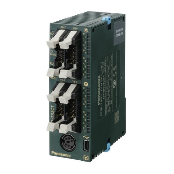
1.1 Unit Types 1.1.1 FP0R Control Units Specifications Progra Power Type No. of I/O Connecti Product No. supply Input Output port capacity points on type voltage Terminal ― AFP0RC10RS 10 points block 24V DC Relay output: (Input: 6 points/ steps ±common... - Page 17 Transistor output: (NPN) RS232C AFP0RT32CT 0.2A connector Transistor output: (PNP) RS232C AFP0RT32CP 32 points 0.2A (Input: 16 points/ 24V DC steps Output: 16 ±common Transistor points) output: (NPN) RS485 AFP0RT32MT 0.2A connector Transistor output: (PNP) RS485 AFP0RT32MP 0.2A Transistor output: (NPN) RS232C AFP0RF32CT 0.2A...
- Page 18 ±common Terminal 8 points AFP0RE8RS block Relay output: 24V DC (Input: 4 points, Molex ±common Output: 4 points) AFP0RE8RM connector FP0R-E8 Relay output: Terminal 8 points Expansion AFP0RE8YRS block (Output: 8 points) Unit Transistor 8 points output: (NPN) AFP0RE8YT connector (Output: 8 points) 0.3A...
- Page 19 Product Exclusive Product name Specifications supply Part No. manual voltage This is a link unit designed to make the FP0R FP0-IOL FP0 I/O Link Unit function as a slave unit to MEWNET-F (remote 24V DC AFP0732 This manual I/O system).
- Page 20 Suitable wire: AWG #26 / AWG AXW7231FP (5 pins in line) Σ FP0R/FP Power supply Attaches to FP0R control unit. Maintenance parts. Length: 1m AFPG805 (1-pack) cable FP0 Power supply cable Attaches to FP0 various units. Maintenance parts Length: 1m AFP0581(1-pack)
-
Page 21: Restrictions On Unit Combination
1.2 Restrictions on Unit Combination Up to three expansion units can be added on the right of the FP0R, these expansion units being either expansion units or intelligent units. A combination of relay output and transistor output types is also possible. -
Page 22: Programming Tools
The tool software can also be used with the FP series. "FPWIN GR Ver.2" or "FPWIN Pro Ver.6" Windows software is used with FP0R. FP Programmer cannot be used. 2.PC connection cable A commercial USB cable (A: mini B type) is used for the connection. - Page 23 Type of computer and suitable cable For the connection between a personal computer (RS232C) and the control unit (RS232C) D-sub connector cable PLC side PLC side connector Specifications Product No. connector Female-Mini DIN round 5-pin L type (3 m) AFC8503 D-sub 9-pin Female-Mini DIN round 5-pin Straight type (3 m)
- Page 24 1-10...
-
Page 25: Specifications And Functions Of Control Unit
Chapter 2 Specifications and Functions of Control Unit... -
Page 26: Part Names And Functions
2.1 Part Names and Functions 2.1.1 Part Names and Functions Operation monitor LEDs These LEDs display the current operation status of PLC such as RUN/STOP and ERROR/ALARM. LED and operation status Lights: In the RUN mode - The program is being executed. RUN (Green) Flashes: The forced input/output is being executed in the RUN mode. - Page 27 RUN/PROG. mode switch This switch is used to change the operation mode of PLC. Switch Operation mode RUN (Position: Up) RUN mode :The program is executed and the operation begins. PROG. (Position: Down) PROG. mode :The operation stops. In this mode, programming can be done using a tool software.
-
Page 28: Input And Output Specifications
2.2 Input and Output Specifications 2.2.1 Input Specifications Input specifications (for all types) Item Description Insulation method Optical coupler Rated input voltage 24 V DC operating voltage range 21.6 V DC to 26.4 V DC Rated input current Approx. 2.6 mA For C10: 6 points/common For C14, C16: 8 points/common Output points per common... - Page 29 2.2.2 Output Specifications Transistor output specifications Description Item Insulation method Optical coupler Output type Open collector Rated load voltage 5 V DC to 24 V DC 24 V DC Operating load voltage range 4.75 V DC to 26.4 V DC 21.6 V DC to 26.4 V DC Max.
- Page 30 Relay output specifications (C10/C14) Item Description Output type 1a output Note) Rated control capacity 2 A 250 V AC, 2 A 30 V DC (4.5 A or less/common) C10:2 points/common+1 point/common+1 point/common Output points per common C14:4 points/common+1 point/common+1 point/common OFF →...
-
Page 31: Terminal Layout Diagrams
2.3 Terminal layout diagrams Model No. Terminal layout diagrams C10RS C10CRS C10RM C10CRM (The above illustration is the terminal block type.) C14RS C14CRS C14RM C14CRM (The above illustration is the terminal block type.) - Page 32 Model No. Terminal layout diagrams C16T C16CT C16MT Note: Two COM terminals of the input circuit are connected internally. C16P C16CP C16MP Note: Two COM terminals of the input circuit are connected internally.
- Page 33 Model Terminal layout diagrams C32T C32CT C32MT T32CT T32MT F32CT F32MT Note: Four COM terminals of the input circuit are connected internally. Two (+) terminals of the output circuit are connected internally. Two (-) terminals of the output circuit are connected internally. C32P C32CP C32MP...
-
Page 34: Functions Of T32 Control Unit
2.4 Functions of T32 Control Unit 2.4.1 Memory Backup Function The FP0R-T32 control unit has a secondary battery (Charging type). The backup function for the operation memory and clock/calendar function can be used. Backup of operation memory (1) Timer/Counter (T/C) - Page 35 2.4.2 Built-in Backup Battery Time the built-in backup battery can be used (Backup time) The built-in backup battery is not charged when the unit is shipped. Charge the battery sufficiently before use. (Full charge (Ambient temperature: 25°C): 72 hours) It will be charged automatically if the DC power is supplied to the control unit. Relation between charging time and backup time The number of days in the backup time varies according to the rate of charging time.
- Page 36 2.4.3 Clock/Calendar The clock/calendar function is available for the FP0R-T32. Note) As the value is unstable in the initial state, write the value using a programming tool. Area of clock/calendar With the clock/calendar function, data indicating the hour, minute, second, day, year and other information stored in the special data registers DT90053 to DT90057 can be read using the transmission instruction and used in sequence programs.
- Page 37 Setting and changing using program (1) The values written to the special data registers DT90054 to DT90057, which are allocated as the clock/calendar setting area, are sent. (2) A value of H8000 is written to DT90058. Note) The value can be sent using the differential instruction "DF", or by changing H8000 to H0000. Example showing the date and time being written Set the time to 12:00:00 on the 5th day when the X0 turns on.
- Page 38 2-14...
-
Page 39: Expansion
Chapter 3 Expansion... -
Page 40: Expansion Method
The FP0/FP0R expansion units (expansion I/O unit, high-performance unit) are connected to the right side of the control Unit. Unit expansion is done using the right-side connector for FP0/FP0R expansion and the expansion hooks on the side of the unit. - Page 41 3.2 Part Names and Functions Expansion Units Part Names and Functions Power supply connector Supply 24 V DC. It is connected using the cable (AFP0581) supplied with the unit. Input connector Input indicator LED Output connector Output indicator LEDs Expansion hook This hook is used to secure expansion units.
- Page 42 Operating mode indicator LED display Note) The above table shows the specifications of FP0R Expansion Unit. For FP0 Expansion Unit, the rated input voltage is approx. 4.3 mA, and the input impedance is approx. 5.6 kΩ Limitations on number of simultaneous input on points Keep the number of input points per common which are simultaneously on within the following range as determined by the ambient temperature.
- Page 43 1 ms or less Response time ON→OFF 1 ms or less Surge absorber Zener diode Operating mode indicator LED display Note) The above table shows the specifications of FP0R expansion unit. For FP0 Expansion Unit, the maximum load current is 0.1 A.
- Page 44 Limitations on number of simultaneous input on points Keep the number of input points per common which are simultaneously on within the following range as determined by the ambient temperature. Internal circuit diagram [NPN] [PNP]...
-
Page 45: Terminal Layout Diagram
3.4 Terminal layout diagram Model No. Terminal layout diagrams E8RS E8RM E16RS E16RM E8YRS... - Page 46 Model Terminal layout diagrams E16T E8YT Note: Two COM terminals of the input circuit are connected internally. E16X E32T E16YT Note: Two COM terminals of the input circuit are connected internally. Two (+) terminals of the output circuit are connected internally. Two (-) terminals of the output circuit are connected internally.
- Page 47 Model Terminal layout diagrams E16P E8YP Note: Two COM terminals of the input circuit are connected internally. E32P E16YP Note: Two COM terminals of the input circuit are connected internally. Two (+) terminals of the output circuit are connected internally. Two (-) terminals of the output circuit are connected internally.
- Page 48 3-10...
-
Page 49: I/O Allocation
Chapter 4 I/O Allocation... - Page 50 Regarding I/O number Specifying X and Y numbers On the FP0R, the same numbers are used for input and output. Expression of numbers for input/output relays Since input relay "X" and output relay "Y" are handled in units of 16 points, they are expressed as a...
-
Page 51: I/O Allocation For Fp0R Control Unit
4.2 I/O Allocation for FP0R Control Unit 4.2.1 I/O Numbers of FP0R Control Unit The I/O allocation of FP0R control unit is fixed. Type of control unit Number of allocation I/O number Input (6 point) X0 to X5 Output (4 points) -
Page 52: I/O Numbers Of Fp0/Fp0R Expansion Unit
4.3 I/O Numbers of FP0/FP0R Expansion Unit - I/O numbers do not need to be set as I/O allocation is automatically performed when an expansion unit is added. - The I/O allocation of expansion unit is determined by the installation location. -
Page 53: Installation And Wiring
Chapter 5 Installation and Wiring... -
Page 54: Installation
5.1 Installation 5.1.1 Installation Environment and Space Operating environment (Use the unit within the range of the general specifications when installing) Ambient temperature: 0 to +55 °C Ambient humidity: 10 to 95 % RH (at 25 °C, non-condensing) For use in pollution Degree 2 environment. Do not use the unit in the following environments. - Page 55 Installation space Leave at least 50 mm of space between the wiring ducts of the unit and other devices to allow heat radiation and unit replacement. Maintain at least 100 mm of space between devices to avoid adverse affects from noise and heat when installing a device or panel door to the front of the PLC unit.
- Page 56 5.1.3 Installation Using the Optional Mounting Plate When using the slim type FP0 mounting plate (AFP0803) Use M4 size pan-head screws for attachment of the mounting plate and install according to the dimensions shown below. The rest of the procedure is the same as that for attaching the unit to the DIN rails. Note: When using an expansion unit, tighten the screws after joining all of the mounting plate to be connected.
- Page 57 An unit with an attached mounting plate can also be installed sideways on a DIN rail. Note: The flat type mounting plate (AFP0804) should be used only with the control unit as a stand-alone unit. It should not be used when the unit is being used in combination with an FP0/FP0R expansion unit.
-
Page 58: Wiring Of Power Supply
5.2 Wiring of Power Supply 5.2.1 Wiring of Power Supply Power supply wiring for the unit Use the power supply cable (Part number: AFPG805) that comes with the unit to connect the power supply. Brown: 24 V DC Blue: 0 V Green: Function earth Power supply wire To minimize adverse effects from noise, twist the brown and blue wires of the power supply cable. - Page 59 As for the FP0R control unit, since its power supply line is connected to the function earth through a high-voltage capacitor, it is no problem.
-
Page 60: Wiring Of Input And Output
5.3 Wiring of Input and Output 5.3.1 Input Wiring Connection of photoelectric sensor and proximity sensor Relay output type NPN open collector output type Voltage output type Two-wire output type Precaution when using LED-equipped reed switch When a LED is connected in series to an input contact such as LED-equipped reed switch, make sure that the voltage applied to the PLC input terminal is greater than the ON voltage. - Page 61 Precaution when using LED-equipped limit switch If the input of PLC does not turn off because of leakage current from the LED-equipped limit switch, the use of a bleeder resistor is recommended, as shown on the left.
- Page 62 5.3.2 Output Wiring Protective circuit for inductive loads With an inductive load, a protective circuit should be installed in parallel with the load. When switching DC inductive loads with relay output, be sure to connect a diode across the ends of the load.
-
Page 63: Wiring Of Mil Connector Type
5.4 Wiring of MIL Connector Type Supplied connector and suitable wires The connector listed below is supplied with the unit. Use the suitable wires given below. Also, use the required pressure connection tools for connecting the wires. Suitable wires (Twisted wire) Nominal cross-sectional Size Insulation thickness Remark... - Page 64 Wiring method The wire end can be directly crimped without removing the wire's insulation, saving labor. (1) Bend the welder (contact) back from the carrier, and set it in the pressure connection tool. (2) Insert the wire without removing its insulation until it stops, and lightly grip the tool. (3) After press-fitting the wire, insert it into the housing.
-
Page 65: Wiring Of Terminal Block Type
5.5 Wiring of Terminal Block Type Attached terminal block/Suitable wires A screw-down connection type is used for the terminal block. The suitable wires are given below. Terminal block socket The terminal socket manufactured by Phoenix Contact is used. Model No. of Phoenix Contact No. - Page 66 Wiring method (1) Remove a potion of the wire's insulation. (2)Insert the wire into the terminal block until it contacts the back of the block socket, and then tighten the screw clockwise to fix the wire in place. (The tightening torque: 0.22 to 0.25 N m (2.3 to 2.5 kgf-cm)) Notes for wiring When removing the wire's insulation, be careful not to scratch the core wire.
-
Page 67: Wiring Of Molex Connector Type
5.6 Wiring of Molex Connector Type Supplied connector and suitable wires The connector listed below is supplied with the unit. Use the suitable wires given below. Also, use the required pressure connection tools for connecting the wires. Supplied connector Manufacturer Molex Japan model No. -
Page 68: Wiring Of Com Port
5.7 Wiring of COM Port 5.7.1 Suitable Wires and Wiring Method Terminal block/Suitable wires A screw-down connection type is used for the COM port. Use the suitable wires given below. Terminal block The communication connector manufactured by Phoenix Contact is used. Phoenix Contact model No. - Page 69 Wiring method (1) Remove a potion of the wire's insulation. (2) Insert the wire into the COM port until it contacts the back side. (3) Tighten the screw. For tightening the terminal block When tightening the COM port, use a screwdriver (Phoenix Contact Co., Product No. 1205037) with a blade size of 0.4 x 2.5 (Part No.
- Page 70 5.7.2 Connection of COM Port (RS485 Type) Wiring should extend from one unit to the next, between "+" terminals, and "-" terminals as below. Never run two wires from a single unit to two other units. In the unit that serves as the terminal station, connect the "E" terminal and "-" terminal. 5.7.3 Selection of Transmission Cables (RS485 Type) Please use the following cables as transmission cables.
- Page 71 Set the baud rate before installation when using the COM port. System register settings For using the FP0R (RS485 type), set the baud rate of the COM port to 115200 bps or 19200 bps. The default setting of the system register is 9600 bps.
-
Page 72: Safety Measures
Operation of momentary power failures If the duration of the power failure is less than 5 ms, the FP0R continues to operate. If the power is off for 5 ms or longer, operation changes depending on the combination of units, the power supply voltage, and other factors. -
Page 73: Preparation Of Usb Port
Chapter 6 Preparation of USB Port... -
Page 74: Usb Connection
Windows® 2000 2.8 or later Windows® XP Windows Vista® FP-X, FP0R Windows® 7 2.9 or later Do not connect a computer to PLC with USB before installing FPWIN GR. When connecting a personal computer to PLC with USB, the dialog boxes as below may be displayed. - Page 75 Restrictions on USB Communication • The FP0R connected to the USB is recognized by the PC as that is connected through the COM port. When multiple FP0R units are connected to one PC with the USB, they cannot communicate with the PC simultaneously.
- Page 76 2. Select “Install from a list of specific location”, and click “Next>”. 3. Select “Search for the best driver in these locations”, and check “Include this location in the search”. Then, click the “Browse” button to specify the folder that the USB driver of FP0R has been stored, and click “Next>”.
- Page 77 5. Click “Finish” on the following screen to be displayed.
- Page 78 Procedure of installing the driver (e.g.: Windows® 7) 1. Once the FP0R is connected, the following screen is displayed. (It will automatically disappear after a short time.) 2. Click the start menu and move the mouse pointer to "Computer", and right-click on it to select "Properties".
- Page 79 4. Double-click on "FP0R". 5. Click "Update Driver...".
- Page 80 6. Click "Browse my computer for driver software". 7. Click the "Browse..." button to specify the folder that the USB driver of FP0R has been stored, and click "Next". If the location was not changed when installing FPWIN GR, the USB driver of FP0R has been stored in...
- Page 81 8. Although the following warning dialog box appears, click "Install this driver software anyway". 9. The installation of the driver software begins. Once the installation completes successfully, the following screen will be displayed. In this case, the USB port has been assigned to "COM4". However, it may differ depending on the environment of the PC you use.
- Page 82 6.1.3 Confirming COM Ports The USB connected to the FP0R is recognized as a COM port by a PC. The COM port number assigned to the USB differs according to the PC environment. How to confirm COM port 1. Connect the PLC and a PC with a USB cable.
- Page 83 6.1.4 Communication with Programming Tool The following communication setting should be specified to perform the communication with a programming tool (FPWIN GR/FPWIN Pro) using the USB. 1. Display the "Communication Setting" window from the programming tool. <Using FPWIN GR> Select "Communication Setting" under "Option" from the menu bar. <Using FPWIN Pro>...
- Page 84 6-12...
-
Page 85: Communication
Chapter 7 Communication... -
Page 86: Functions And Types
Reading and writing of data is done using a ladder program in the FP0R, while reading and writing of data from an external is handled through the data registers. - Page 87 7.1.5 MODBUS RTU Function overview The MODBUS RTU protocol enables the communication between the FP0R and other devices (including our FP-e, Programmable display GT series and KT temperature control unit). Communication is performed when the master unit sends instructions (command messages) to slave units and the slave unit returns responses (response messages) according to the instructions.
-
Page 88: Communicaton Port Type
7.2 Communicaton Port Type 7.2.1 Tool Port This connector is used to connect a programming tool. A commercial mini-DIN 5-pin connector is used for the tool port on the control unit. Pin No. Signal name Abbreviation Signal direction Signal Ground Send Data Unit →... -
Page 89: Communication Specifications
7.3 Communication Specifications Tool Port Description Interface RS232C Transmission distance 15 m Baud rate 2400,4800,9600,19200,38400,57600,115200 bit/s Communication method Half-duplex communication Synchronous method Start stop synchronous system Data length: 7 bits/8bits Parity: None/Even/Odd Communication format Start code: STX/No STX End code: CR/CR+LF/None/ETX Stop bit: 1 bit/2 bits Data transmission order Transmits from bit 0 character by character. - Page 90 COM port (RS485) Item Description Interface RS485 Communication mode 1:N communication Note1) 2) Transmission distance Max. 1200 m Note2) 3) Baud rate 19200, 115200 bps Communication method Two-wire, half-duplex transmission Synchronous method Start stop synchronous system Transmission line Shielded twisted-pair cable or VCTF Computer link ASCII Transmission...
-
Page 91: Computer Link
It is necessary to set the system register of the communication port to the computer link for using this function. Both the master and slave functions are available for the FP0R, however, only the slave function is available for the tool and USB ports. - Page 92 7.4.2 MEWTOCOL Slave Function Outline of operation Command and response Instructions issued by the computer to the PLC are called commands. Messages sent back to the computer from the PLC are called responses. When the PLC receives a command, it processes the command regardless of the sequence program, and sends a response back to the computer.
- Page 93 Key Point: With the FP0R, an expansion header "<" is supported to send single frame of up to 2048 characters as well as general "%". Type of header No.
- Page 94 Response message The PLC that received the command in the example above sends the processing results to the computer. 1. Header (Start code) A "%" (ASCII code: H25) or a "<" (ASCII code: H3C) must be at the beginning of a message. The response must start with the same header that was at the beginning of the command.
- Page 95 Commands to be used Command name Code Description Reads the on and off status of contacts. (RCS) -Specifies only one point. Read contact area (RCP) -Specifies multiple contacts. (RCC) -Specifies a range in word units. Turns contacts on or off. (WCS) -Specifies only one point.
- Page 96 7.4.3 Setting Communication Parameters Tool port/COM port The settings for baud rate and communication format are entered using a programming tool. Note: When the MEWTOCOL master is used, also select "Computer Link". (COM port only) Setting with FPWIN GR Select "Options" in the menu bar, and then select "PLC Configuration". Click "Tool Port" or "COM Port" from the left list.
- Page 97 7.4.4 1:1 Communication (MEWTOCOL Slave Function) Overview For a 1:1 computer link between the FP0R and a computer, and RS232C cable is needed. Communication is performed via commands from the computer and responses from the PLC. System register settings Name Set value No.410...
- Page 98 7.4.5 1:N Communication (MEWTOCOL Slave Function) A computer and PLCs are connected through a commercially available RS232C-RS485 converter, and the respective computer and PLCs are wired using an RS485 cable with crossover wiring. The computer and the PLC communicate via commands and responses: The computer sends a command specifying the unit number, and the PLC with that unit number sends a response back to the computer.
- Page 99 7.4.6 MEWTOCOL Master Use the F145 (SEND) "Data send" or F146 (RECV) "Data receive" instruction to use the MEWTOCOL master function. Communication port The MEWTOCOL master is not available for the tool port. It is available for the COM port only. Sample program 7-15...
- Page 100 Flowchart With the above program, the procedures 1 to 3 are executed repeatedly. 1. Updates the write data if the write data (DT50 and DT51) and the read data (DT60 and DT61) are matched. 2. Writes the DT50 and DT51 of the local unit into the data DT0 and DT1 in the unit number 1 from the COM port.
- Page 101 Setting Communication Parameters Confirm that the model of the programming tool is FP0. Note) Only the salve function is available in the FP0 compatibility mode. Usable communication ports on FP0R (FP0 compatibility mode) Tool port USB port (No communication parameter)
-
Page 102: General-Purpose Serial Communication
Data is read from and written to an external device connected to the communication port by means of an FP0R program and the FP0R data registers. Outline of operation To send data to and receive it from an external device using the general-purpose serial communication function, the data transmission and data reception functions described below are used. - Page 103 7.5.2 Programming Example of General-purpose Serial Communication The F159(MTRN) instruction is used to send and receive data via the specified communication port. F159 (MTRN) instruction Data is sent and received via the specified COM port . Devices that can be specified for S: Only data registers (DT) can be specified as the send buffer.
- Page 104 Data to be sent/received with FP0R Remember the following when accessing data in the FP0R send and receive buffers: If a header has been chosen in the communication format settings, the code STX (H02) will automatically be added at the beginning of the data begin sent.
- Page 105 7.5.3 Sending Data Communication with external devices is handled through the data registers. Data to be output is stored in the data register used as the send buffer (DT), and when the F159 (MTRN) instruction is executed, the data is output from the communication port. Data table for transmission (send buffer) Sample program for sending data The following program transmits the characters “ABCDEFGH (Hex)”...
- Page 106 Explanation of data table The data table for transmission starts at the data register specified in S. Use an F0 (MV) or F95 (ASC) instruction to write the data to be transmitted to the transmission data storage area specified in S. Transmission process When the execution condition of the F159 (MTRN) instruction turns on and the “transmission done”...
- Page 107 7.5.4 Receiving Data Data input from the communication port is stored in the receive buffer specified by the system register, and the “reception done” flag goes on. If the “reception done” flag is off, data can be received at any time. Data table for reception (receive buffer) This is the state when the above program is executed.
- Page 108 Explanation of data table Data sent from an external device connected to the communication port is stored in the data registers that have been set as the receive buffer. Specify the data registers in system register 416 to 419. The number of bytes of data received is stored in the starting address of the receive buffer.
- Page 109 7.5.5 Flag Operation in Serial Communication Header: No-STX, Terminator: CR Receiving data: The “reception done” flag, the “transmission done” flag, and the F159 (MTRN) instruction are related as follows: For general-purpose serial communication, half-duplex transmission must be used. Reception is disabled when the “reception done” flag R9038 is on. When F159 (MTRN) is executed, the number of bytes received is cleared, and the address (write pointer) in the receive buffer is reset to the initial address.
- Page 110 Header: STX, Terminator: ETX Receiving data: The “reception done” flag, the “transmission done” flag, and the F159 (MTRN) instruction are related as follows: The data is stored in the receive buffer in sequential order. When the header is received, the number of bytes received is cleared, and the address (write pointer) in the receive buffer is reset to the initial address.
- Page 111 Sending data: The “reception done” flag, the “transmission done” flag, and the F159 (MTRN) instruction are related as follows: Header (STX) and terminator (ETX) are automatically added to the data being transmitted. The data is transmitted to an external device. When the F159 (MTRN) instruction is executed, the “transmission done”...
- Page 112 7.5.6 Changing Communication Mode Using F159(MTRN) Instruction An F159 (MTRN) instruction can be executed to change between general-purpose serial communication mode and computer link mode. To do so, specify H8000 for n (the number of transmission bytes) and execute the instruction. Changing from “general-purpose”...
- Page 113 7.5.7 Setting Communication Parameters Tool port/COM port The settings for baud rate and communication format of the tool port are entered using a programming tool. Setting with FPWIN GR Select "Options" in the menu bar, and then select "PLC Configuration". Click "Tool Port" or "COM Port" from the left list.
- Page 114 7.5.8 Connection with 1:1 Communication (General-purpose Serial Communication) System register settings Name Set Value No. 412 Selection of communication mode General-purpose serial communication No. 413 Communication format Char. bit: …… 7 bits/8 bits Parity: ….. None/Odd/Even Stop bit: ………… 1 bit/2 bits Terminator: ……..
- Page 115 7.5.9 1:N Communication (General-purpose Serial Communication) The FP0R and the external units are connected using an RS485 cable. Using the protocol that matches the external units, the F159 (MTRN) instruction is used to send and receive data. System register settings...
- Page 116 F159(MTRN) instruction. F144(TRNS) instruction Data is sent and received between the FP0R and an external device via the COM port (RS232C port). Devices that can be specified for S: Only data registers (DT) can be specified as the send buffer.
- Page 117 Setting Communication Parameters Confirm that the model of the programming tool is FP0. Usable communication port COM port (RS232C port) COM port (RS232C port) settings Dialog box of PLC system register setting No. 412 Communication mode Select "General communication". No. 413 Communication Format setting Char.
-
Page 118: Pc(Plc) Link Function
7.6 PC(PLC) link Function 7.6.1 Overview A system can be configured for the PC(PLC) link (MEWNET-W0) with the FP0R. Exclusive internal relays "link relays (L)" and data registers "link registers (LD)" are shared between the connected PLCs. Turning on a link relay contact in one PLC turns on the same link relay in all other PLCs on the same network. - Page 119 Operation of PLC link Turning on a link relay contact in one PLC turns on the same link relay in all other PLCs on the same network. Likewise, if the contents of a link register in one PLC are changed, the values of the same link register are changed in all PLCs on the same network.
- Page 120 7.6.2 Setting of Unit Numbers By default, the unit number for the communication port is set to 1 in the system registers. In a PC(PLC) link that connects multiple PLCs on the same transmission line, the unit number must be set in order to identify the different PLCs.
- Page 121 7.6.3 Setting Communication Parameters: PC(PLC) Link Settings for baud rate and communication format The settings for baud rate and communication format of the COM port are entered using a programming tool. Setting with FPWIN GR Select "Options" in the menu bar, and then select "PLC Configuration". Click the "COM Port" tab. Dialog box of PLC system register setting No.
- Page 122 7.6.4 Link Area Allocation The link relays and link registers to be used in the PC(PLC) link are allocated in the link area of the CPU unit. Link area allocations are specified by setting the system registers of the CPU unit. System registers Default Name...
- Page 123 Example of allocation The areas for PC(PLC) link are divided into send areas and receive areas. The link relays and link registers are sent from the send area to the receive area of a different PLC. Link relays and link registers with the same numbers as those on the transmission side must exist in the receive area on the receiving side.
- Page 124 For PC(PLC) link 1 Link relay allocation System registers Setting for various units Name No. 1 No. 2 No. 3 No. 4 Range of link relays used Starting No. of word for link relay transmission Link relay transmission size Note) No.50 (range of link relays used) must be set to the same range for all the units. Link register allocation System registers Setting for various units...
- Page 125 Partial use of link areas In the link areas available for PC(PLC) link, link relays with a total of 1024 points (64 words) and link registers with a total of 128 words can be used. This does not mean, however, that it is necessary to reserve the entire area.
- Page 126 Note: Precautions When Allocating Link Areas If a mistake is made when allocating a link area, be aware that an error will result, and communication will be disabled. Avoid overlapping send areas When sending data from a send area to the receive area of another PLC, there must be a link relay and link register with the same number in the receive area on the receiving side.
- Page 127 7.6.5 Setting the Largest Unit Number for PC(PLC) Link The largest unit number can be set using system register no.47 (using system register no.57 for PC(PLC) link 1). [Sample setting] No. of units linked Setting contents 1st unit: Unit no. 1 is set 2nd unit: Unit no.
- Page 128 7.6.6 Monitoring When using a PC(PLC) link, the operation status of the links can be monitored using the following relays. Transmission assurance relays For PC(PLC) link 0: R9060 to R906F (correspond to unit no. 1 to 16) For PC(PLC) link 1: R9080 to R908F (correspond to unit no. 1 to 16) If the transmission data from a different unit is being used with the various PLCs, check to make sure the transmission assurance relay for the target unit is on before using the data.
- Page 129 7.6.7 PC(PLC) Link Response Time The maximum value for the transmission time (T) of one cycle can be calculated using the following formula. The various items in the formula are calculated as described below. Ts (transmission time per station) ○ Ts = scan time + Tpc (PC(PLC) link sending time) Tpc = Ttx (sending time per byte) x Pcm (PLC link sending size) Ttx = 1/(baud rate x 1000) x 11 ms ….
- Page 130 Calculation example 3 When all but one station have been added to a 16-unit link, the largest station number is 16, relays and registers have been allocated evenly, and the scan time for each PLC is 5 ms. Ttx = 0.096 Each Ts = 5 + 6.82 = 11.82 ms Tlt = 0.096 x (13 + 2 x 15) ≒...
- Page 131 Reducing the transmission cycle time when there are stations that have not been added If there are stations that have not been added to the link, the Tlk time (link addition processing time) and with this the transmission cycle time will be longer. With the SYS1 instruction, the link addition waiting time Twt in the above formula can be reduced.
- Page 132 Error detection time for transmission assurance relays The power supply of any given PLC fails or is turned off, it takes (as a default value) 6.4 seconds for the transmission assurance relay of the PLC to be turned off at the other stations. This time period can be shortened using the SYS1 instruction.
-
Page 133: Modbus Rtu Communication
The MODBUS RTU communication is a function for the master unit to read and write the data in slave units communicating between them. There are ASCII mode and RTU (binary) mode in the MODBUS protocol, however, the FP0R is supported with the RTU (binary) mode only. - Page 134 MODBUS RTU command message frame START ADDRESS FUNCTION DATA CRC CHECK 3.5-character time 8 bits 8 bits n*8 bits 16 bits 3.5-character time ADDRESS (Unit No.) 8 bits, 0 to 99 (decimal) Note1) 0= Broadcast address Note2) Slave unit No. is 1 to 99 (decimal) Note3) For MODBUS, 0 to 247 (decimal) FUNCTION 8 bits...
- Page 135 Words Cannot be issued Mask Write 4X Register Write DT Mask Cannot be issued Read/Write 4X Registers Read/Write DT Table for MODBUS reference No. and FP0R device No. Data on BUS MODBUS reference No. PLC device No. (hexadecimal) 000001-001760 0000-06DF...
- Page 136 7.7.2 Setting Communication Parameters Settings for baud rate and communication format The settings for baud rate and communication format of the COM port are entered using a programming tool. Setting with FPWIN GR Select "Options" in the menu bar, and then select "PLC Configuration". Click the "COM Port" tab. Dialog box of PLC system register setting No.
- Page 137 7.7.3 MODBUS Master Use the F145 (SEND) “Data send” or F146 (RECV) “Data receive” instruction to use the MODBUS master function. Sample program 7-53...
- Page 138 Flow chart The above program executes the operation 1 to 3 repeatedly. 1. Updates the write data if the write data (DT50 and DT51) and the read data (DT60 and DT61) are matched. 2. Writes the DT50 and DT51 of the local unit into the data DT0 and DT1 in the unit number 1 from the COM port.
- Page 139 Sample program (For Type II) Use a program as below to directly specify a MODBUS address. 7-55...
- Page 140 Flow chart (For Type II) The above program executes the operation 1 to 3 repeatedly. 1. Updates the write data if the write data (DT50 and DT51) and the read data (DT60 and DT61) are matched. 2. Writes the DT50 and DT51 of the local unit into the data No. H7788 in the unit number 07 from the COM port.
-
Page 141: Functions
Chapter 8 High-speed Counter, Pulse Output and PWM Output Functions... -
Page 143: Overview Of Each Functions
8.1 Overview of Each Functions 8.1.1 Three Pulse Input/Output Functions High-speed counter function The high-speed counter function counts external inputs such as those from sensors or encoders. When the count reaches the target value, this function turns on/off the desired output. Pulse output function Combined with a commercially available motor driver, the function enables positioning control. - Page 144 8.1.2 Performance of Built-in High-speed Counter Number of Channel • There are six channels for the built-in high-speed counter • The channel number allocated for the high-speed counter will change depending on the function being used. Counting range • K-2, 147, 483, 648 to K+2, 147, 483, 647 (Coded 32-bit binary) •...
-
Page 145: Function Specifications And Restricted Items
8.2 Function Specifications and Restricted Items 8.2.1 Specifications High-speed counter function Input/output Performance contact No. being Memory area being used specifications used High-speed counter Input contact channel No. Mini-mum Maximum number (value in Control Elapsed Target input pulse counting parenthesis is flag value area value area... - Page 146 Pulse output function Input/output contact number Memory area used used Deviation Position Pulse High-speed counter counter clear Near Target Home control output Elapsed channel No. output home Target area for pulse sign input starting instruct value input value area match Note3) out- out-...
- Page 147 8.2.2 Functions Used and Restrictions Simplified chart - Maximum counting speed of High-speed counter The maximum counting speed of the high-speed counter varies according to No. of channels to be used or the simultaneous use of the pulse output function. Use the chart below as a guide. Max.
- Page 148 Max. counting speed (Frequency kHz) Combination with pulse output function (Trapezoidal control, No change in speed 50kHz) Pulse output 2 CH Pulse output 3 CH Pulse output 4 CH Single- Single- Single- 2-phase 2-phase 2-phase phase phase phase Note) The maximum counting speed may be lower than the above-mentioned values when the change of pulse output speed, CAM control instruction, target value match ON/OFF instruction and other interrupt programs are executed simultaneously.
- Page 149 FP0R pulse output performance Independent control Single-phase Maximum output frequency kHz Available Available Available Available Available Available Available Available Available Available Note) Even if all channels are used, they can be used within the ranges above. Interpolation control Linear interpolation...
-
Page 150: High-Speed Counter Function
8.3 High-speed Counter Function 8.3.1 Overview of High-speed Counter Function Instructions used and the contents of the controls Type of control Instruction Description number Reset/disabling of Performs controls such as resetting the high-speed counter of counter the specified channel or disabling the count. Read/Write of Reads and writes the elapsed value of the high-speed counter. - Page 151 Count for reset input (Incremental input mode) The reset input is executed by the interruption at (1) on (edge) and (2) off (edge). (1) on (edge) … Count disable, Elapsed value clear (2) off (edge) … Count enable DT90052 (bit2): “able/disable” setting of the input can be set by the reset input.
- Page 152 8.3.4 I/O Allocation • As shown in the table in the previous section “8.2.1”, the inputs and outputs used will differ depending on the channel number being used. • The output turned on and off can be specified from Y0 to Y7 as desired with instructions F166 (HC1S) and F167 (HC1R).
- Page 153 High-speed counter/pulse output control flag area of FP0R • The area DT90052 for writing channels and control codes is allocated as shown in the left figure. • Control codes written with an F0 (MV) instruction are stored by channel in special data registers DT90370 to DT90375.
- Page 154 Elapsed value write and read instruction (F1) • This instruction writes or reads the elapsed value of the high-speed counter. • Specify this instruction together with the elapsed value area of high-speed counter after the special data register DT90300. • If the F1 (DMV) instruction is executed specifying DT90300, the elapsed value will be stored as 32-bit data in the combined area of special data registers DT90300 and DT90301.
- Page 155 Input pulse measurement instruction (F178) This instruction is used to measure the pulse number and cycle of a specified high-speed counter channel when using the high-speed counter function. The pulse number to be measured is counted in a specified counting cycle. The one pulse (on-off cycle) right after the execution of the instruction is measured as the pulse cycle.
- Page 156 Sample program (F178) 8.3.6 High-speed counter control flag Note that there are the following restrictions on using each function of the high-speed counter. Allocation and role of high-speed counter control flag When a high-speed counter instructions (F165/F166/F167/F178) is executed, the high-speed counter control flag of the corresponding channel is ON.
- Page 157 8.3.7 Sample program Positioning operations with a single speed inverter Wiring example Operation chart I/O allocation I/O No. Description Encoder input Operation start signal Inverter operation signal R100 Positioning operation running R101 Positioning operation start R102 Positioning done pulse R9110 High-speed counter CH0 control flag Program When X5 is turned on, Y0 turns on and the conveyor begins moving.
- Page 158 Positioning operations with a double speed inverter Wiring example Operation chart I/O allocation I/O No. Description Encoder input Operation start signal Inverter operation signal Inverter high-speed signal R100 Positioning operation running R101 Positioning operation start R102 Arrival at deceleration point R103 Positioning done pulse R900C...
- Page 159 Program When X5 is turned on, Y0 and Y1 turn on and the conveyor begins moving. When the elapsed value (DT90300 and DT90301) reaches K4500, Y1 turns off and the conveyor begins decelerating. When the elapsed value reaches K5000, Y0 turns off and the conveyor stops. 8-19...
-
Page 160: Pulse Output Function
8.4 Pulse Output Function 8.4.1 Overview of Pulse Output Function Instructions used and the contents of the controls Type of control Instruction Description number Forced stop, Controls to stop a specified channel. deceleration stop Read/Write of Reads and writes the elapsed value of the built-in high-speed elapsed value counter during the pulse output control. - Page 161 8.4.2 Types of Pulse Output Method and Operation Modes Clockwise/counter-clockwise output method Control is carried out using two pulses: a forward rotation pulse and a reverse rotation pulse. Pulse/direction output method (forward: OFF/reverse: ON) Control is carried out using one pulse output to specify the speed and another to specify the direction of rotation with on/off signals.
- Page 162 Operation mode Incremental <Relative value control> Outputs the pulses set with the target value. Selected Pulse and direction Pulse and direction Mode HSC counting CW/CCW forward OFF/ forward ON/ Target Method reverse ON reverse OFF value Pulse output when Pulse output when Pulse output Positive direction output is...
- Page 163 8.4.3 I/O Allocation Double pulse input driver (CW pulse input and CCW pulse input method) • Two output contacts are used as a pulse output for “CW, CCW”. • The I/O allocation of pulse output terminal and home input is determined by the channel used. •...
- Page 164 Wiring example Note) When the stepping motor input is a 5 V optical coupler type, connect a resister of 2 kΩ (1/2 W) to R1, and connect a resistor of 2 kΩ (1/2 W) − 470 Ω (2 W) to R2. Table of I/O allocation I/O No.
- Page 165 8.4.4 Pulse output control instructions (F0) (F1) Pulse output control instruction (F0) • This instruction is used for resetting the built-in high-speed counter, stopping the pulse output, and setting and resetting the near home input. • Specify this F0 (MV) instruction together with special data register DT90052. •...
- Page 166 FP0R Pulse output control flag area • The area DT90052 for writing channels and control codes is allocated as shown in the left figure. • Control codes written with an F0 (MV) instruction are stored by channel in special data register DT90380 to DT90383.
- Page 167 8.4.5 Forced Stop, Deceleration Stop (F0) Instruction Pulse output control instruction (F0) Forced stop and deceleration stop is executed by F0(MV) instruction in combination with the special data register DT90052. Once this instruction is executed, the settings will remain until this instruction is executed again.
- Page 168 8.4.6 Elapsed Value Read and Write (F1) Instruction Elapsed value read and write instruction (F1) This instruction is used to read and write the pulse number counted by the pulse output control. Specify this F1 (DMV) instruction in combination with the pulse output elapsed area after the special data register DT90400.
- Page 169 8.4.7 JOG Operation Instruction (F172) This instruction is used to output pulses according to a specified parameter when the trigger (execution condition) is on. When the trigger (execution condition) turns off, deceleration is performed within a specified deceleration time. However, if the trigger turns on again, acceleration is performed up to the target speed again.
- Page 170 Sample program JOG operation: Type 0 (No target value) The explanation below shows the case that pulses are output from Y0 when using forward rotation and Y1 when using reverse rotation with the following conditions; Initial speed: 1 kHz, Target speed: 7kHz, Acceleration time: 100 ms, Deceleration time: 1000 ms.
- Page 171 Sample program Control code Precautions during programming For using the pulse output function, it is necessary to set the system register No. 402. Performing rewriting during RUN stops the pulse output. 8-31...
- Page 172 Sample program JOG operation: Type 1 (With target value) The explanation below shows the case that pulses are output from Y0 when using forward rotation and Y1 when using reverse rotation with the following conditions; Initial speed: 1 kHz, Target speed: 5kHz, Acceleration time: 120 ms, Deceleration time: 120 ms.
- Page 173 Sample program Control code Precautions during programming For using the pulse output function, it is necessary to set the system register No. 402. Performing rewriting during RUN stops the pulse output. 8-33...
- Page 174 8.4.8 Home Return Instruction (F177) When the trigger (execution condition) turns on, the home return is performed according to a specified data table. On the completion of the home return, the elapsed value area is reset to "0". Operation modes of Home return operation There are two kinds of operation modes, which are type 0 and type 1.
- Page 175 Sample program: Home return The explanation below shows the case that home return is performed with the following conditions; Initial speed: 1 kHz, Target speed: 5 kHz, Creep speed: 500 Hz, Acceleration time: 300 ms, Deceleration time: 500 ms. Timing chart Data table Data register...
- Page 176 Sample program Control code Precautions during programming For using the pulse output function, it is necessary to set the system register No. 402. When the deceleration stop is requested by the F0 instruction during the pulse output, the deceleration stop is performed. Even when the home input is on, the pulse output starts by the execution of this instruction.
- Page 177 8.4.9 Trapezoidal Control Instruction (F171) This instruction automatically performs trapezoidal control according to the specified data table while the trigger (execution condition) is on. Control method of Trapezoidal control instruction (F171): Type 0 and Type 1 There are two kinds of operation modes, which are type 0 and type 1. Type 0 For type 0, the time from the initial speed to the target speed is specified as acceleration time or deceleration time.
- Page 178 Sample program: Trapezoidal control Type 0 (F171) The explanation below shows the case that pulses are output from Y0 with the following conditions; Initial speed: 1 kHz, Target speed: 10 kHz, Acceleration time: 100 ms, Deceleration time: 1000 ms, Movement amount: 30000 pulses. Timing chart Data table Data...
- Page 179 Sample program Control code Precautions during programming For using the pulse output function, it is necessary to set the system register No. 402. Performing rewriting during RUN stops the pulse output. When the deceleration stop is requested by the F0 instruction during the pulse output, the deceleration stop is performed.
- Page 180 8.4.10 Speed Change After Starting Trapezoidal Control Type 0 (F171) The explanation below shows the program to change the speed to a speed below the target speed during the trapezoidal control. Use the type 0 to change the speed to a speed slower than the target speed. Time chart Sample program Precautions during programming...
- Page 181 8.4.11 Speed Change After Starting Trapezoidal Control Type 1 (F171) The explanation below shows the program to change the speed to a speed over the target speed during the trapezoidal control. Use the type 1 to change the speed to a speed faster than the target speed. Time chart Sample program Precautions during programming...
- Page 182 8.4.12 Precautions When Changing Speed (Common to F171 and F172) Precautions during programming To change the speed, specify the execution condition of instruction to be always executed. Using the type 0 of trapezoidal control instruction (F171) enables to perform the acceleration/deceleration control up to the target value.
- Page 183 8.4.13 JOG Positioning Control Instruction (F171) When the trigger (execution condition) turns on, the JOG operation is started. When the position control start input becomes effective, a specified pulse is output and the deceleration stop is performed. The position control start input becomes effective when the leading edge of the external inputs X0 to X3 or the bit 6 of the special data register DT90052 is detected.
- Page 184 Note: When the position control start input does not turn on, the pulse output will not stop. Create a program to stop the operation when an error occurs, with a combination of the forced stop by the F0 instruction (bit 3 of DT90052) and the deceleration stop by the F0 instruction (bit 5 of DT90052). As for the position control start input, only the leading edge is detected.
- Page 185 Sample program: JOG positioning operation: Type 0 When the trigger (execution condition) is on, the JOG operation is started. When the position control start input turns on, a specified pulse is output and the deceleration stop is performed. Time chart Data table Data Setting item (Unit)
- Page 186 Sample program Control code Only when the target value is set to "0", the pulse output direction can be reversed by changing the output type assignment from "0,1,2" to "4,5,6". Precautions during programming For using the pulse output function, it is necessary to set the system register No. 402. When the instruction is started during the interrupt program, specify the execution in the interrupt program with the control code.
- Page 187 Sample program: JOG positioning operation: Type 1 When the trigger (execution condition) is on, the JOG operation is started. When the position control start input turns on, the position control is performed up to a specified target value after changing the target speed at the changeover time specified in advance.
- Page 188 Sample program Control code Precautions during programming For using the pulse output function, it is necessary to set the system register No. 402. When the instruction is started during the interrupt program, specify the execution in the interrupt program with the control code. When describing the same channel in both the normal program and the interrupt program, be sure to program not to execute them simultaneously.
- Page 189 8.4.14 JOG Positioning Control Type 0 - Change Speed (F171) Use the type 1 to change the speed to a speed faster than the target speed. Time chart Sample program Precautions during programming To change the speed, specify the execution condition of F171 instruction to be always executed. Using the type 1 enables to perform the acceleration/deceleration control up to the maximum speed (50 kHz).
- Page 190 8.4.15 Data Table Control Instruction (F174) Pulses are output from the specified channel according to the specified data table. Positioning is performed sequentially according to the values of data tables, and stops at the data table that the value of pulse output stop (K0) is written. Time chart Data table Data...
- Page 191 Sample program Control code Precautions during programming When the deceleration stop is requested by the F0 instruction during the pulse output, an operation similar to the forced stop is performed and the pulse output stops immediately. 8-51...
- Page 192 8.4.16 Linear Interpolation Control Instruction (F175) The linear interpolation controls positioning with two axes according to the specified data table. Specify the number (K0 or K2) corresponding to the channel (CH0 or CH2) assigned to the X axis to execute the F175 instruction. Time chart Data table Data...
- Page 193 Sample program Control code Precautions during programming For using the pulse output function, it is necessary to set the system register No. 402. Specify the composite speed to make the component speed of each axis be 6 Hz or more. Set the composite speed (Initial speed) to be 30 Hz or less.
- Page 194 8.4.17 Difference in Acceleration/Deceleration Characteristics Between Instructions The method to calculate the acceleration/deceleration time and the speed table for acceleration/deceleration differs according to the type of pulse output instructions. Select an appropriate type of instruction according to applications. Acceleration/deceleration characteristics of each instruction Common to JOG operation Type 0 and Type 1 (F172) Specify the time from the initial speed to the maximum speed (50 kHz) as acceleration time and the time from the maximum speed (50 kHz) to the initial speed as deceleration time in the program.
- Page 195 Trapezoidal control Type 0 (F171) Specify the time from the initial speed to the target speed as acceleration time and the time from the target speed to the initial speed as deceleration time in the program. Each section between the initial speed and the target speed, and between the target speed and the initial speed is divided into the speed table of 30 steps to calculate the speed.
- Page 196 JOG positioning control Type 0 (F171) Specify the time from the initial speed to the maximum speed (50 kHz) as acceleration time and the time from the maximum speed (50 kHz) to the initial speed as deceleration time in the program. The actual acceleration/deceleration time is relatively shorter than the specified acceleration/deceleration time.
- Page 197 8.4.18 Pulse Output Instruction Flag Note that there are the following restrictions on using each function of the pulse output Allocation and role of pulse output instruction flag When a pulse output instruction (F171/F172/F174/F175/F177) or PWM output instruction (F173) is executed and pulses are being output, the pulse output instruction flag of the corresponding channel is ON.
-
Page 198: Pwm Output Function
8.5 PWM Output Function 8.5.1 Overview PWM output function With the F173 (PWMH) instruction, the pulse width modulation output of the specified duty ratio is obtained. System register setting In order to use the PWM output function, it is necessary to set system register numbers no.402. 8.5.2 PWM Output Instruction F173 While X6 is on, a pulse with a period of 1 ms and duty ratio of 50% is output from Y0 of specified channel... -
Page 199: Security Functions
Chapter 9 Security Functions... -
Page 200: Password Protect Function
9.1.1 Password Protect Function This function is used to prohibit reading and writing programs and system registers by setting a password on the FP0R. There are two ways to set a password as below. 1. Sets using the programming tool. - Page 201 If you fail to input the correct password for 3 times in succession, you cannot access the program. Turn the power supply of the FP0R off and then on again to try to input the password again. Note: If the power supply of the PLC is turned on/off with the setting that the access is allowed, the setting will...
- Page 202 How to prohibit access with password 1. Select "Tool" > "Set PLC Password" in the menu bar. The "Set PLC Password" dialog box is displayed. 2. Set the items in the table below, and click on the “Settings” button. Item Settings Digit number Select “4 digits”...
- Page 203 How to permit access with password 1. Select "Tool" > "Set PLC Password" in the menu bar. The "Set PLC Password" dialog box is displayed. Set the items in the table below, and click on the “Settings” button. Item Settings Digit number Select “4 digits”...
- Page 204 How to cancel the password protection Following two methods are available to cancel the password setting. Description Program Unprotect Cancels the registered password to be specified. All programs are retained. All programs are deleted. Erases all programs and security information to Force cancel (The upload protection cancel the setting forcibly.
- Page 205 How to force cancel (Programs and security information are all deleted.) 1. Select "Tool" > "Set PLC Password" in the menu bar. The "Set PLC Password" dialog box is displayed. 2. Click the "Force Cancel" button. A confirmation message is displayed. 3.
-
Page 206: Upload Protection
9.2 Upload Protection 9.2.1 Upload Protection Overview of program upload protection function This function is to prohibit reading programs and system registers by setting to disable program uploading. If the upload protection is set, note that the ladder programs and system registers will be disabled to be uploaded after that. -
Page 207: Setting Function For Fp Memory Loader
9.3.1 Setting Function for FP Memory Loader The following two functions of the FP memory loader (AFP8670/AFP8671) (*) can be set through the FP0R. Limited distribution function (Programs can be downloaded only to the units which the same password has been set.) When downloading a program from the memory loader, the program can be downloaded only when the program stored in the memory loader matches the password set for the PLC with this function enabled. - Page 208 9.3.2 Setting Method Setting with FPWIN GR 1. Select "Online" > "Online Edit Mode" in the menu bar, and press the CTRL and F2 keys. The screen is switched to "Online Monitor". 2. Select "Tool" > "Set PLC Password" in the menu bar. The "Set PLC Password"...
- Page 209 Note2) Although programs cannot be downloaded with FP memory loader Ver.2 or later, only the upload protection setting is activated. Status of PLC that program has been downloaded Status of FP memory loader Password setting for FP0R after download No password setting The password will be cleared. 4-digit password setting The password will be overwritten with a new 4-digit password.
-
Page 210: Table Of Security Settings/Cancel
9.4 Table of Security Settings/Cancel For the settings on the FP0R control unit Status of security Security not Upload 4-digit 8-digit protection password password Upload protection Sets/ 4-digit password Cancels 8-digit password A: Available N/A: Not available 9-12... -
Page 211: Other Functions
Chapter 10 Other Functions... -
Page 212: P13 (Picwt) Instruction
10.1 P13 (PICWT) Instruction Data registers of 32765 words can be stored and used in the built-in ROM (F-ROM data area) control unit using the P13 (PICWT) instruction. Note the followings for the use: 1. Restrictions on the number of writing Writing can be performed within 10000 times. -
Page 213: Sampling Trance Function
10.2 Sampling Trance Function 10.2.1 Overview The sampling trace function is available for the FP0R. Using this function enables to take samplings and record (accumulate) the state of arbitrary data of 16 bits + 3 data registered in the PLC at an arbitrary timing, and to examine the changes in the bit and data in details after stopping sampling at an arbitrary timing. - Page 214 Operation image of sampling trace 10.2.3 How to Use Sampling Trace 1. Sampling at regular time intervals 1) Register the bit/word device to be monitored by the time chart monitor function of FPWIN GR. 2) Specify the sampling configurations. Set the mode of the sampling configurations to "TRACE". Set the sampling rate (time).
- Page 215 3) Start monitoring. Start with the button. 2. Sampling by instruction 1) Register the bit/word device to be monitored by the time chart monitor function of FPWIN GR. 2) Specify the sampling configurations. Set the mode of the sampling configurations to " TRACE ". Set the sampling rate (time) to 0.
-
Page 216: Time Constant Processing
10.3 Time Constant Processing The input time constants for 16 points of the CPU input X0 to XF can be set by the system registers 430 to 433. If this setting is specified, an operation like the equivalent circuit below will be performed. By the setting, the noises or chattering of input will be removed. -
Page 217: Self-Diagnostic And Troubleshooting
Chapter 11 Self-Diagnostic and Troubleshooting... -
Page 218: Self-Diagnostic Function
11.1 Self-Diagnostic function 11.1.1 LED Display for Status Condition How to read status indicator LEDs on control unit LED status Operation Description ERROR/ PROG. status ALARM Light (on) Normal operation Operation Normal Light (on) PROG. mode Stop condition Flashes Flashes Forcing input/output in Run mode Operation Self-diagnostic error (Operation is... -
Page 219: Troubleshooting
11.2 Troubleshooting 11.2.1 If ERROR/ALARM LED is Flashing Condition: The self-diagnostic error occurs Procedure 1 Check the error contents (error code) using the programming tool. Using FPWIN GR With the FPWIN GR, if a PLC error occurs during programming or debugging and the RUN mode is changed to the PROG. - Page 220 Procedure 2 <For error code is 1 to 9> - Condition There is a syntax error in the program. - Operation 1 Change to PROG. mode and clear the error. - Operation 2 Execute a total-check function using FPWIN GR to determine the location of the syntax error. Or execute a check or compile using FPWIN Pro to determine the location of the syntax error.
- Page 221 Set the mode selector of PLC from RUN to PROG. mode and turn the power off and then on. • If the ERROR/ALARM LED is turned on again, there is probably an abnormality in the FP0R control unit. Please contact your dealer.
- Page 222 11.2.4 Diagnosing Output Malfunction Proceed from the check of the output side to the check of the input side. Check of output condition 1: Output indicator LEDs are on Procedure 1 Check the wiring of the loads. Procedure 2 Check if the power is properly supplied to the loads. •...
- Page 223 11.2.5 A Protect Error Message Appears When a password function is used Procedure Enter a password in the “Set PLC Password” menu (FPWIN GR), “Security settings” menu (FPWIN Pro) and change it to the state to enable “Access”. Using FPWIN GR (1)Select “Set PLC Password”...
- Page 224 11.2.6 PROG Mode does not Change to RUN Condition: A syntax error or a self-diagnosed error that caused operation to stop has occurred. Procedure 1 Check if the ERROR/ALARM LED is flashing. Example: If the ERROR/ALARM LED is flashing, check <11.2.1 If ERROR/ALARM LED is Flashing >. Procedure 2 Execute a total check (FPWIN GR) or check/compile (FPWIN Pro) to determine the location of the syntax error.
-
Page 225: Operation Errors
11.3 Operation Errors 11.3.1 Outline of Operation Errors An operation error is a condition in which operation is impossible when a high-level instruction is executed. When an operation error occurs, the ERROR/ALARM LED on the control unit will blink and the operation error flags (R9007 and R9008) will turn on. - Page 226 11.3.3 Dealing with Operation Errors <Procedure> 1. Check the location of the error. Check the address where the error occurred, which is stored in DT90017 and DT90018, and make sure the high-level instruction for that address is correct and appropriate. 2.
-
Page 227: Precautions During Programming
Chapter 12 Precautions During Programming... -
Page 228: Use Of Duplicated Output
12.1 Use of Duplicated Output 12.1.1 Duplicated Output What is duplicated output? Duplicated output refers to repeatedly specifying the same output in a sequence program. If the same output is specified for the "OT" and "KP" instructions, it is considered to be duplicated output. - Page 229 12.1.2 When Output is Repeated with an OT, KP, SET or RST Instruction Condition of internal and output relays during operation When instructions are repeatedly used which output to internal and output relays such as transfer instructions and OT, KP, SET and RST instructions, the contents are rewritten at each step during operation.
-
Page 230: Handling Index Registers
12.2 Handling Index Registers 12.2.1 Index Registers Like other registers, index registers have 14 points, I0 to ID, for reading and writing 16-bit data. Use an index register to indirectly specify a memory area number. (This is called index modification.) <Example>... - Page 231 12.2.3 Example of Using an Index Register Repeatedly reading in external data <Example> Writing the contents of input WX3 to a sequence of data registers beginning from DT0. When R0 turns on, 0 is written to index register I0. When the R1 turns on, the contents of input WX3 is transferred to the data register specified by I0DT0.
-
Page 232: Instructions Of Leading Edge Detection Method
12.3 Instructions of Leading Edge Detection Method 12.3.1 Instructions of Leading Edge Detection Method Instructions using the leading edge detection operation 1. DF (leading edge differential) instruction 2. Count input for CT (counter) instruction 3. Count input for F118 (UCD up-down counter) instruction 4. - Page 233 12.3.2 Operation and Precautions When RUN starts Operation of first scan after RUN begins The leading edge detection instruction is not executed when the mode has been switched to the RUN mode, or when the power supply is booted in the RUN mode, if the trigger (execution condition) is already on.
- Page 234 12.3.3 Precautions When Using a Control Instruction If a leading edge detection instruction is in a control instruction, it will be executed only under the following condition: The leading edge detection instruction was off when the execution condition of the previous control instruction was reset, and the leading edge detection instruction is on when the execution condition of the current control instruction becomes on.
-
Page 235: Precautions For Programming
12.4 Precautions for Programming Programs which are not executed correctly Do no write the following programs as they will not be executed correctly. <Example 1> When X1 was on prior to X0, Y0 will not be on even if X0 becomes on. <Example 2>... -
Page 236: Rewrite Function During Run
12.5 Rewrite Function During RUN 12.5.1 Operation of Rewrite During RUN How operation of rewrite during RUN is performed Rewriting programs can be executed even in RUN mode. When a rewrite is attempted during RUN, the tool service time is temporarily extended, program rewriting is performed, and operation is resumed without the need to change the mode. - Page 237 12.5.2 Cases Where Rewriting During Run is Not Possible When the timeout error message is indicated: Even if the timeout error message is indicated, it is highly possible that the program in PLC has been already rewritten. Carry out the following operations. 1.
- Page 238 F168(SPD1) Pulse output (Home return) The operation before rewriting continues. F169(PLS) Pulse output (JOG operation) Stop F170(PWM) PWM output Stop FP0R mode F171(SPDH) Pulse output (Trapezoidal control) Stop F171(SPDH) Pulse output(JOG positioning) Stop F172(PLSH) Pulse output (JOG operation) Stop F173(PWMH)
- Page 239 12.5.3 Procedures and Operation of Rewrite During RUN FPWIN GR FPWIN GR Item Ladder symbol mode Boolean mode Maximum of 128 steps. Changes are performed by block. When PG conversion is executed Rewriting performed by step. online, the program will be Caution is required as rewriting rewritten.
- Page 240 FPWIN GR FPWIN GR Item Ladder symbol mode Boolean mode Writing and deletion of a single instruction is not possible for a program with no step ladder area. A distance with the same number Write or delete both instructions SSTP/ cannot be defined twice.
-
Page 241: Processing During Forced Input And Output
The on/off state of contacts not specified will be determined by the operation result. Operation during operation For small-sized PLCs FP0, FP0R, FPΣ and FP-X The internal relay R or output Y specified by OT or KP instruction is rewritten according to the results of operation. - Page 242 12-16...
-
Page 243: Specifications
Chapter 13 Specifications... -
Page 244: Table Of Specifications
13.1 Table of Specifications 13.1.1 General Specifications Item Description Rated operating voltage 24 V DC Operating voltage range 20.4 to 28.8 V DC Allowable momentary C10, C14, C16: 5 ms(at 20.4 V), 10 ms(at 21.6 V) power off time C32, T32, F32 : 10 ms(at 20.4 V) Fuse Built-in (Not replaceable) Ambient temperature... - Page 245 FP0R-C10 100 mA or less − 15.9 mA or less − FP0R-C14 120 mA or less − 21.1 mA or less −...
- Page 246 13.1.2 Control Specifications Item C10, C14 Programming method Relay symbol Control method Cyclic operation Program Built-in memory Flash ROM memory Memory capacity 16000 steps 32000 steps Rewriting during Available (Simultaneous rewriting capacity: 512 steps) Download during Available (All programs) Security function Password function (4-digit, 8-digit), Read protection setting Comment Memory capacity...
- Page 247 Item C10, C14 Backup by F12, All areas P13Instruction Flash Counter: 16 points Auto backup when Backup Internal relay: 128 points power is OFF Data register : 315 words All areas (Built-in RAM backup All areas backup battery) Clock/Calendar Available Communication port Tool port/USB port/COM port Self-diagnosis functions...
- Page 248 13.1.3 Communication Specifications Tool port Description Interface RS232C Transmission distance 15 m Baud rate 2400,4800,9600,19200,38400,57600,115200 bit/s Communication method Half-duplex operation Synchronous method Asynchronous communication method Data length 7 bits / 8 bits Parity: None/Even/Odd Transmission format Start code: STX / No STX End code: CR / CR+LF / None / ETX Stop bit: 1 bit / 2 bits Order of data transmission...
- Page 249 COM port (RS485 port) Item Description Interface RS485 Communication mode 1:N communication Note1) 2) Transmission distance Max. 1200 m Note2) 3)) Baud rate 19200, 115200 bps Communication method Two-wire, half-duplex transmission Synchronous method Start stop synchronous system Transmission line Shielded twisted-pair cable or VCTF Computer link ASCII Transmission...
-
Page 250: I/O Number Allocation
13.2 I/O Number Allocation 13.2.1 I/O Numbers for FP0R Control Unit The I/O allocation for the FP0R control unit is fixed. Unit type Allocation points I/O No. Input: 6 points X0 to X5 Output: 4 points Y0 to Y3 Input: 8 points... - Page 251 Y40 to Y43 Y60 to Y63 E8YT/P Output: 8 points Y20 to Y27 Y40 to Y47 Y60 to Y67 E8YR FP0/FP0R E16X Input: 16 points X20 to X2F X40 to X4F X60 to X6F expansion unit Input: 8 points X20 to X27...
-
Page 252: Relays, Memory Areas And Constants
13.3 Relays, Memory Areas and Constants Number of points and range of memory area available for use Item Function C10, C14, C16 C32, T32, F32 Note1) External input 1760 points (X0 to X109F) Turns on or off based on external input. Note1) External output 1760 points (Y0 to Y109F) -
Page 253: Power Supply Unit And I/O Link Unit Specifications
13.4 Power Supply Unit and I/O Link Unit Specifications 13.4.1 Power Supply Unit Specifications (AFP0634) Item Description Input Rated operating voltage 100-240 V AC Operating voltage range 85-264 V AC Rated frequency 50/60 Hz Operating frequency 47 to 63 Hz The number of phase Single phase Inrush current... - Page 254 13-12...
-
Page 255: Dimensions And Others
Chapter 14 Dimensions and Others... -
Page 256: Dimensions
14.1 Dimensions 14.1.1 C10/C14 Control Unit (Terminal Block) (Unit: mm) Note) As for the expansion unit, refer to the dimensions only. Target expansion units: E8RS, E16RS 14-2... - Page 257 14.1.2 C10/C14 Control Unit (Molex Connector) (Unit: mm) Note) As for the expansion unit, refer to the dimensions only. Target expansion units: E8RM,E16RM 14-3...
- Page 258 14.1.3 C16 Control Unit (MIL Connector) (Unit: mm) Note) As for the expansion unit, refer to the dimensions only. Target expansion units: E16X, E16YT, E16YP, E16T, E16P, E8X, E8YT, E8YP 14-4...
- Page 259 14.1.4 C32/T32/F32 Control Unit (MIL Connector) (Unit: mm) Note) As for the expansion unit, refer to the dimensions only. Target FP0 expansion units: E32T, E32P 14-5...
- Page 260 14.1.5 Power Supply Unit (Unit: mm) 14.1.6 I/O Link Unit (Unit: mm) 14.1.7 When Using DIN Rail (Unit: mm) 14-6...
-
Page 261: Cable/Adapter Specifications
14.2 Cable/Adapter Specifications 14.2.1 AFC8503/AFC8503S (PC connection cable) (Unit: mm) 14.2.2 AFC85305/AFC8531/AFC8532 (For extending for the tool port) (Unit: mm) 14-7... - Page 262 14-8...
-
Page 263: Appendix
Chapter 15 Appendix... -
Page 264: System Registers/Special Internal Relays/Special Data Registers
15.1 System Registers / Special Internal Relays / Special Data Registers Precaution for System Registers What is the system register area • System registers are used to set values (parameters) which determine operation ranges and functions used. Set values based on the use and specifications of your program. •... - Page 265 Checking and changing the set value of system register If you are going to use a value which is already set(the value which appears when read), there is no need write it again. Using programming tool software Produce: 1. Set the control unit in the PROG mode. 2.Option ->PLC Configuration 3.When the function for which setting are to be entered is selected in the PLC Configuration dialog box, the value and setting status for the selected system register are displayed.
- Page 266 15.1.1 Table of System Registers for FP0R Default Name Descriptions value Starting number setting for 1008 0 to 1024 counter Hold type area starting number 0 to 1024 setting for timer and counter 1008 (T32/F32) Hold type area starting number...
- Page 267 FP0R Default Name Descriptions value Range of link relays used for 0 to 64 words PC(PLC) link Range of link data registers 0 to 128 words used for PC(PLC) link Starting word number for link 0 to 63 relay transmission...
- Page 268 FP0R Name Default value Descriptions Do not set input X0 as high-speed counter. Two-phase input (X0, X1) Two-phase input (X0, X1), Reset input (X2) Incremental input (X0) CH0: Incremental input (X0), Reset input (X2) Do not set input Decremental input (X0)
- Page 269 FP0R Default Name Descriptions value Normal output (Y0, Y1) Pulse output (Y0, Y1) CH0: Pulse output (Y0, Y1)/Home input X4 Normal Pulse output (Y0, Y1)/Home input X4/Position output control starting input X0 PWM output (Y0), Normal output (Y1) Normal output (Y2, Y3)
- Page 270 FP0R Default Name Descriptions value Unit No. setting 1 to 99 Communication Computer link Computer link Note2) mode setting General-purpose communications Selection of modem Disabled Enabled/Disabled connection Enter the settings for the various items. Data lenght bit: 7 bits/8 bits...
- Page 271 FP0R Default Add- Item Name Description value ress Controller input time constant setting 1 X0 to X3 None Controller input time Cont- 0.1 ms constant setting 1 roller 0.5 ms input X4 to X7 1 ms time Controller input time...
- Page 272 15.1.2 Table of Special Internal Relays for FP0R The special internal relays turn on and off under special conditions. The on and off states are not output externally. Writing is not possible with a programming tool or an instruction. WR900 FP0R Relay No.
- Page 273 WR901 FP0R Relay No. Name Description R9010 Always on relay Always on. R9011 Always off relay Always off. R9012 Scan pulse relay Turns on and off alternately at each scan. Initial (on type) Goes on for only the first scan after operation (RUN) has been...
- Page 274 WR902 FP0R Relay No. Name Description Turns off while the mode selector is set to PROG. R9020 RUN mode flag Turns on while the mode selector is set to RUN. R9021 Not used R9022 Not used R9023 Not used R9024...
- Page 275 WR903 FP0R Relay No. Name Description R9030 Not used R9031 Not used Turns on when the general-purpose communication function COM port is being used R9032 communication mode Goes off when the MEWTOCOL-COM or the PLC link flag function is being used.
- Page 276 WR904 FP0R Relay Name Description TOOL port Turns on when the general-purpose communication function is being R9040 operation mode used flag Goes off when the computer link function is being used. COM port PLC R9041 Turn on while the PLC link function is used.
- Page 277 WR906 FP0R Relay No. Name Description Turns on when Unit No. 1 is communicating properly in PC(PLC) Unit R9060 link 0 mode. Turns off when operation is stopped, when an error No.1 occurs, or when not in the PC(PLC) link 0 mode.
- Page 278 WR907 FP0R Relay No. Name Description Unit Turns on when Unit No. 1 is in the RUN mode. R9070 No.1 Turns off when Unit No. 1 is in the PROG. mode. Unit Turns on when Unit No. 2 is in the RUN mode.
- Page 279 WR908 FP0R Relay No. Name Description Turns on when Unit No. 1 is communicating properly in PC(PLC) Unit R9080 link 1 mode. Turns off when operation is stopped, when an error No.1 occurs, or when not in the PC(PLC) link 1 mode.
- Page 280 WR909 FP0R Relay No. Name Description Unit Turns on when Unit No. 1 is in the RUN mode. R9090 No.1 Turns off when Unit No. 1 is in the PROG. mode. Unit Turns on when Unit No. 2 is in the RUN mode.
- Page 281 WR910 FP0R Relay Name Description R9110 HSC-CH0 - Turns on the channel of high-speed counter during the R9111 HSC-CH1 High-speed control using F165(CAM0), F166(HC1S), F167(HC1R), R9112 HSC-CH2 counter F178(PLSM) instructions. R9113 HSC-CH3 control flag - Turns off when the control is cleared or this instruction is...
- Page 282 15.1.3 Table of Special Data Registers for FP0R FP0R (A: Available, N/A: Not available) Read- Writ- Address Name Description Self-diagnostic error The self-diagnostic error code is stored here DT90000 code when a self-diagnostic error occurs. DT90001 Not used DT90002 Not used...
- Page 283 FP0R (A: Available, N/A: Not available) Read- Writ- Address Name Description One shift-out hexadecimal digit is stored in bit Operation auxiliary positions 0 to 3 when the data shift instruction, DT90014 register for data shift F105 (BSR) or F106 (BSL) is executed. The...
- Page 284 FP0R (A: Available, N/A: Not available) Read- Writ- Address Name Description The current scan time is stored here. Scan time is calculated using the formula: Scan time (current DT90022 Scan time (ms) = stored data (decimal) x 0.1 Note) value) Example: K50 indicates 5 ms.
- Page 285 FP0R (A: Available, N/A: Not available) Read- Writ- Address Name Description The number of data that match the searched Work1 for SRC DT90037 data is stored here when F96 (SRC) instructions insturction is executed. The position of the first matching data is...
- Page 286 FP0R (A: Available, N/A: Not available) Read- Writ- Address Name Description A value can be written with F0 (MV) instruction to reset the high-speed counter, disable counting, continue or clear high-speed counter instruction. Control code setting Pulse output control DT90052...
- Page 287 FP0R (A: Available, N/A: Not available) Read- Writ- Address Name Description Hour and minute data of the clock/calender are stored here. This data is read-only data. It cannot be overwritten. Clock/calender DT90053 monitor (hour/minute) (T32 only) The year, month, day, hour, minute, second...
- Page 288 FP0R (A: Available, N/A: Not available) Read- Writ- Address Name Description The clock/calender is adjusted as follows. When setting the clock/calender by program By setting the highest bit of DT90058 to 1, the time becomes that written to DT90054 to DT90057 by F0 (MV) instruction.
- Page 289 FP0R (A: Available, N/A: Not available) Read- Writ- Address Name Description Step ladder process DT90060 (0 to 15) Step ladder process DT90061 (16 to 31) Step ladder process DT90062 (32 to 47) Step ladder process DT90063 (48 to 63) Step ladder process...
- Page 290 FP0R (A: Available, N/A: Not available) Read- Writ- Address Name Description Step ladder process DT90082 (352 to 367) Step ladder process DT90083 (368 to 383) Step ladder process DT90084 (384 to 399) Step ladder process DT90085 (400 to 415) Step ladder process...
- Page 291 FP0R (A: Available, N/A: Not available) Read- Writ- Address Name Description Step ladder process DT90098 (608 to 623) Step ladder process DT90099 (624 to 639) Step ladder process DT90100 (640 to 655) Step ladder process DT90101 (656 to 671) Step ladder process...
- Page 292 FP0R (A: Available, N/A: Not available) Read- Writ- Address Name Description DT90123 Not used COM SEND/RECV For details, refer to Programming Manual DT90124 instruction end code (F145 and F146). DT90125 Not used Forced ON/OFF DT90126 operating station Used by the system...
- Page 293 FP0R (A: Available, N/A: Not available) Read- Writ- Address Name Description Area used for measurement of receiving DT90158 MEWNET-W0 interval. PC(PLC) link 1 status Area used for measurement of sending DT90159 interval. MEWNET-W0 DT90160 Stores the unit No. of PC(PLC) link 0.
- Page 294 FP0R (A: Available, N/A: Not available) Read- Writ- Address Name Description Unit No. (Station No.) 0: Unit No. (Station No.) 1 to 8, DT90219 selection for DT90220 to 1: Unit No. (Station No.) 9 to 16 DT90251 System regis- DT90220...
- Page 295 FP0R (A: Available, N/A: Not available) Read- Writ- Address Name Description System regis- The contents of the system register DT90240 ter 40 and 41 settings partaining to the PLC inter-link function for the various unit numbers are PC(PLC) System regis- DT90241 stored as shown below.
- Page 296 FP0R (A: Available, N/A: Not available) Read- Writ- Address Name Description Counting area for input (X0) or Note) DT90300 Elapsed Lower words (X0, X1) of the main unit. value Note) DT90301 area Higher words HSC-CH0 The target value is set when...
- Page 297 FP0R (A: Available, N/A: Not available) Read- Writ- Address Name Description Counting area for input (X5) of DT90320 Elapsed Lower words Note1) the main unit. value area DT90321 Higher words Note1) HSC-CH5 The target value is set when DT90322 Target...
- Page 298 FP0R (A: Available, N/A: Not available) Read- Writ- Address Name Description DT90370 HSC-CH0 When HSC control is executed by F0 (MV)S, DT90052 instruction, DT90371 HSC-CH1 the setting value for the target CH DT90372 Control flag monitor HSC-CH2 is stored in each CH.
- Page 299 FP0R (A: Available, N/A: Not available) Read- Writ- Address Name Description Available for the transistor DT90400 Lower words Elapsed value output type only. area DT90401 Higher words Note) When controlling the pulse output CH by DT90402 Lower words Target value...
- Page 300 FP0R (A: Available, N/A: Not available) Read- Writ- Address Name Description Available for the transistor DT90420 Lower words Elapsed value output type only. area DT90421 Higher words Note) When controlling the pulse output CH by DT90422 Lower words Target value...
-
Page 301: Table Of Basic Instructions
15.2 Table of Basic Instructions Name Boolean Symbol Description Sequence basic instructions Start Begins a logic operation with a Form A (normally open) contact. Start Not Begins a logic operation with a Form B (normally closed) contact. Outputs the operated result to the specified output. - Page 302 Name Boolean Symbol Description Stores the operated result up to this Push stack PSHS instruction. *2 Reads the operated result stored by Read stack the PSHS instruction. *2 Reads and clears the operated result Pop stack POPS stored by the PSHS instruction Leading edge Turns on the contact for only one scan when the leading edge of the...
- Page 303 Name Boolean Symbol Description UP/DOWN F118 Increments or decrements from the counter (UDC) preset value “S” based on up/down input. Shift Shifts one bit of 16-bit [word internal register relay (WR)] data to the left. Left/right F119 Shifts one bit of 16-bit data range shift (LRSR) specified by “D1”...
- Page 304 Name Boolean Symbol Description The operation of program is ended. Indicates the end of a main program. Conditional CNDE The operation of program is ended when the trigger turns on. Eject EJECT Adds page break for use when printing. Step ladder instructions Start step SSTP The start of program “n”...
- Page 305 Name Boolean Symbol Description Special setting instructions Communica- SYS1 Change the communication conditions tion condi- for the COM port or tool port based on tions setting the contents specified by the character constant. Password Change the password specified by the setting PLC based on the contents specified by the character constant.
- Page 306 Name Boolean Symbol Description Data compare instructions Begins a logic operation by comparing two 16- 16-bit bit data in the comparative condition “S1=S2”. data Begins a logic operation by comparing two 16- ST<> compare bit data in the comparative condition “S1<S2” (Start) or “S1>S2”.
- Page 307 Name Boolean Symbol Description Begins a logic operation by comparing two 32- 32-bit STD= bit data in the comparative condition “(S1+1, data S1)=(S2+1, S2)”. Begins a logic operation by comparing two 32- compare STD<> bit data in the comparative condition “(S1+1, (Start) S1)<(S2+1, S2)”...
- Page 308 Name Boolean Symbol Description Begins a logic operation by comparing two 32- Floating STF= bit data in the comparative condition “(S1+1, point S1)=(S2+1, S2)”. Begins a logic operation by comparing two 32- type real STF<> bit data in the comparative condition “(S1+1, number S1)<(S2+1, S2)”...
-
Page 309: Table Of High-Level Instructions
- Instructions with the prefix “F” are executed in every scan while its trigger is in the on. - Instructions with the prefix “P” are executed only when the leading edge of its trigger is detected. For the FP0/FP0R/FPΣ/FP-X, the P type high-level instructions are not available. Ope-... - Page 310 Ope- Num- Name Boo-lean Description rand 16-bit data D1, D2 (D1)→(D2), (D2)→(D1) exchange PXCH 32-bit data DXCH D1, D2 (D1+1, D1)→(D2+1, D2) exchange PDXCH (D2+1, D2)→(D1+1, D1) Higher/lower SWAP The higher byte and lower byte of “D” byte in 16-bit PSWAP are exchanged.
- Page 311 Num- Boo- Name Description Operand lean BCD arithmetic instructions 4-digit BCD S, D (D)+(S)→(D) data addition 8-digit BCD S, D (D+1, D)+(S+1, S)→(D+1, D) data addition PDB+ 4-digit BCD S1, S2, D (S1)+(S2)→(D) data addition 8-digit BCD S1, S2, D (S1+1, S1)+(S2+1, S2)→(D+1, D) data addition PDB+...
- Page 312 Ope- Num- Boo- Name Description lean rand 32-bit data DWIN S1, S2, (S1+1, S1)>(S3+1, S3)→R900A: on band PDWIN (S2+1, S2)< or=(S1+1, S1)< or=(S3+1, compare S3)→R900B: on (S1+1, S1)<(S2+1, S2)→R900C: on Block data BCMP S1, S2, Compares the two blocks beginning with compare PBCMP “S2”...
- Page 313 Ope- Num- Name Boolean Description rand ASCII code → ABIN S1, S2, Converts the ASCII code specified by 16-bit binary PABIN “S1” and “S2” to 16 bits of binary data data and stores it in “D”. Example: H 30 30 31 2D 20 20 →...
- Page 314 Ope- Num- Boo- Name Description lean rand 16-bit data distribute DIST S, n, Each of the digits of the data of “S” PDIST are stored in (distributed to) the least significant digits of the areas beginning at “D”. Character→ ASCII S, D Twelve characters of the character code...
- Page 315 Ope- Name Boolean Description -ber rand FIFO instructions F115 FIFO buffer define FIFT n, D The “n” words beginning from “D” are P115 PFIFT defined in the buffer. F116 Data read from FIFR S, D The oldest data beginning from “S” P116 FIFO buffer PFIFR...
- Page 316 Ope- Boo- Name Description -ber lean rand Basic function instruction F137 Auxiliary STMR S, D Turns on the specified output and timer (16-bit) R900D after 0.01 s × set value. Special instructions F138 Hours, min- HMSS S, D Converts the hour, minute and second P138 utes and sec- PHMSS...
- Page 317 Ope- Num- Name Boolean Description rand F150 Data read from READ S1, S2, Reads the data from the P150 intelligent unit PREAD n, D intelligent unit. F151 Data write into S1, S2, Writes the data into the intelligent P151 intelligent unit PWRT n, D unit.
- Page 318 Performs PWM output from the channel specified output (Y0 or Y1) specification) according to the contents of the data table beginning at “S”. High speed counter/Pulse output instruction for FP0R High-speed Performs high-speed counter counter and Pulse DT90052 and Pulse output controls...
- Page 319 Num- Name Boolean Description Operand F174 Pulse output SP0H S, n Outputs the pulses from the (Selectable data specified channel according to table control operation ) data table specified by S. F175 Pulse output SPSH S, n Pulses are output from channel, (Linear in accordance with the interpolation)
- Page 320 Num- Boo- Name Description Operand lean High speed counter/Pulse output instruction for FPΣ/FP-X High-speed S, DT90052 Performs high-speed counter counter and and Pulse output controls Pulse output according to controls the control code specified by “S”. The control code is stored in DT90052.
- Page 321 Ope- Name Boolean Description -ber rand Screen display instructions F180 FP-e screen S1, S2, Register the screen displayed on display S3, S4 the FP-e. registration F181 FP-e screen Specify the screen to be displayed display on the FP-e. switching Basic function instruction F182 Time FILTR...
- Page 322 Ope- Num- Name Boolean Description rand F235 16-bit binary S, D Converts the 16-bit binary data of P235 data → Gray PGRY “S” to gray codes, and the code conversion converted result is stored in the “D”. F236 32-bit binary DGRY S, D Converts the 32-bit binary data of...
- Page 323 Ope- Num- Name Boolean Description rand Integer type data processing instructions F270 Maximum Searches the maximum value in the P270 value (word PMAX S2, D word data table between the “S1” and data (16-bit)) “S2”, and stores it in the “D”. The address relative to “S1”...
- Page 324 Ope- Num- Name Boolean Description rand F286 Upper and DLIMT S1, S2, When (S1+1, S1)>(S3+1, S3), (S1+1, P286 lower limit PDLIMT S3, D S1)→(D+1, D) control When (S2+1, S2)<(S3+1, S3), (S2+1, (32-bit data) S2)→(D+1, D) When (S1+1, S1)<or = (S3+1, S3)<or = (S2+1, S2), (S3+1, S3)→(D+1, D) F287 Deadband...
- Page 325 Ope- Num- Boo- Name Description lean rand F314 Floating-point type S, D SIN(S+1, S)→(D+1, D) P314 data sine operation PSIN F315 Floating-point type S, D COS(S+1, S)→(D+1, D) P315 data cosine PCOS operation F316 Floating-point type S, D TAN(S+1, S)→(D+1, D) P316 data tangent PTAN...
- Page 326 Ope- Num- Name Boolean Description rand F329 Floating-point S, D Converts real number data specified P329 type data to 16-bit PFIX by (S+1, S) to the 16-bit integer data integer con- with sign (rounding the first decimal version (rounding point down), and the converted data the first decimal is stored point down to...
- Page 327 Ope- Num- Name Boolean Description rand F347 Floating-point FLIMT S1, S2, When (S1+1, S1)>(S3+1, S3), P347 type data PFLIMT S3, D (S1+1, S1) →(D+1, D) upper and When (S2+1, S2)<(S3+1, S3), lower limit (S2+1, S2) → (D+1, D) control When (S1+1, S1)<or = (S3+1, S3)<or =(S2+1, S2), (S3+1, S3)→(D+1, D) F348...
- Page 328 Ope- Num- Name Boolean Description rand Time series processing instruction F355 PID processing PID processing is performed depending on the control value (mode and parameter) specified by (S to S+2) and (S+4 to S+10), and the result is stored in the (S+3).
-
Page 329: Table Of Error Codes
Difference in ERROR display There are differences in the way errors are displayed depending on the model. Model Display Display method FP1,FP-M,FP2,FP3,FP10SH ERROR. Continually lit FPΣ,FP0, FP0R, FP-X ERROR/ALARM Flashes/continually lit FP-e Screen display ERR. Continually lit Error Confirmation When ERROR Turns ON When the “ERROR”... - Page 330 -Self-diagnostic Error This error occurs when the control unit (CPU unit) self-diagnostic function detects the occurrence of an abnormality in the system. The self-diagnostic function monitors the memory abnormal detection, I/O abnormal detection, and other devices. When a self-diagnostic error occurs - The ERROR turns on or flashes.
- Page 331 15.4.1 Table of Syntax Check Error Opera- Error Name tion Description and steps to take code status A program with a syntax error has been written. Syntax Stops ⇒ Change to PROG. mode and correct the error error. Two or more OT(Out) instructions and KP(Keep) instructions are programmed using the same relay.
- Page 332 Opera- Error Name tion Description and steps to take code status The program is too large to compile in the program memory. ⇒ Change to PROG. mode and reduce the Compile total number of steps for the program. memory Stops -FP10SH full error If memory expansion is possible, compilation...
- Page 333 Stops Use the master memories created with the unmatch same model. error FP-e,FP0,FP0R,FPΣ,and FP1 C14,C16:Probably a hardware abnormality. ⇒ Please contact your dealer. FP-X: When the master memory cassette is mounted, the master memory cassette may be damaged. Remove the master memory, and check whether the ERROR turns off.
- Page 334 Stops ⇒Refer to “Multi-CPU system Manual”. error An abnormal unit is installed. -FPΣ, FP0R(FP0R mode),FP-X, FP2,FP2SH and FP10SH: Check the contents of special data register DT90036 and locate the abnormal unit. Then I/O status turn off the power and replace the unit with a Stops new one.
- Page 335 Opera Error Name -tion Description and steps to take code status I/O mapping for remote I/O terminal MEWNET-F boards, remote I/O terminal units and I/O link slave I/O is not correct. terminal Stops ⇒Re-configure the I/O map for slave stations mapping according to the I/O points of the slave error...
- Page 336 Opera- Error Name tion Description and steps to take code status An abnormality in an intelligent unit. FPΣ, FP-X: Check the contents of special data register “DT90006” and locate the abnormal FP intelligent unit (application cassette for FP-X). FP2,FP2SH,and FP10SH: Check the contents of special data registers DT90006,DT90007 and locate the abnormal intelligent unit.
- Page 337 DT90018. (It varies according to the model to error table be used.) DT9017, DT9018: FP-e, FP0, FP0R(FP0 mode) DT90017, DT90018: FP∑, FP-X, FP0R(FP0R mode), FP2, FP2SH, FP10SH Verification is possible in FPWIN GR/Pro at “I/O error” in the status display function.
- Page 338 Opera- Error Name tion Description and steps to take code status S-LINK error Occurs only in FP0-SL1 When one of the S-LINK errors (ERR1, 3 or 4) has been detected, error code E46 (remote Selec- I/O (S-LINK) communication error) is stored. Selection of operation status using system table register27:...
- Page 339 Opera- Error Name tion Description and steps to take code status Terminal station setting was not properly MEWNET-F performed. terminal Conti- Check stations at both ends of the station nues communication path, and set them in the error terminal station using the dip switches. Set the INITIALIZE/TEST MEWNET-F selecto1inmjvbgycfrde892 r to the...
- Page 340 15.4.3 Table of MEWTOCOL-COM Communication Error Error Name Description code NACK error Link system error WACK error Link system error Unit No. overlap Link system error Transmission format Link system error error Link unit hardware Link system error error Unit No. setting error Link system error No support error Link system error...
- Page 341 Error Name Description code An abnormality occurred when loading RAM to ROM/IC memory card. There may be a problem with the ROM or IC memory card. -When loading, the specified contents exceeded the capacity. External memory -Write error occurs. error -ROM or IC memory card is not installed.
-
Page 342: Mewtocol-Com Communication Commands
15.5 MEWTOCOL-COM Communication Commands Table of MEWTOCOL-COM commands Command name Code Description Reads the on and off status of contact. (RCS) - Specifies only one point. Read contact area - Specifies multiple contacts. (RCP) - Specifies a range in word units. (RCC) Turns contacts on and off. -
Page 343: Hexadecimal/Binary/Bcd
15.6 Hexadecimal/Binary/BCD BCD data Decimal Hexadecimal Binary data (Binary Coded Decimal) 0000 00000000 00000000 0000 0000 0000 0000 0001 00000000 00000001 0000 0000 0000 0001 0002 00000000 00000010 0000 0000 0000 0010 0003 00000000 00000011 0000 0000 0000 0011 0004 00000000 00000100 0000 0000 0000 0100 00000000 00000101... -
Page 344: Ascii Codes
15.7 ASCII Codes 15-82... - Page 345 Record of changes Manual No. Date Desceiption of changes ARCT1F475E May.2009 First Edition ARCT1F475E-1 Sep.2009 2nd Edition ARCT1F475E-2 Aug.2011 3rd Edition Addition -FP0R Control Unit(RS485 Type) -FP0R Expansion Unit Error correction ARCT1F475E-3 Jul.2013 4th Edition...