Nortel 2000 Using Manual
Business policy switch
Hide thumbs
Also See for 2000:
- Software reference manual (359 pages) ,
- User manual (86 pages) ,
- Hardware installation manual (26 pages)

Related Manuals for Nortel 2000


Summary of Contents for Nortel 2000
- Page 1 Using the Business Policy Switch 2000 Version 1.2 Part No. 208700-B September 2001 4401 Great America Parkway Santa Clara, CA 95054...
-
Page 2: Statement Of Conditions
Nortel Networks NA Inc. does not assume any liability that may occur due to the use or application of the product(s) or circuit layout(s) described herein. - Page 3 Canadian Department of Communications Radio Interference Regulations This digital apparatus (Business Policy Switch 2000) does not exceed the Class A limits for radio-noise emissions from digital apparatus as set out in the Radio Interference Regulations of the Canadian Department of Communications.
- Page 4 Règlement sur le brouillage radioélectrique du ministère des Communications Cet appareil numérique (Business Policy Switch 2000) respecte les limites de bruits radioélectriques visant les appareils numériques de classe A prescrites dans le Règlement sur le brouillage radioélectrique du ministère des Communications du Canada.
- Page 5 90 days from the date Software is first shipped to Licensee. Nortel Networks will replace defective media at no charge if it is returned to Nortel Networks during the warranty period along with proof of the date of shipment.
- Page 6 Licensee fails to comply with any of the terms and conditions of the license. Upon termination for any reason, Licensee will immediately destroy or return to Nortel Networks the Software, user manuals, and all copies. Nortel Networks is not liable to Licensee for damages in any form solely by reason of the termination of this license.
-
Page 7: Table Of Contents
Chapter 1 The Business Policy Switch 2000 ....... . 33 General description . - Page 8 Switch software image storage ........
- Page 9 Business Policy Switch stack operation ........
- Page 10 Switch Configuration Menu screen ........164...
- Page 11 Spanning Tree Port Configuration screen ......245 Spanning Tree Switch Settings screen ....... . 248 Spanning Tree VLAN Membership screen .
- Page 12 Contents Chapter 4 Policy-enabled networks ........273 Summary .
- Page 13 Base unit ........... . 341 Merging the Business Policy Switch into a mixed stack ....341 Automatic failover .
- Page 14 Contents Compatible software versions ........343 Using cascade modules .
-
Page 15: Contents
Index ............397 Using the Business Policy Switch 2000 Version 1.2... - Page 16 Contents 208700-B...
- Page 17 Figure 1 Business Policy Switch 2000 ........36 Figure 2 Business Policy Switch 2000 front panel .
- Page 18 System Characteristics screen ....... . 162 Figure 55 Switch Configuration Menu screen ......165 Figure 56 MAC Address Table Screen .
- Page 19 Figure 92 Spanning Tree Switch Settings ....... . 249 Figure 93 Spanning Tree VLAN Membership screen .
- Page 20 Figures Figure 103 Interface Configuration page ....... . . 296 Figure 104 Interface Group Assignment page .
- Page 21 Figure 155 DB-9 Console port connector ....... . . 384 Using the Business Policy Switch 2000 Version 1.2...
- Page 22 Figures 208700-B...
- Page 23 Business Policy Switch 2000 front-panel description ....37 Table 2 Business Policy Switch 2000 LED descriptions ....39 Table 3 Business Policy Switch 2000 back-panel descriptions .
- Page 24 Default mapping of DSCP to QoS class and IEEE 802.1p ... 284 Table 59 Business Policy Switch LED descriptions ......328 Table 60 Corrective actions .
- Page 25 Factory default settings ........387 Using the Business Policy Switch 2000 Version 1.2...
- Page 26 26 Tables 208700-B...
-
Page 27: Preface
This guide describes the Nortel Networks* Business Policy Switch 2000 and uses. The terms “Business Policy Switch 2000,” “Business Policy Switch,” and “BPS 2000” are used synonymously in this document. The Business Policy Switch introduces policy-enabled networking features to optimize consistent performance and behavior for your network traffic. -
Page 28: Before You Begin
Experience with windowing systems, graphical user interfaces (GUIs), or Web browsers Related publications For more information about using the Business Policy Switch 2000, refer to the following publications: • Release Notes for the Business Policy Switch 2000 Version 1.2 (part number... - Page 29 Describes how to use Command Line Interface (CLI) commands to configure and manage the BPS 2000. • Installing Media Dependent Adapters (MDA)s (part number 302403-D) Describes how to install optional MDAs in your Business Policy Switch 2000. • Gigabit Interface Converter (GBIC) Installation Guide (part number 208723-A) Describes how to install optional GBICs into the optional MDA in your Business Policy Switch 2000.
-
Page 30: How To Get Help
You can print selected technical manuals and release notes free, directly from the Internet. Go to the family for the BPS 2000 is Data and Internet.) Find the product for which you need documentation. Then locate the specific category and model or version for your hardware or software product. - Page 31 If you purchased a Nortel Networks service program, contact one of the following Nortel Networks Technical Solutions Centers: Technical Solutions Center Europe, Middle East, and Africa North America Asia Pacific China An Express Routing Code (ERC) is available for many Nortel Networks products and services.
- Page 32 32 Preface 208700-B...
-
Page 33: The Business Policy Switch 2000
DiffServ lets you designate a specific level of performance on a per-packet basis. Stacking compatibility You can stack the BPS 2000 up to 8 units high. There are two types of stacks: • Pure BPS 2000—This stack has only BPS 2000 switches. It is sometimes referred to as a pure stack. - Page 34 Interoperability Software Version Numbers (ISVN) are identical. That is, the ISVN number for the BayStack 450 switch and BayStack 410 switch must have the same ISVN as the BPS 2000. If the ISVNs are not the same, the stack does not operate.
-
Page 35: Software Version 1.2 Compatibility With Baystack 450 Switches
64 VLANs for the entire stack. When you change from a Pure BPS 2000 Stack mode to a Hybrid Stack mode: • If you have up to 64 VLANs on the Pure BPS 2000 Stack, they will be retained when you change to a Hybrid Stack. •... -
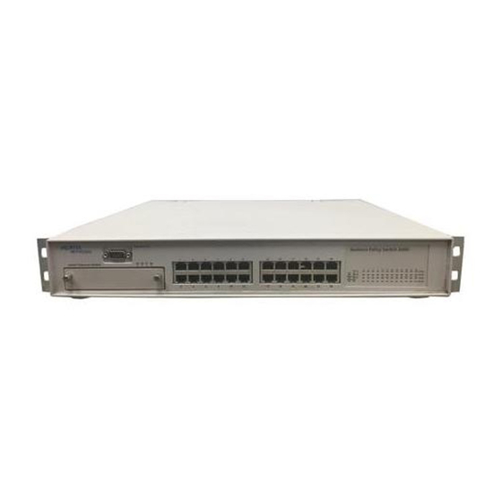
Page 36: Physical Description
Figure 1 Business Policy Switch 2000 Front panel Figure 2 shows the front-panel configuration for the Business Policy Switch 2000. Descriptions of the front-panel components follow the figure. For descriptions of the back-panel Business Policy Switch components, see panel” on page Using the Business Policy Switch 2000 Version 1.2... -
Page 37: Console Port
Figure 2 Business Policy Switch 2000 front panel Console Port 26 27 Uplink/Expansion Module Table 1 Business Policy Switch 2000 front-panel description Console port Uplink/expansion slot Port connectors LED display panel Console port The console port allows you to access the console interface (CI) screens and customize your network using the supplied menus and screens (see Chapter 3). -
Page 38: Uplink/Expansion Slot
The 10BASE-T/100BASE-TX switch ports also support half- and full-duplex mode operation (refer to Installing the Business Policy Switch 2000). The 10BASE-T/100BASE-TX RJ-45 ports can connect to 10 Mb/s or 100 Mb/s Ethernet segments or nodes. -
Page 39: Led Display Panel
LED display panel Figure 3 shows the Business Policy Switch LED display panel. See description of the LEDs. Figure 3 Business Policy Switch 2000 LED display panel Status Dwn RPSU Base Table 2 Business Policy Switch 2000 LED descriptions Label... - Page 40 Table 2 Business Policy Switch 2000 LED descriptions (continued) Label Type Color RPSU RPSU status Green Cas Up Stack mode Green Amber Amber Green Cas Dwn Stack mode Green Amber Amber Green State Meaning The switch is connected to the RPSU and can receive power if needed.
- Page 41 Table 2 Business Policy Switch 2000 LED descriptions (continued) Label Type Color Base Base mode Green Amber 10/100 10/100 Mb/s Green port speed indicator Amber State Meaning The switch is configured as the stack base unit. The switch is not configured as the stack base unit (or is in standalone mode).
- Page 42 Table 2 Business Policy Switch 2000 LED descriptions (continued) Label Type Color Link Link status Green Activity Port activity State Meaning Valid communications link established. The communications link connection is bad or there is no connection to this port. Blinking The corresponding port is management disabled.
-
Page 43: Back Panel
Cascade Module slot (Figure For more information about cascade modules, see Installing the Cascade 400-ST1 Cascade Module. See your Nortel Networks sales representative for cascade module ordering information. Figure “Stack configurations” on page Using the Business Policy Switch 2000 Version 1.2... -
Page 44: Cooling Fans
Figure 1 on page 36.) When you install the switch, be sure to allow enough space on both sides of the switch for adequate air flow. See Installing the Business Policy Switch 2000 for detailed information. AC power receptacle The AC power receptacle accepts the AC power cord (supplied). For installation outside of North America, make sure that you have the proper power cord for your region. -
Page 45: Table 4 International Power Cord Specifications
220 or 230 VAC 50 Hz Single phase 100 or 120 VAC 50–60 Hz Single phase 240 VAC 50 Hz Single phase 240 VAC 50 Hz Single phase Using the Business Policy Switch 2000 Version 1.2 228FA 227FA 229FA 230FA... -
Page 46: Redundant Power Supply Unit (Rpsu) And Uninterruptible
Networks BayStack 10 Power Supply Unit and 200 Watt AC/DC Power Supply Module. The 100 Watt DC-DC Converter provides a plug-and-play redundant power supply unit for the Business Policy Switch 2000, as well as other products available from Nortel Networks. Contact your Nortel Networks sales representative for information about the Nortel Networks products that use the 100 Watt DC-DC Converter. -
Page 47: Features
“Ability to ping” on page 61 — “Improved STP Fast Learning Mode” on page 61 — “BootP menu item for a stack of only BPS 2000 switches” on page 62 • Introduced with software version 1.0 — “Policy-enabled networking” on page 62 —... -
Page 48: Cli Management System
BPS 2000 with software version 1.2 or across a Pure BPS 2000 Stack with software version 1.2. If you are working with more than 64 VLANs in a Pure BPS 2000 Stack and you change to a Hybrid Stack, you lose all VLANs. However, if you have up to 64 VLANs in the Pure BPS 2000 Stack and you change to a Hybrid Stack, you will retain all the VLANs. -
Page 49: Multiple Spanning Tree Protocol Groups
Starting with software version 1.2, the BPS 2000 supports multiple spanning tree groups (STGs). The BPS 2000 supports a maximum of 8 STGs, either all in one standalone switch or across a stack consisting of only BPS 2000 switches (Pure BPS 2000 Stack mode). - Page 50 256 VLANs. With a maximum of 8 STGs, on average, each STG will have 32 VLANs. In the default configuration of the BPS 2000, a single STG with the ID of 1 includes all ports on the switch. It is called the default STG. Although ports can be added to or deleted from the default STG, the default STG (STG1) itself cannot be deleted from the system.
-
Page 51: Stg Configuration Guidelines
STG. • When a tagged port belongs to more than one STG, the egress BPDUs are tagged to distinguish the BPDUs of one STG from those of another STG. Using the Business Policy Switch 2000 Version 1.2... - Page 52 Because some STP-compliant devices do not support tagging, you can configure whether to send tagged or untagged BPDUs, even from tagged ports, with the BPS 2000 with software version 1.2. The VLAN ID for the tagged BPDUs will be 4000+STG ID.
-
Page 53: Spanning Tree Fast Learning
Spanning Tree Fast Learning is an enhanced port mode supported by the BPS 2000. If you enable Spanning Tree Fast Learning on a port with no other bridges, the port is brought up more quickly following the switch initialization or a spanning tree change. -
Page 54: Sample Ascii Configuration File
Sample ASCII configuration file This section shows a sample ASCII configuration file. This file is an example only and shows a basic configuration for a standalone BPS 2000 that includes Multi-Link Trunking, VLANs, port speed and duplex, and SNMP configurations. - Page 55 ! ------------------------------------------------------- ! Examples of changing interface parameters ! ------------------------------------------------------- ! change speed of port 3 interface Fastethernet 3 speed 10 duplex half exit ! change speed of port 4 interface Fastethernet 4 Using the Business Policy Switch 2000 Version 1.2...
-
Page 56: Ip Manager List
Software Version 1.2 for complete information on using the CLI commands. IP manager list With software version 1.2, you can limit access to the management features of the BPS 2000 by defining the IP addresses allowed access to the switch. The features provided by the IP manager list are: •... -
Page 57: Policy-Enabled Networks With Qos Metering
1.2, and Reference for the Business Policy Switch 2000 Command Line Interface Software Version 1.2. Policy-enabled networks with QoS metering With version 1.1, the BPS 2000 supports the traffic policing, or metering, feature of IETF Differentiated Services (DiffServ) Quality of Service (QoS) architecture. Refer to “Policy-enabled networking”... -
Page 58: Eapol-Based Security
Installing Media Dependent Adapters (MDAs). EAPOL-based security BPS 2000 software version 1.1 provides support for security based on the Extensible Authentication Protocol over LAN (EAPOL), which uses the EAP as described in the IEEE Draft P802.1X to allow you to set up network access control on internal LANs. -
Page 59: Automatic Pvid
Automatic PVID With software version 1.1, the BPS 2000 provides the Automatic PVID feature for configuring virtual local area networks (VLANs). Refer to “Virtual Local Area Networks (VLANs)” on page 63 for more complete information on VLANs. Refer to Chapter 3 for information on configuring Automatic PVID using the Console Interface (CI) menus. -
Page 60: Figure 6 Vlan Broadcast Domains Within The Switch
Ports 2, 4, 10, 8, 6, and 11 are untagged members of VLAN 3. The PVID/VLAN association for port 8 is: PVID = 3. VLAN 3 VLAN 2 VLAN 1 Port 8 Port 6 PVID = 3 PVID = 1 Using the Business Policy Switch 2000 Version 1.2 Port 11 BS45019A... -
Page 61: Tabular Port Statistics
DM. Tabular port statistics With BPS 2000 software version 1.1, you can view all ports in an entire stack that have an error. If a particular port has no errors, it will not be displayed. -
Page 62: Bootp Menu Item For A Stack Of Only Bps 2000 Switches
BootP menu item for a stack of only BPS 2000 switches In a stack consisting only of BPS 2000 switches, you can perform BootP using the MAC address of the base unit. Refer to “BootP automatic IP configuration/MAC address” on page 79 information on BootP and MAC addresses. -
Page 63: Virtual Local Area Networks (Vlans)
For information on configuring QoS using the Console Interface (CI) menus, refer to Chapter 3. To configure this feature using the Web-based management system, refer to Using Web-based Management for the Business Policy Switch 2000 Software Version 1.2. To use Device Manager (DM) to configure QoS, refer to Reference for the Business Policy Switch 2000 Management Software Version 1.2. - Page 64 The default setting for AutoPVID is Off; you must enable this feature. • Protocol-based VLANs A protocol-based VLAN is a VLAN in which you assign your switch ports as members of a broadcast domain, based on the protocol information within the packet. Protocol-based VLANs can localize broadcast traffic and assure that only the protocol-based VLAN ports are flooded with the specified protocol type packets.
-
Page 65: Using 256 Vlans
Independent VLAN Learning (IVL) mode—Each VLAN uses a unique forwarding database. The IVL mode is only an option when using the Business Policy Switch 2000; you must use the SVL mode when operating a hybrid stack. Business Policy Switches support up to 64 VLANs (port-, protocol-, or MAC SA-based), including VLAN #1 which is always port-based. -
Page 66: Security
If you are working with more than 64 VLANs in a Pure BPS 2000 Stack and you change to a Hybrid Stack, you lose all VLANs. However, if you have up to 64 VLANs in the Pure BPS 2000 Stack and you change to a Hybrid Stack, you will retain all the VLANs. - Page 67 MAC address-based security features for the Business Policy Switch. This example assumes that the switch, the teachers’ offices and classrooms, and the library are physically secured. The student dormitory may (or may not be) physically secure. Using the Business Policy Switch 2000 Version 1.2...
-
Page 68: Figure 7 Business Policy Switch 2000 Security Feature
Figure 7 Business Policy Switch 2000 security feature RADIUS server Switch Student Dormitory Legend = Secure locked area In this configuration example, the following security measures are implemented: • The switch — RADIUS-based security is used to limit administrative access to the switch through user authentication (see security”... - Page 69 The exception is the printer, which is assigned as a single station with full bandwidth to that port. It is assumed that all PCs are password protected and that access to the library is physically secured. 70). Using the Business Policy Switch 2000 Version 1.2...
-
Page 70: Radius-Based Network Security
Specify which of your switch ports each MAC address is allowed to access. The options for allowed port access include: NONE, ALL, and single or multiple ports that are specified in a list, for example, 1/1-4,1/6,2/9. Using the Business Policy Switch 2000 Version 1.2... -
Page 71: Eapol-Based Security
Command Line Interface Software Version 1.2. EAPOL-based security BPS 2000 software version 1.1 provides support for security based on the Extensible Authentication Protocol over LAN (EAPOL), which uses the EAP as described in the IEEE Draft P802.1X to allow you to set up network access control on internal LANs. - Page 72 The following example illustrates how the BPS 2000, configured with the EAPOL-based security feature, reacts to a new network connection: • The switch detects a new connection on one of its ports. — The switch requests a user ID from the new client.
- Page 73 VLAN. The new VLAN configuration values are applied according to previously stored parameters (based on the user_id) in the Authentication server. The following VLAN configuration values are affected: • Port membership • PVID • Port priority Using the Business Policy Switch 2000 Version 1.2...
- Page 74 — Tunnel-Private-Group-Id: ASCII value 1 to 4094 (this value is used to identify the specified VLAN) • Port priority (vendor-specific) attributes — Vendor Id: value 562, Nortel Networks vendor Id — Attribute Number: value 1, Port Priority Using the Business Policy Switch 2000 Version 1.2...
- Page 75 You must also configure your BayStack 350/410-24T/450 switches and BPS 2000 for port-based VLANs and EAPOL security. (For information on configuring the BPS 2000, refer to the Chapter 3, Using Web-based Management for the Business Policy Switch 2000 Software Version 1.2, Reference for the Business Policy Switch 2000 Management Software Version 1.2, and Reference for the Business...
-
Page 76: Flash Memory Storage
The flash memory allows you to update the software image with a newer version without changing the switch hardware (see Chapter 3). An in-band connection between the switch and the TFTP load host is required to download the software image. -
Page 77: Configuration Parameters Storage
800 Mb/s in full-duplex mode. The Business Policy Switch can be configured with up to six MultiLink Trunks. The trunk members can be configured within a single unit in the stack or distributed between any of the units within the stack configuration (distributed trunking). -
Page 78: Port Mirroring (Conversation Steering)
MAC addresses is monitored. You can attach a probe device (such as a Nortel Networks StackProbe, or equivalent) to the designated monitor port For more information about the port mirroring feature, refer to “Network... -
Page 79: Bootp Automatic Ip Configuration/Mac Address
Beginning with software version 1.2, you can retrieve the ASCII configuration file name and configuration server address using BootP. With software 1.1 and a stack consisting only of BPS 2000 switches (Pure BPS 2000 Stack mode), you can perform BootP using the MAC address of the base unit. -
Page 80: Configuration And Switch Management
Java-based Device Manager Device Manager is a Java-based set of graphical network management applications used to configure and manage a Business Policy Switch. Refer to Reference for the Business Policy Switch 2000 Management Software Operations Software Version 1.2 for more information. •... -
Page 81: Multifield Packet Classification
With software version 1.2 and higher, the CLI is used to automate general management and configuration of the BPS 2000. Use the CLI through a Telnet connection or through the serial port on the console. Refer to Reference for the Business Policy Switch 2000 Command Line Interface Software Version 1.2 for complete information on using the CLI. -
Page 82: Table 5 Snmp Mib Support
82 Chapter 1 The Business Policy Switch 2000 to detailed management statistics. With SNMP management, you can configure SNMP traps (on individual ports) to generate automatically for conditions such as an unauthorized access attempt or changes in a port’s operating status. -
Page 83: Snmp Trap Support
Using Web-based Management for the Business Policy Switch 2000 Software Version 1.2, Reference for the Business Policy Switch 2000, Command Line Interface Software Version 1.2, and Reference for the Business Policy Switch 2000 Management Software Version 1.2. Supported standards and RFCs This section lists the standards and RFCs supported by the BPS 2000. -
Page 84: Standards
84 Chapter 1 The Business Policy Switch 2000 Standards The following IEEE Standards contain information germane to the Business Policy Switch 2000: • IEEE 802.1D (Standard for Spanning Tree Protocol) • IEEE 802.3 (Ethernet) • IEEE 802.1Q (VLAN Tagging) •... - Page 85 Chapter 1 The Business Policy Switch 2000 85 Using the Business Policy Switch 2000 Version 1.2...
- Page 86 86 Chapter 1 The Business Policy Switch 2000 208700-B...
-
Page 87: Network Configuration
The BPS 2000 software version 1.2 is compatible with BayStack 450 software version 4.1. When you are using a local console to access the BPS 2000 software version 1.2 features with a Hybrid, or mixed, stack (BPS 2000 and BayStack 450 and 410 switches in the same stack), you must plug your local console into a BPS 2000 unit. -
Page 88: Network Configuration Examples
64 VLANs for the entire stack. When you change from a Pure BPS 2000 Stack mode to a Hybrid Stack mode: • If you have up to 64 VLANs on the Pure BPS 2000 Stack, they will be retained when you change to a Hybrid Stack. •... -
Page 89: Desktop Switch Application
Up to 26 users Network Center - 26 users; each with dedicated 100 Mb/s bandwidth - Server with dedicated 100 Mb/s bandwidth - Network center with dedicated 100 Mb/s full-duplex bandwith (200 mb/s bidirectional) Using the Business Policy Switch 2000 Version 1.2 9795EA... -
Page 90: Figure 9 Business Policy Switch Used As A Segment Switch
90 Chapter 2 Network configuration Figure 9 Business Policy Switch used as a segment switch Before 10BASE-T hubs Server Network Center 10 Mb/s 100 Mb/s 200 Mb/s - 88 users share 10 Mb/s (10/88 Mb/s per user) - Server bottleneck (10 Mb/s bandwidth) -
Page 91: High-Density Switched Workgroup Application
100BASE-TX hub, and a 100 Mb/s server as well as 10 Mb/s connections to DTE (data terminal equipment). See the Nortel Networks library Web page www.nortelnetworks.com/ documentation for online documentation about the Nortel Networks Passport 1100 switch and the BayStack 303 and BayStack 304 switches. Using the Business Policy Switch 2000 Version 1.2... -
Page 92: Fail-Safe Stack Application
For an overview of the fail-safe stacking feature that is available for the Business Policy Switches, see 208700-B BayStack 303 switch 100BASE-TX Figure 11, the Passport 1100 switch is used as a backbone switch, “Business Policy Switch stack BayStack 304 switch 9841EA operation.”... -
Page 93: Business Policy Switch Stack Operation
1000 Mb/s Business Policy Switch stack operation BPS 2000 switches configured with Business Policy Switch software version 1.0 provide fail-safe stackability when you install the optional BayStack 400-ST1 Cascade Module. You can connect up to eight Business Policy Switches and... -
Page 94: Baystack 400-St1 Cascade Module
• “Redundant cascade stacking feature” on page 102 Note: If you are implementing a mixed stack with the Business Policy Switch and BayStack 450 and BayStack 410 switches, refer to Appendixes for configuration and interoperability information. BayStack 400-ST1 Cascade Module... -
Page 95: Unit Select Switch
Unit Select switch The Unit Select switch (up = Base) determines the base unit for the stack configuration (see “Base unit”). The Unit Select switch status is displayed on the Business Policy Switch LED display panel. When the Unit Select switch is in the Base (up) position, all other Unit Select switches in the stack configuration must be set to Off (down). -
Page 96: Base Unit
(Refer to Chapter 3 for information on renumbering the units using the console interface (CI) menus and to Using Web-based Management for the Business Policy Switch 2000 Software Version 1.2 for renumbering the units using the Web-based management system). For example, when you initially power up the stack, the base unit becomes unit 1... -
Page 97: Stack Mac Address
For this reason, you should always assign the temporary base unit as the base unit (set the Unit Select switch to Base) until the failed unit is repaired or replaced. -
Page 98: Removing A Unit From The Stack
As shown in 400-ST1 Cascade Module front panel provide the ability to stack up to 8 switches. With BPS-2000 MDAs installed in each switch, the stack can accommodate a maximum of 224 switch ports. Because stack parameters are associated with the base unit (see physical stack order depends on the base unit’s position and whether the stack is... -
Page 99: Figure 14 Stack Up Configuration Example
Cascade Cable (part number 303978-A) Cascade Cable (part number 303979-A) Chapter 2 Network configuration 99 Unit 8 Unit 7 Unit 6 Unit 5 Unit 4 Unit 3 Unit 2 Unit 1 9813EA Using the Business Policy Switch 2000 Version 1.2... -
Page 100: Stack Down Configurations
15, data flows from the base unit (unit 1) to the next switch, which is assigned as unit 2, and continues until the last switch in the stack is assigned as unit 8. The physical order of the switches is from top to bottom (unit 1 to unit 8). -
Page 101: Table 8 Stack Down Configuration Description
(GUI) that represents the stack (see Figure 15). Note: For this reason, Nortel Networks recommends that you always configure the top unit in the stack as the base unit. In any stack configuration, the following applies: •... -
Page 102: Redundant Cascade Stacking Feature
102 Chapter 2 Network configuration Redundant cascade stacking feature Business Policy Switches allow you to connect up to 8 units into a redundant cascade stack. If any single unit fails or if a cable is accidently disconnected, other units in the stack remain operational, without interruption. Figure 16 shows an example of how a stack configuration reacts to a failed or powered-down unit in the stack configuration:... -
Page 103: Figure 16 Redundant Cascade Stacking Feature
Table 9 Redundant cascade stacking descriptions Base unit Last unit Cascade cable (part number 303978-A) Cascade max-return cable (part number 303979-A) Chapter 2 Network configuration 103 Cascade A 9815EA Using the Business Policy Switch 2000 Version 1.2... -
Page 104: Ieee 802.1Q Vlan Workgroups
Business Policy Switches support up to 64 VLANs (maximum of 48 MAC source address-based VLANs) with IEEE 802.1Q tagging available per port. With software version 1.2, the BPS 2000 supports up to 256 VLANs (maximum of 48 MAC source addressed-based VLANs.) Note: Only standalone or pure stacks of BPS 2000 support 256 VLANs. -
Page 105: Ieee 802.1Q Tagging
Refer to Chapter 3, Using Web-based Management for the Business Policy Switch 2000 Software Version 1.2, Reference for the Business Policy Switch 2000 Command Line Interface Software Version 1.2, and Reference for the Business Policy Switch 2000 Management Software Version 1.2 for information on overriding the default values. - Page 106 VLANs to the same FID when it is running in the Hybrid Operational mode. This process is referred to as Shared VLAN Learning (SVL) in the IEEE 802.1Q specification. In the Pure BPS 2000 operational mode, a VLAN may either share its filtering database with other VLANs (SVL) or have its own filtering database, which is called independent VLAN learning (IVL).
-
Page 107: Figure 18 Default Vlan Settings
VLAN 2. Chapter 2 Network configuration 107 VLAN 1 Port 4 Port 5 Port 6 Data Outgoing (unchanged) Figure 19 through Using the Business Policy Switch 2000 Version 1.2 Port 7 Port 8 BS45010A Figure 24). -
Page 108: Figure 19 Port-Based Vlan Assignment
Before As shown in switch through port 5, which is configured as a tagged member of VLAN 2. The untagged packet remains unchanged as it leaves the switch through port 7, which is configured as an untagged member of VLAN 2. -
Page 109: Figure 21 Policy-Based Vlan Assignment
Before As shown in switch through port 5, which is configured as a tagged member of VLAN 3. The untagged packet remains unchanged as it leaves the switch through port 7, which is configured as an untagged member of VLAN 3. -
Page 110: Figure 23 802.1Q Tag Assignment
VLAN 2, and port 7 is configured as an untagged member of VLAN 2. Figure 23 802.1Q tag assignment PVID = 2 Tagged packet Data Before 208700-B Port 1 Port 2 Port 3 802.1Q Switch Port 6 Port 7 Port 8 Untagged member of VLAN 2 Tagged member of VLAN 2 BS45013A... -
Page 111: Vlans Spanning Multiple Switches
As shown in switch through port 5, which is configured as a tagged member of VLAN 2. However, the tagged packet is stripped (untagged) as it leaves the switch through port 7, which is configured as an untagged member of VLAN 2. -
Page 112: Vlans Spanning Multiple 802.1Q Tagged Switches
Figure 26 shows VLANs spanning multiple untagged switches. In this configuration, Switch S2 does not support 802.1Q tagging and you must use a single switch port on each switch for each VLAN. For this configuration to work properly, you must set spanning tree participation to Disabled (the STP is not supported across multiple LANs). -
Page 113: Figure 26 Vlans Spanning Multiple Untagged Switches
STP when using VLANs between untagged (non-802.1Q tagged) switches. Chapter 2 Network configuration 113 VLAN 2 Business Policy Switch 2000 Non-802.1Q tagging switch Figure 27 shows possible Using the Business Policy Switch 2000 Version 1.2 9800EA... -
Page 114: Shared Servers
Business Policy Switches allow ports to exist in multiple VLANs for shared resources, such as servers, printers, and switch-to-switch connections. It is also possible to have resources exist in multiple VLANs on one switch as shown in Figure In this example, clients on different broadcast domains share resources. The broadcasts from ports configured in VLAN 3 can be seen by all VLAN port members of VLAN 3. -
Page 115: Figure 28 Multiple Vlans Sharing Resources
VLAN 1 (PVID=1) VLAN 2 (PVID=2) VLAN 3 (PVID=3) In the above configuration, all of the switch ports are set to participate as VLAN port members. This arrangement allows the switch to establish the appropriate broadcast domains within the switch Refer to Chapter 1 for additional guidelines on configuring VLANs and spanning tree groups. -
Page 116: Figure 29 Vlan Broadcast Domains Within The Switch
116 Chapter 2 Network configuration Figure 29 VLAN broadcast domains within the switch Port 2 PVID = 2 VLAN 1 (PVID = 1) VLAN 2 (PVID = 2) VLAN 3 (PVID = 3) For example, to create a broadcast domain for each VLAN shown in... -
Page 117: Figure 30 Default Vlan Configuration Screen Example
13-18 19-24 ------ ------ UUUUUU UUUUUU Press Ctrl-C to return to Main Me Figure 29 Using the Business Policy Switch 2000 Version 1.2 Chapter 2 Network configuration 117 (Figure 30): [ Port-Based ] None [ 0x0000 [ Active Figure 30 are default settings (VLAN Name is optional). -
Page 118: Figure 31 Vlan Configuration Screen Example
118 Chapter 2 Network configuration Ports 2, 4, 6, 8, 10, and 11 are now untagged members of VLAN 3 as shown in Figure 29 Figure 31 VLAN Configuration screen example Create VLAN: Delete VLAN: VLAN Name: [test VLAN ] Management VLAN: [ Yes ] Now: 1 IVL/SVL: [ IVL ]... -
Page 119: Figure 32 Default Vlan Port Configuration Screen Example
Chapter 2 Network configuration 119 VLAN Port Configuration [ No [ No [ No [Port 1] [ 0 ] [ Untagged Access ] Disabled Press Ctrl-C to return to Main Menu. Using the Business Policy Switch 2000 Version 1.2 Figure 29 (Port Name is... -
Page 120: Vlan Workgroup Summary
Ports 2, 3, 4, 7, and 10 are in VLAN 2. • Port 8 is in VLAN 3. Because S4 does not support 802.1Q tagging, a single switch port on each switch must be used for each VLAN (see switches). -
Page 121: Figure 34 Vlan Configuration Spanning Multiple Switches
VLAN 1 (PVID=1) VLAN 2 (PVID=2) VLAN 3 (PVID=3) Chapter 2 Network configuration 121 Business Policy Switch 2000 Both ports are tagged members of VLAN 1 and VLAN 2 Non-802.1Q tagging switch Using the Business Policy Switch 2000 Version 1.2 9802EA... -
Page 122: Vlan Configuration Rules
VLAN reacts in any network topology: • You must be in the Pure BPS 2000 Stack mode and using software version 1.2 to be able to configure between 65 and 256 VLANs. (You can configure up to 64 VLANs in Hybrid mode.) •... - Page 123 Business Policy Switch. As shown in Figure 35, a non-IP Multicast filtering switch causes IP Multicast traffic to be sent to all segments on the local subnet. Chapter 2 Network configuration 123 Using the Business Policy Switch 2000 Version 1.2...
-
Page 124: Figure 35 Ip Multicast Propagation With Igmp Routing
Non-IP Multicast membership report The Business Policy Switch can automatically set up IP Multicast filters so the IP Multicast traffic is only directed to the participating end nodes (see Figure 36, switches S1 to S4 represent a LAN connected to an IP Multicast router. -
Page 125: Figure 36 Business Policy Switch Filtering Ip Multicast Streams (1 Of 2)
Switch S1 treats the consolidated proxy reports from S2 and S4 as if they were reports from any client connected to its ports, and generates a consolidated proxy report to the designated router. In this way, the router receives a single consolidated report from that entire subnet. -
Page 126: Figure 37 Business Policy Switch Filtering Ip Multicast Streams (2 Of 2)
IP Multicast Figure 37 Business Policy Switch filtering IP multicast streams (2 of 2) Internet The consolidated proxy report generated by the switch remains transparent to layer 3 of the International Organization for Standardization, Open Systems Interconnection (ISO/OSI) model. -
Page 127: Igmp Snooping Configuration Rules
VLANs, IGMP, and spanning tree groups and Chapter 3. See also Appendix D for configuration flowcharts that can help you use this feature. Chapter 2 Network configuration 127 Using the Business Policy Switch 2000 Version 1.2... -
Page 128: Ieee 802.1P Prioritizing
Port 6 Untagged member of VLAN 2 Outgoing untagged packet (unchanged) The newly tagged frame is read within the switch and sent to the port’s high or low transmit queue for disposition. 208700-B Tagged member Port 2 Port 3 of VLAN 2 (Port 5) -
Page 129: Multilink Trunks
Note: For guidelines on configuring VLANs, STGs, and MLT, refer to Chapter 1. MultiLink Trunks allow you to group up to four switch ports together to form a link to another switch or server, thus increasing aggregate throughput of the interconnection between the devices (up to 800 Mb/s in full-duplex mode). -
Page 130: Figure 39 Switch-To-Switch Trunk Configuration Example
(NIC). For this reason, FS1 does not require a trunk assignment. FS2 is a single MAC server (with a four-port NIC) and is set up as trunk configuration T1. 208700-B Business Policy Switch 2000 Business Policy Switch 2 Business... -
Page 131: Client/Server Configuration Using Multilink Trunks
Clients accessing data from the servers (FS1 and FS2) are provided with maximized bandwidth through trunks T1, T2, T3, T4, and T5. Trunk members (the ports making up each trunk) do not have to be consecutive switch ports; you can select ports randomly, as shown by T5. -
Page 132: Before You Configure Trunks
For detailed information about configuring trunks, see Chapter 3. Before you configure trunks When you create and enable a trunk, the trunk members (switch ports) take on certain settings necessary for correct operation of the MultiLink Trunking feature. Before you configure your MultiLink Trunk, you must consider these settings,... -
Page 133: Multilink Trunking Configuration Rules
Ensure that the chosen switch ports are set to Enabled, using either the Port Configuration screen (see Chapter 3) or other network management system. Trunk member ports must have the same VLAN configuration. All network cabling should be complete and stable before configuring any trunks, to avoid configuration errors. -
Page 134: How The Multilink Trunk Reacts To Losing Distributed Trunk Members
134 Chapter 2 Network configuration • When you set any trunk member to Disabled (not active) through the Port Configuration screen or through network management, the trunk member is removed from the trunk. The trunk member has to be reconfigured to rejoin the trunk through the Trunk Configuration screen on the CI menus, or another management system. -
Page 135: Spanning Tree Considerations For Multilink Trunks
Chapter 2 Network configuration 135 BPS2000 MDA BPS2000 MDA BPS2000 MDA BPS2000 CPU PS1 PS2 FAN Figure 43 Using the Business Policy Switch 2000 Version 1.2 Business Policy Switch 2000 Unit 1 Unit 2 Unit 3 Unit 4 Unit 5... -
Page 136: Figure 43 Path Cost Arbitration Example
The switch can also detect trunk member ports that are physically misconfigured. For example, in configured correctly to trunk member ports 7, 9, and 11 of Switch S2. The Spanning Tree Port Configuration screen for each switch shows the port state field for each port in the Forwarding state. -
Page 137: Figure 44 Example 1: Correctly Configured Trunk
13, the Spanning Tree Port Configuration screen for Switch S1 changes to show port 6 in the Blocking state Chapter 2 Network configuration 137 Business Policy Switch 2000 S2 Port Configuration screen (Figure 45). Using the Business Policy Switch 2000 Version 1.2 Business Policy Switch 2 9808EA... -
Page 138: Additional Tips About The Multilink Trunking Feature
For example, if you change spanning tree parameters for any trunk member, the spanning tree parameters for all trunk members change. 208700-B S2 Port Configuration screen [Blocking] Business Policy Switch 2 Business Policy Switch 2000 9809EA... -
Page 139: Port Mirroring
Note: A probe device, such as the Nortel Networks StackProbe equivalent, must be connected to the designated monitor port to use this feature (contact your Nortel Networks sales agent for details about the StackProbe). The following sections provide sample configurations for both monitoring modes... -
Page 140: Port-Based Mirroring Configuration
23 is designated as the monitor port for ports 24 and 25 of Switch S1. Although this example shows ports 24 and 25 monitored by the monitor port (port 23), any of the trunk members of T1 and T2 can also be monitored. -
Page 141: Figure 46 Port-Based Mirroring Configuration Example
Y (conversations between port X and port Y). Chapter 2 Network configuration 141 StackProbe Monitor port Figure 46, the designated monitor port Using the Business Policy Switch 2000 Version 1.2 (port 23) Business Policy Switch 2 Port Y (port 24) -
Page 142: Figure 47 Port Mirroring Configuration Port-Based Screen Example
142 Chapter 2 Network configuration As shown in the Port Mirroring Configuration screen example is designated as the Monitor Port for ports 24 and 25 in Switch S1. Note: The Unit value (in the Unit/Port field) is not configurable when the switch is operating standalone. -
Page 143: Address-Based Mirroring Configuration
Monitor all traffic received by or transmitted by address A. • Monitor all traffic transmitted by address A to address B. Chapter 2 Network configuration 143 StackProbe Monitor port Address B Using the Business Policy Switch 2000 Version 1.2 (port 23) BS45033A... - Page 144 Figure 49 shows the Port Mirroring Configuration screen setup for this example. In this example, port 23 becomes the designated Monitor Port for Switch S1 when you press Enter in response to the [Yes] screen prompt. Note: The screen data displayed at the bottom of the screen changes to show the new currently active port mirroring configuration after you press Enter.
-
Page 145: Port Mirroring Configuration Rules
When you configure a port as a monitor port, the port is automatically disabled from participating in the spanning tree. When you reconfigure the port as a standard switch port (no longer a monitor port), the port is enabled for spanning tree participation. - Page 146 146 Chapter 2 Network configuration • VLAN configuration settings for any ports configured for port-based mirroring cannot be changed. Use the Port Mirroring Configuration screen to disable port mirroring (or reconfigure the port mirroring ports), then change the VLAN configuration settings. •...
-
Page 147: Using The Console Interface
The BPS 2000 software version 1.2 is compatible with BayStack 450 software version 4.1. When you are using a local console to access the BPS 2000 software version 1.2 features with a Hybrid, or mixed, stack (BPS 2000 and BayStack 450 and 410 switches in the same stack), you must plug your local console into a BPS 2000 unit. -
Page 148: Accessing The Ci Menus And Screens
64 VLANs for the entire stack. When you change from a Pure BPS 2000 Stack mode to a Hybrid Stack mode: • If you have up to 64 VLANs on the Pure BPS 2000 Stack, they will be retained when you change to a Hybrid Stack. •... -
Page 149: Using The Ci Menus And Screens
To clear a string field: — Position the cursor in the string field. — Press [Ctrl]-K. • To return to the previous menu, press [Ctrl]-R. Chapter 3 Using the console interface 149 Using the Business Policy Switch 2000 Version 1.2... -
Page 150: Screen Fields And Descriptions
Display Event Log Reset to Default Settings Command Line Interface Only appears when the switch is participating in a stack configuration. Only appears when a gigabit MDA is installed in one or more units in a stack configuration. 208700-B MAC Address Table MAC Address Security Config. -
Page 151: Main Menu
The CI screens for your specific switch model will show the correct model name in the main menu screen title and the correct number of ports and port types in the Port Configuration screen. Note: The field values shown in the CI screens in this section are provided as examples only. -
Page 152: Figure 51 Console Interface Main Menu
MAC address. This screen also contains three user-configurable fields: sysContact, sysName, and sysLocation. When the switch is part of a stack configuration, this screen also displays the base unit identification, the number of units configured in the stack, and the local unit stack number. - Page 153 • When you select this option, the switch resets, runs a self-test, then displays the Nortel Networks logo screen. Press [Ctrl]-Y to access the Business Policy Switch main menu. Chapter 3 Using the console interface 153 screen”...
- Page 154 • When you select this option, the switch resets, runs a self-test, then displays the Nortel Networks logo screen. Press [Ctrl]-Y to access the Business Policy Switch main menu. NOTE: The following items do NOT reset: Stack Operational Mode, Reset Count, and Reason for Last Reset.
-
Page 155: Ip Configuration/Setup Screen
[ 0.0.0.0 ] 0.0.0.0 [ 0.0.0.0 ] [ No ] Stack UpTime: 01:07:54 mode” on page 157 Using the Business Policy Switch 2000 Version 1.2 52) allows you to set or modify the Last BootP --------------- 0.0.0.0 0.0.0.0 0.0.0.0 Reset Count: 13 “Choosing a... -
Page 156: Table 11 Ip Configuration/Setup Screen Fields
Default Value Range In-Band Switch The in-band IP address of the switch. This field is not required for the operation of the IP Address stack. This field cannot use the same IP address used for the stack. Default Value... -
Page 157: Choosing A Bootp Request Mode
0 and 255, separated by a decimal point 0.0.0.0 (no IP address assigned) Four-octet dotted-decimal notation, where each octet is represented as a decimal value, between 0 and 255, separated by a decimal point No, Yes Using the Business Policy Switch 2000 Version 1.2... -
Page 158: Bootp When Needed
• BootP or Last Address. BootP When Needed Allows the switch to request an IP address if one has not already been set from the console terminal. When selected, this mode operates as follows: • When the IP data is entered from the console terminal, the data becomes the in-use address of the switch and BootP requests are not broadcast. -
Page 159: Bootp Disabled
IP address is currently in use, these actions take effect only after the switch is reset or power cycled. With software 1.1 and a stack consisting only of BPS 2000 switches (Pure BPS 2000 Stack mode), you can perform BootP using the MAC address of the base unit. -
Page 160: Snmp Configuration Screen
160 Chapter 3 Using the console interface SNMP Configuration screen The SNMP Configuration screen SNMP configuration parameters. To open the SNMP Configuration screen: ➨ Choose SNMP Configuration (or press m) from the main menu. Figure 53 SNMP Configuration screen Read-Only Community String: Read-Write Community String: Trap #1 IP Address: Community String:... -
Page 161: Table 12 Snmp Configuration Screen Fields
Autotopology 1 The Trap IP Address and Community String fields can be set using a MIB table (in a Nortel Networks proprietary MIB). The status of the row in the MIB table can be set to Ignore. If the row status is set to Ignore, the fields appear to be set when viewed from the console terminal;... -
Page 162: System Characteristics Screen
MAC Address: 00-80-2C-8D-23-DF Reset Count: Last Reset Type: Management Reset Power Status: Primary Power Local MDA Type: None sysDescr: Business Policy Switch 2000 HW:AB3 FW:V1.2 SW:v1.2.0.0 ISVN: 2 sysObjectID: 1.3.6.1.4.1.45.3.40.1 sysUpTime: 0 days, 0:11:3 sysServices: sysContact: sysName: sysLocation: Enter text, press <Return> or <Enter> when complete. -
Page 163: Table 13 System Characteristics Screen Fields
Read-only field that indicates the operation mode of the unit, for example: • When the unit is part of a stack configuration, the (read-only) field indicates the unit is operational in a stack, and lists the current unit number of this switch. In this example (see •... -
Page 164: Switch Configuration Menu Screen
Note: The High Speed Flow Control Configuration option only appears when an optional Gigabit MDA is installed. Choose Switch Configuration (or press w) from the main menu to open the Switch Configuration Menu screen 208700-B Zero-length string... -
Page 165: Figure 55 Switch Configuration Menu Screen
167). This screen allows you to view all MAC addresses and their associated port or trunk that the switch has learned, or to search for a particular MAC address (to see if the switch has learned the address). Displays the MAC Address Security Configuration menu (see... - Page 166 201). This screen allows you to configure a specific switch port, all switch ports or, when in a stack configuration, all stack ports. Only appears when an optional Gigabit MDA is installed in the Uplink Module slot. When the Gigabit MDA is installed, selecting this option...
-
Page 167: Mac Address Table Screen
Operational Mode screen” on page 230 • The Pure BPS 2000 Stack Mode field indicates that your stack contains only Business Policy Switches. • The Hybrid Stack Mode field indicates that your stack consists of switches other than, or in addition to, Business Policy Switch(es). -
Page 168: Figure 56 Mac Address Table Screen
Table 15 MAC Address Table screen fields Field Description Aging Time Specifies how long a learned MAC address remains in the switch’s forwarding database. If an entry is inactive for a period of time that exceeds the specified aging time, the address is removed. Default Value... -
Page 169: Mac Address Security Configuration Menu Screen
The MAC Address Security Configuration Menu screen specify a range of system responses to unauthorized network access to your switch. The system response can range from sending a trap to disabling the port. The network access control is based on the MAC addresses of the authorized stations. -
Page 170: Figure 57 Mac Address Security Configuration Menu Screen
MAC Address Security Table screen. MAC Address Security Displays the MAC Address Security Table screen (see Table... Security Table screens” on page MAC addresses that are allowed to access the switch. 208700-B Press Ctrl-C to return to “MAC 169). This screen 173”). -
Page 171: Mac Address Security Configuration Screen
Chapter 3 Using the console interface 171 (Figure 58) allows you to [ Disabled ] [ Disabled ] [ Disabled ] [ Disabled ] [ Disabled ] [ Disabled ] Press Ctrl-C to return to Main Menu. Using the Business Policy Switch 2000 Version 1.2... -
Page 172: Table 17 Mac Address Security Configuration Fields
Default Range Partition Port on Intrusion This field value determines how the switch reacts to an intrusion event. When Detected an intrusion even is detected (see MAC Address Security field description) the specified switch port is set to Disabled (partitioned from other switch ports). -
Page 173: Mac Address Security Port Configuration Screen
Range Current Learning Mode Indicates the current learning mode for the switch ports. When this field is set to Learning in Progress, all source MAC addresses of any packets received on the specified port (or ports) are added to the MAC Security Table (maximum of 448 MAC address entries allowed). - Page 174 174 Chapter 3 Using the console interface To open the MAC Address Security Port Configuration screen: ➨ Choose MAC Address Security Port Configuration from the MAC Address Security Configuration Menu. 208700-B...
-
Page 175: Figure 59 Mac Security Port Configuration Screen (1 Of 2)
Use space bar to display choices, press <Return> or <Enter> to select choice. Press Ctrl-R to return to previous menu. Chapter 3 Using the console interface 175 Press Ctrl-C to return to Main Menu. Press Ctrl-C to return to Main Menu. Using the Business Policy Switch 2000 Version 1.2 More... -
Page 176: Mac Address Security Port Lists Screens
Displays the trunk number if the port is a member of that trunk. Default Security This field value determines whether or not security is enabled or disabled on the port level or switch level. Default Range MAC Address Security Port Lists screens... -
Page 177: Figure 61 Mac Address Security Port Lists Screens
Press Ctrl-C to return to Main Menu. More... Press Ctrl-C to return to Main Menu. Press Ctrl-C to return to Main Menu. Press Ctrl-C to return to Main Menu. Using the Business Policy Switch 2000 Version 1.2 Screen 2 Screen 3 Screen 4 Screen 5... -
Page 178: Port List Syntax
When you enter a port list in a stack configuration, you must specify either a unit/ port list, NONE, or ALL. In a stack configuration, ALL indicates all of the stack port; whereas, in a standalone scenario, ALL indicates all of the switch ports. Note: NONE and ALL must be entered in uppercase characters as shown in the screen prompt. -
Page 179: Accelerator Keys For Repetitive Tasks
1/3,2/7,2/9,3/1-4 [Return]. This method can be cumbersome. Chapter 3 Using the console interface 179 (Figure 62 on page 178). You can modify the 178, S3 shows the Port List field Using the Business Policy Switch 2000 Version 1.2... - Page 180 180 Chapter 3 Using the console interface As an alternative method instead, you can highlight the field and then enter +2/9 [Return]. The existing field keeps the previous list and adds the new port number (2/9) between ports 2/7 and 3/14. (If you choose to add port 2/8 to the existing port number list, the field accepts the new port 2/8 but shows the new port number list field as: 1/3,2/7-8,3/1-4.) Removing a port from an existing port number list...
-
Page 181: Mac Address Security Table Screens
Press Ctrl-P to display previous screen. Enter MAC Address, xx-xx-xx-xx-xx-xx, press <Return> or <Enter> when complete. Press Ctrl-R to return to previous menu. Press Ctrl-C to return to Main Menu. Using the Business Policy Switch 2000 Version 1.2 (Figure 63) that you Allowed Source... -
Page 182: Figure 64 Mac Address Security Table Screen
MAC Address Allows you to specify up to 448 MAC addresses that are authorized to access the switch. You can specify the ports that each MAC address is allowed to access using the Allowed Source field (see next field description). The... -
Page 183: Eapol Security Configuration Screen
Chapter 3 Using the console interface 183 - (Blank field) A single unit/port or a port list value (for example, 1/3, 1/6, 3/4, S1, S5, etc.). (Figure 65) allows you to selectively Using the Business Policy Switch 2000 Version 1.2... -
Page 184: Figure 65 Eapol Security Configuration Screen
Option Description EAPOL Administrative Allows you to enable or disable EAPOL for your switch or stack. When this field is set to disabled (the default state), the Operational Status for all of the State switch/stack ports is set to Authorized (no security restriction). - Page 185 The All value is also useful when you want to apply modified field values to most of, but not all of, your switch’s ports. For example, if you want to apply modified field values to 23 of your switch’s 24 ports, it may be easier to apply the All value in the Port field, and then reconfigure the single port back to its original values.
- Page 186 Allows you to specify the time period between any single EAPOL authentication failure and the start of a new EAPOL authentication attempt. Default Range Transmit Period Allows you to specify how long the switch waits for the supplicant to respond to EAP Request/Identity packets. Default Range Supplicant Timeout Allows you to specify how long the switch waits for the supplicant to respond to all EAP packets, except EAP Request/Identity packets.
-
Page 187: Vlan Configuration Menu Screen
VLANs of the same protocol type; however, tagged ports can.) Note: Only standalone or pure stacks of BPS 2000 support 256 VLANs. A mixed stack that consists of BPS 2000 and BayStack 450 switches has only 64 VLANs. Refer to “Using 356 VLANs” in Chapter 1 for more information on using 256 VLANs. -
Page 188: Figure 66 Vlan Configuration Menu Screen
Note: Refer to Chapters 1 and 2 for detailed information about configuring VLANs. To open the VLAN Configuration Menu: ➨ Choose VLAN Configuration (or press v) from the Switch Configuration Menu screen. Figure 66 VLAN Configuration Menu screen Use arrow keys to highlight option, press <Return> or <Enter> to select option. -
Page 189: Vlan Configuration Screen
When you configure ports as VLAN port members, they become part of a set of ports that form a broadcast domain for a specific VLAN. You can assign switch ports, whether standalone or stacked unit ports, as VLAN port members of one or more VLANs. - Page 190 190 Chapter 3 Using the console interface You can add or remove port members from a VLAN in accordance with the IEEE 802.1Q tagging rules. Refer to Chapter 2 for a description of important terms used with 802.1Q VLANs. You can also use this screen to create and to delete specific VLANs, to assign VLAN names, and to assign any VLAN as the management VLAN.
-
Page 191: Figure 67 Vlan Configuration Screen
Protocol Id (PID): [ None User-Defined PID: VLAN State: Port Membership 13-18 19-24 ------ ------ UUUUUU UUUUUU UUUUUU UUUUUU 2 to 4094 Using the Business Policy Switch 2000 Version 1.2 [ Port-Based [ 0x0000 [ Active Press Ctrl-C to return to... - Page 192 To set this field, the VLAN State field value must be Inactive. IVL is a Business Policy Switch-only feature. The IVL option is enabled only in Pure BPS 2000 Stack mode. The SVL option is enabled in the Hybrid Stack mode. See...
- Page 193 (T) or as a non-VLAN port member (-). The Port Membership fields are displayed in six-port groups (for example, 1-6, 7-12, 13-18). The number of ports displayed depends on the switch model or type of optional MDA installed in the Uplink Module slot. Default...
-
Page 194: Table 24 Predefined Protocol Identifier (Pid)
194 Chapter 3 Using the console interface Predefined Protocol Identifier (PID) description Table 24 defines the standard protocol-based VLANs and PID types that are supported by the Business Policy Switch and BayStack 450 and BayStack 410 switches. Table 24 Predefined Protocol Identifier (PID) PID Name... -
Page 195: Table 25 Reserved Pids
8100 IEEE 802.1Q for tagged frames 8137, 8138 80D5 SNA Ether2 86DD Ipv6 Ether2 8808 Ipx 802.3 Ipx 802.3 Ethernet 802.2 Ipx 802.2 Ethernet 802. Chapter 3 Using the console interface 195 Using the Business Policy Switch 2000 Version 1.2... -
Page 196: Mac Address Configuration For Mac-Sa-Based Vlan Screen
196 Chapter 3 Using the console interface MAC Address Configuration for MAC-SA-Based VLAN screen The MAC Address Configuration for MAC-SA Based VLAN screen allows you to configure specific MAC SA-based VLANs. This screen allows you to select a MAC SA-based VLAN. Figure 68 MAC Address Configuration for MAC-SA Based VLAN screen MAC Address Configuration for MAC-SA Based VLAN MAC-SA Based VLAN:... -
Page 197: Vlan Port Configuration Screen
Chapter 1 for more information on configuring ports for tagged or untagged frames. You can also prioritize the order in which the switch forwards packets, on a per-port basis (see Chapters 1 and 2). Refer to Chapter 4 “Policy-enabled networks,”... -
Page 198: Figure 69 Vlan Port Configuration Screen
Tagged Trunk Disabled Description Allows you to select a switch in your stack. To view another switch, type its switch number and press [Enter], or press the spacebar to toggle the switch numbers. Allows you to select the number of the port you want to view or configure. - Page 199 PVID VLAN. They will no longer be classified based on the information within the packet, even if they are members of a policy-based VLAN. Default Untagged Access Range Untagged Access, Tagged Trunk Using the Business Policy Switch 2000 Version 1.2...
-
Page 200: Vlan Display By Port Screen
VLAN Display by Port screen The VLAN Display by Port screen characteristics associated with a specified switch port. Choose VLAN Display by Port (or press d) from the VLAN Configuration Menu screen to open the VLAN Display by Port screen. -
Page 201: Port Configuration Screen
Field Description Unit Allows you to select a switch in your stack. To view another switch, type its switch number and press [Enter], or press the spacebar to toggle the switch numbers. Port Allows you to select the number of the port you want to view. To view another port, type its port number and press [Enter], or press the spacebar on your keyboard to toggle the port numbers. -
Page 202: Figure 71 Port Configuration Screen (1 Of 2)
[ Enabled [ Enabled Down [ Enabled Down Switch [ Enable Stack [ Enable Press Ctrl-P to display choices for ports 1-14. Use space bar to display choices, press <Return> or <Enter> to select choice. Press Ctrl-R to return to previous menu. -
Page 203: Table 29 Port Configuration Screen Fields
(for example, the field values in row 2 apply to switch port 2). The values that you set in the Switch row will affect all switch ports and, when the switch is part of a stack, the values that you set in the Stack row will affect all ports in the entire stack (except the Gigabit MDA ports or fiber optic ports, when installed). -
Page 204: High Speed Flow Control Configuration Screen
Note: This screen only appears when an optional Gigabit MDA is installed in the Uplink Module slot. ➨ Choose High Speed Flow Control Configuration (or press h) from the Switch Configuration Menu screen to open the High Speed Flow Control Configuration screen. -
Page 205: Figure 73 High Speed Flow Control Configuration
Disabled Preferred Phy: [ Right ] Active Phy: Right Press Ctrl-C to return to Main Menu. Enabled Enabled, Disabled “Choosing a high speed flow control Disabled Disabled, Symmetric, Asymmetric Using the Business Policy Switch 2000 Version 1.2 mode” for details... -
Page 206: Choosing A High Speed Flow Control Mode
Gigabit full-duplex link. If the receive port buffer becomes full, the Business Policy Switch issues a flow-control signal to the device at the other end of the link to suspend transmission. When the receive buffer is no longer full, the switch issues a signal to resume the transmission. -
Page 207: Multilink Trunk Configuration Menu Screen
To open the MultiLink Trunk Configuration Menu screen: ➨ Choose MultiLink Trunk Configuration (or press t) from the Switch Configuration Menu screen. Chapter 3 Using the console interface 207 (Figure 74) allows you to select Using the Business Policy Switch 2000 Version 1.2... -
Page 208: Multilink Trunk Configuration Screen
MultiLink Trunk Displays the MultiLink Trunk Configuration screen Configuration... allows you to configure up to six MultiLink Trunks within a standalone switch or within a stack configuration. You can group up to four switch ports together to form each trunk. -
Page 209: Figure 75 Multilink Trunk Configuration Screen
MultiLink Trunking feature. These default settings can affect the correct operation of your configured network. If you disable a trunk, you may need to reconfigure the specific trunk members switch ports to return to the previous switch configuration. See Chapter 1 for more information. -
Page 210: Table 32 Multilink Trunk Configuration Screen Fields
Description Trunk Column header for the read-only fields in this screen. The read-only data displayed in the Trunk column indicates the trunk (1 to 6) that corresponds to the switch ports specified in the user-configurable Trunk Members fields. Trunk Members... -
Page 211: Multilink Trunk Utilization Screen
25.0% 6/13 35.0% 6/14 30.0% 5/19 40.0% 5/20 25.0% Press Ctrl-C to return to Main Menu. Using the Business Policy Switch 2000 Version 1.2 Figure 77) allows you to Last 30 Minutes Last Hour --------------- --------- 70.0% 90.0% 55.0% 80.0% 45.0%... -
Page 212: Figure 77 Multilink Trunk Utilization Screen (2 Of 2)
Description Trunk Column header for the read-only fields in this screen. The read-only data displayed in this column indicates the trunk (1 to 6) that corresponds to the switch ports specified in the Port field. Traffic Type Allows you to choose the traffic type to be monitored for percent of bandwidth utilization (see Range). -
Page 213: Port Mirroring Configuration Screen
Port Mirroring Configuration screen, in a stack configuration, where port 12 (in stack unit 3) is designated as the monitoring port for ports 5 and 6 of stack unit 4. When installed as a standalone switch, the screen does not display the (Unit/) field designation. -
Page 214: Figure 78 Port Mirror Configuration Screen
214 Chapter 3 Using the console interface Figure 78 Port Mirror Configuration screen Monitoring Mode: Monitor Unit/Port: Currently Active Port Mirroring Configuration --------------------------------------------- Monitoring Mode -> Port Unit X: Port X: Use space bar to display choices, press <Return> or <Enter> to select choice. Press Ctrl-R to return to previous menu. - Page 215 When installed as a standalone switch, the screen does not display the (Unit/) field designation. This port will be monitored according to the value of Port Y in the...
-
Page 216: Rate Limiting Configuration Screen
216 Chapter 3 Using the console interface Table 35 Monitoring modes Field Port-based: Disabled -> Port X Port X -> <-> Port X -> Port X Port Y -> -> Port X and Port Y -> <-> Port X and Port Y <-> Address-based: Disabled Address A... -
Page 217: Figure 79 Rate Limiting Configuration Screen (1 Of 2)
[ None ] 15.0% [ None ] 12.0% [ None ] 44.0% [ None ] 34.0% Press Ctrl-C to return to Main Menu. Using the Business Policy Switch 2000 Version 1.2 Last Hour Last 24 Hours --------- ------------- 22.0% 23.0% 27.0% 55.0% 24.0%... -
Page 218: Figure 80 Rate Limiting Configuration Screen (2 Of 2)
[ Both [ Both [ Both [ Both Switch[ Both Stack [ Both Press Ctrl-P to display choices for ports 1-14. Use space bar to display choices, press <Return> or <Enter> to select choice. Press Ctrl-R to return to previous menu. -
Page 219: Igmp Configuration Menu Screen
Indicates the switch port numbers that correspond to the field values in that row of the screen (for example, the field values in row 2 apply to switch port 2). Note that the values applied in the Switch or Stack row (last 2 rows) affect all standalone switch ports or all switch ports in a stack. -
Page 220: Figure 81 Igmp Configuration Menu Screen
220 Chapter 3 Using the console interface To open the IGMP Configuration Menu screen: ➨ Choose IGMP Configuration (or press g) from the Switch Configuration Menu screen. Figure 81 IGMP Configuration Menu screen Use arrow keys to highlight option, press <Return> or <Enter> to select option. -
Page 221: Igmp Configuration Screen
Unit # field designation. In this example, switch ports 8 and 14 of unit 1, ports 2 and 6 of unit 2, and port 16 of unit 4 are set to receive/transmit multicast from the local multicast router. The configured ports are VLAN port members of VLAN 5. -
Page 222: Figure 82 Igmp Configuration Screen
222 Chapter 3 Using the console interface Figure 82 IGMP Configuration screen 7-12 ------ ------ Unit #1 ------ -X---- Unit #2 -X---X ------ KEY: X = IGMP Port Member (and VLAN Member), - = Not an IGMP Member Use space bar to display choices, press <Return> or <Enter> to select choice. - Page 223 Default Value Range Robust Value Allows a user to set the switch to offset expected packet loss on a subnet. If packet losses on a subnet are unacceptably high, the Robust Value field can be increased to a higher value.
-
Page 224: Multicast Group Membership Screen
Description Static Router Ports Allows a user to assign switch ports to any port that has a path to a multicast router. When the unit is part of a stack configuration, the screen displays the unit numbers of the switches configured in the stack, along with the corresponding ports. -
Page 225: Figure 83 Multicast Group Membership Screen
Displays all of the IP Multicast group addresses that are currently active on the associated port. Displays the port numbers that are associated with the IP Multicast group addresses displayed in the IP Multicast group address field. Using the Business Policy Switch 2000 Version 1.2 Port: Port: Port:... -
Page 226: Port Statistics Screen
Port Statistics screen The Port Statistics screen about any switch or port in a stacked or standalone configuration. The screen is divided into two sections (Received and Transmitted) so that you can compare and evaluate throughput or other port parameters. All screen data is updated approximately every 2 seconds. -
Page 227: Figure 84 Port Statistics Screen
Total Octets: Packets 64 bytes: Collisions: Single Collisions: Multiple Collisions: Excessive Collisions: Deferred Packets: Late Collisions: Using the Business Policy Switch 2000 Version 1.2 Transmitted 65-127 bytes 128-255 bytes 256-511 bytes 512-1023 bytes 1024-1518 bytes Press Ctrl-Z to zero Press Ctrl-C to... -
Page 228: Table 40 Port Statistics Screen Fields
Description Unit Only appears if the switch is participating in a stack configuration. The field allows you to select the number of the unit you want to view or configure. To view or configure another unit, type its unit number and press [Enter], or press the spacebar on your keyboard to toggle the unit numbers. - Page 229 Late Collisions Indicates the total number of packet collisions that occurred after a total length of time that exceeded 512 bit-times of packet transmission. Chapter 3 Using the console interface 229 Using the Business Policy Switch 2000 Version 1.2...
-
Page 230: Stack Operational Mode Screen
Figure 85 Stack Operational Mode screen Current Stack Operational Mode: Pure BPS 2000 Stack Next Stack Operational Mode: [ Pure BPS 2000 Stack ] Stack BootP Mac Address Type: [ Use space bar to display choices, press <Return> or <Enter> to select choice. -
Page 231: Console/Comm Port Configuration Screen
Range Next Stack Operational Allows you to set the configuration modes of your stack. Press the spacebar to Mode toggle between Hybrid Stack and Pure BPS 2000 Stack options. Reboot the system to implement the change. Default Range Stack BootP Mac Allows you to set the location for the BootP MAC address. -
Page 232: Figure 86 Console/Comm Port Configuration Screen
Figure 86 Console/Comm Port Configuration screen Comm Port Data Bits: Comm Port Parity: Comm Port Stop Bits: Console Port Speed: Console Switch Password Type: Console Stack Password Type: Telnet Switch Password Type: Telnet Stack Password Type: Console Read-Only Switch Password:... - Page 233 [Invio]. Se la comunicazione cade, impostare il terminale della console in modo tale che corrisponda alla nuova impostazione della porta di servizio. None None, Local Password, RADIUS Authentication Using the Business Policy Switch 2000 Version 1.2...
- Page 234 Switch Password Console, or for Both), this field allows read-write password access to the CI of a standalone switch. Users can log in to the CI using the correct password (see default) and can change any parameter, except the stack passwords.
- Page 235 Si olvida las nuevas contraseñas, no podrá acceder al interfaz de la consola. En ese caso, póngase en contacto con Nortel Networks para obtener ayuda al respecto. Attenzione: In caso di modifica delle password predefinite nel sistema, assicurarsi di annotare le nuove password e di conservarle in un luogo sicuro.
- Page 236 Console, or for Both), this field allows read-write password access to the CI of any participating switch in a stack configuration. Users can log in to the CI using the correct password (see default), and can change any parameter, except the switch password.
-
Page 237: Identify Unit Numbers
1645 0 to 65536 Null string (which will not authenticate) Any contiguous ASCII string that contains at least 1 printable character, up to a maximum of 35 Using the Business Policy Switch 2000 Version 1.2... -
Page 238: Renumber Stack Units Screen
Mb/s port) LEDs on each unit for approximately 10 seconds. For example, unit 3 will display three LEDs. Note: This menu option and screen appears only when the switch is participating in a stack configuration. To open the Renumber Stack Units screen: ➨... -
Page 239: Hardware Unit Information Screen
Choose Display Hardware Units (or press h) from the main menu. Chapter 3 Using the console interface 239 Current stack order 1 to 8 No, Yes (Figure 88) lists the switch models, Using the Business Policy Switch 2000 Version 1.2... -
Page 240: Spanning Tree Configuration Menu Screen
Figure 88 Hardware Unit Information screen Switch Model ---------------- Unit #1 BPS 2000 Unit #2 BPS 2000 Press Ctrl-R to return to previous menu. Menu. Spanning Tree Configuration Menu screen Note: Before configuring spanning tree groups, refer to Chapters 1 and 2 for guidelines and interactions with VLANs and MLT. -
Page 241: Figure 89 Spanning Tree Configuration Menu
Table 44 Spanning Tree Configuration Menu screen options Option Spanning Tree Group Configuration... Spanning Tree Port Configuration... Display Spanning Tree Switch Settings Allows you to display the Spanning Tree Switch Settings screen Display Spanning Tree VLAN Membership Chapter 3 Using the console interface 241... -
Page 242: Spanning Tree Group Configuration Screen
(STGs). Multiple STGs, up to 8, are available with software version 1.2 and higher. The STGs are available only in Pure BPS 2000 Stack mode. In Hybrid Stack mode, you have only 1 STG, which is the default STG1. -
Page 243: Figure 90 Spanning Tree Group Configuration
[ 2 seconds ] [ 20 seconds ] [ 15 seconds ] VLAN Membership: [ No [ Active 1 to 8 Blank 1 to 8; only created STP Groups are available Using the Business Policy Switch 2000 Version 1.2 Press Ctrl-C to return... - Page 244 244 Chapter 3 Using the console interface Table 45 Spanning Tree Group Configuration parameters (continued) Parameter Description Bridge Priority For the STP Group, indicates the management-assigned priority value of the bridge ID in hexadecimal notation, which is the most significant byte of the bridge ID. The STA uses this parameter to determine the root bridge (or designated bridge).
-
Page 245: Spanning Tree Port Configuration Screen
Spanning Tree Port Configuration screen The Spanning Tree Port Configuration screen allows you to set the STG participation for each switch port or all ports and to display spanning tree settings for individual switch ports or all switch ports. Note: If spanning tree participation of any trunk member is changed (enabled or disabled), the spanning tree participation of all members of that trunk is changed similarly. -
Page 246: Figure 91 Spanning Tree Port Configuration
Use space bar to display choices, press <Return> or <Enter> to select choice. Press Ctrl-R to return to previous menu. to Main Menu. Note: Because multiple STGs are available only in Pure BPS 2000 Stack mode, STP Group does not appear when you work in Hybrid Stack, or mixed stack, mode. -
Page 247: Table 46 Spanning Tree Port Configuration Screen Fields
(for example, the field values in row 2 apply to switch port 2). Note that the values in the Switch row affect all switch ports and, when the switch is part of a stack, the values in the Stack row affect all ports in the entire stack. -
Page 248: Spanning Tree Switch Settings Screen
STP Group. (STP Group 1 is the default STP group.) To open the Spanning Tree Switch Settings screen: ➨ Choose Spanning Tree Switch Settings (or press d) from the Spanning Tree Configuration Menu screen. 208700-B 10 or 100 (1 for Gigabit port) Path Cost = 1000/LAN speed (in Mb/s) The higher the LAN speed, the lower the path cost. -
Page 249: Figure 92 Spanning Tree Switch Settings
Use space bar to display choices, press <Return> or <Enter> to select choice. Press Ctrl-R to return to previous menu. to Main Menu. Note: Because multiple STGs are available only in Pure BPS 2000 Stack mode, STP Group does not appear when you work in Hybrid Stack, or mixed stack, mode. -
Page 250: Table 47 Spanning Tree Switch Settings Parameters
For STP Group, indicates the bridge ID of the root bridge, as determined by spanning Root tree. Root Port For STP Group, indicates the switch port number that offers the lowest path cost to the root bridge. Root Path Cost For STP Group, indicates the path cost to the root bridge. - Page 251 For STP Group, indicates the Forward Delay parameter value specified by management Delay for this bridge. This parameter takes effect only when this bridge becomes the root bridge. Chapter 3 Using the console interface 251 Using the Business Policy Switch 2000 Version 1.2...
-
Page 252: Spanning Tree Vlan Membership Screen
VLANs belong to the selected STP Group. (STP Group 1 is the default STP group.) Note: Because multiple STGs are available only in Pure BPS 2000 Stack mode, the Spanning Tree VLAN Membership screen does not appear when you work in Hybrid Stack, or mixed stack, mode. -
Page 253: Figure 93 Spanning Tree Vlan Membership Screen
Displays the total number of VLANs in the specified STP Group, as well as the VLAN IDs Membership of the VLAN members. Chapter 3 Using the console interface 253 STP Group: [ 1 ] Press Ctrl-C to return to Main 1 to 8; only created STP Groups display Using the Business Policy Switch 2000 Version 1.2... -
Page 254: Telnet/Snmp/Web Access Configuration Screen
TELNET/SNMP/Web Access Configuration screen The TELNET/SNMP/Web Access Configuration screen at a remote console terminal to communicate with the Business Policy Switch as if the console terminal were directly connected to it. You can have up to 4—or 10, if you are running software version 1.2 or higher—active Telnet sessions at one time. -
Page 255: Table 49 Telnet/Snmp/Web Access Configuration Screen Fields
None: Indicates that no Telnet events will be logged in the Event Log screen. Accesses: Logs only Telnet connect and disconnect events in the Event Log screen. Failures: Logs only failed Telnet connection attempts in the Event Log screen. Using the Business Policy Switch 2000 Version 1.2 “System... - Page 256 256 Chapter 3 Using the console interface Table 49 TELNET/SNMP/Web Access Configuration screen fields (continued) Field Description TELNET Access Specifies if Telnet access is allowed and only to those on the list. Default Value: Range: SNMP Access Specifies if SNMP access is allowed and only to those on the list. (SNMP access includes the DM system.) Default Value: Range:...
-
Page 257: Software Download Screen
Attenzione: Non interrompere l'alimentazione elettrica al dispositivo durante il processo di scaricamento del software. In caso di interruzione, l'immagine firmware potrebbe danneggiarsi. Chapter 3 Using the console interface 257 (Figure 95 Figure 96) allow you to revise the Using the Business Policy Switch 2000 Version 1.2... - Page 258 To download the software image, you need a properly configured Trivial File Transfer Protocol (TFTP) server in your network, and an IP address for the switch (or stack, if configured). To learn how to configure the switch or stack IP address, refer to “IP Configuration/Setup screen”...
-
Page 259: Figure 95 Software Download Screen For Pure Bps 2000 Stack Mode
Figure 95 Software Download screen for Pure BPS 2000 Stack mode Software Download BPS 2000 Image Filename: BPS 2000 Diagnostics Filename: TFTP Server IP Address: Start TFTP Load of New Image: Enter text, press <Return> or <Enter> when complete. Press Ctrl-R to return to previous menu. -
Page 260: Table 50 Software Download Screen Fields
Filename NOTE: Certain software releases may require you to download two images: the boot code image and the agent image. For proper operation of the switch, the new boot code image must be downloaded before the agent image is downloaded. -
Page 261: Led Indications During The Download Process
Configuration File Menu screen The Configuration File Menu screen download the configuration parameters of a BPS 2000 switch or stack to a TFTP server. With software version 1.2 or higher, you can also download an ASCII configuration file from a TFTP server. -
Page 262: Configuration File Download/Upload Screen
The Configuration File Download/Upload screen your switch/stack configuration parameters on a TFTP server. Certain requirements apply when automatically configuring a switch or stack using this feature (see “Requirements” on parameters are saved to the configuration file, certain parameters are not saved... -
Page 263: Figure 98 Configuration File Download/Upload Screen
Press Ctrl-R to return to previous menu. Table 52 describes the Configuration File Download/Upload screen fields. Chapter 3 Using the console interface 263 [ 132.245.164.4 ] [ No [ No Press Ctrl-C to return to Main Menu. Using the Business Policy Switch 2000 Version 1.2... -
Page 264: Table 52 Configuration File Download/Upload Screen Fields
The IP address of your TFTP load host. Default Value Range Copy Configuration Specifies whether to copy the presently configured switch/stack parameters to Image to Server the specified TFTP server (default is No). Use the spacebar to toggle the selection to Yes. -
Page 265: Requirements
The configuration file also duplicates any settings that exist for any MDA that is installed in the donor switch. If you use the configuration file to configure another switch that has the same MDA model installed, the configuration file settings will also apply to and override the existing MDA settings. -
Page 266: Ascii Configuration File Download Screen
ASCII Configuration File Download screen The ASCII Configuration File Download screen download an ASCII configuration file containing CLI commands from a TFTP server to configure the switch or stack. ➨ Choose ASCII Configuration File Download from the Configuration File Menu to open the ASCII Configuration File Download screen. -
Page 267: Figure 99 Ascii Configuration File Download Screen
Table 54 describes the ASCII Configuration File Download screen fields. Chapter 3 Using the console interface 267 [ 132.245.164.4 ] [ No Passed Passed [ Disabled Press Ctrl-C to return to Main Menu. Using the Business Policy Switch 2000 Version 1.2... -
Page 268: Table 54 Ascii Configuration File Download Screen Fields
TFTP server (default is No). If you choose Yes, the download process begins immediately and, when completed, causes the switch/stack to be configured according to the CLI commands in the file. Use the spacebar to toggle the selection to Yes. -
Page 269: System Log Screen
(NVRAM) or dynamic random access memory (DRAM) and NVRAM. When the switch is part of a stack configuration, the System screen displays only the data for the Business Policy Switch you are connected to through the Console/Comm port. -
Page 270: Figure 100 System Log Screen
270 Chapter 3 Using the console interface Figure 100 System Log screen Display Unit: Display Messages From: Display configuration complete?: Clear Messages From: Time Stamp Type ---------- ---- 0D: 0H: 1M:53S 0D: 0H: 1M:58S 0D: 0H: 1M:58S 0D: 0H: 1M:58S 0D: 0H: 1M:58S Type:I(Info),S(Serious),C(Critical) Time: zero means messages from last reset Press Ctrl-P to see previous display. -
Page 271: Table 55 System Log Screen Fields
This field only appears if the switch is participating in a stack configuration. The field allows you to select the unit number of the Business Policy Switch you want to view. To view the log messages of another Business Policy Switch, type its unit number and press [Enter], or press the spacebar on your keyboard to toggle the unit numbers. - Page 272 272 Chapter 3 Using the console interface 208700-B...
-
Page 273: Policy-Enabled Networks
Command Line Interface (CLI), and the graphical user interface Device Manager (DM) to configure QoS. Refer to Using Web-based Management for the Business Policy Switch 2000 Software Version 1.2, Reference for the Business Policy Switch 2000 Command Line Interface Software Version 1.2, and Reference for the Business Policy Switch 2000 Management Software Version 1.2... -
Page 274: Summary
DS fields direct the traffic prioritization. You can specify a number of policies, and each policy can match one or many flows— supporting complex classification scenarios. Summary of packet classifiers The BPS 2000 classifies packets based on various parameters: • IP packets — source address/mask —... -
Page 275: Summary Of Actions
— IP protocol type (such as TCP/UDP) — TCP/UDP source port range — TCP/UDP destination port range Summary of actions The BPS 2000 filters collectively direct the system to initiate the following actions on a packet, depending on your configuration: • Pass or Drop •... -
Page 276: Differentiated Services (Diffserv) Overview
276 Chapter 4 Policy-enabled networks Figure 101 Schematic of QoS policy Ports Packets Differentiated Services (DiffServ) overview Differentiated services (DiffServ) is a Quality of Service (QoS) network architecture that offers varied levels of service for different types of data traffic. DiffServ lets you designate a specific level of performance on a packet-by-packet basis instead of using the “best-effort”... -
Page 277: Qos Classes
DiffServ network, policies ensure that traffic marked by the different DSCPs is treated according to that marking. QoS classes The BPS 2000 supports the following Nortel Networks QoS classes: • Critical and Network classes have the highest priority over all other traffic. -
Page 278: Table 56 Service Classes
278 Chapter 4 Policy-enabled networks • Platinum, Gold, Silver, and Bronze classes use the Assured Forwarding PHB. These classes are used for real-time, delay-tolerant traffic and non-real-time, mission-critical traffic. • Standard class is the best-effort IP service with an additional, optional use of traffic classification that is used at the network boundary to request a better effort treatment for packets that are in-profile (packets that do not break the service agreements between the user and the service provider). -
Page 279: Packet Classifiers Or Filters
For example, E-mail, FTP, Lower-priority scheduling SNMP. providing guaranteed minimum provisioned bandwidth. Competes for additional bandwidth. Bulk transfer (such as large Best effort delivery. Uses FTP transfers, after-hours remaining available bandwidth. tape backup). Using the Business Policy Switch 2000 Version 1.2... -
Page 280: Layer 2 Filters
(higher order) than any policy with an IP filter group. Layer 2 filters There are 14 available layer 2 filters in the BPS 2000. The layer 2 filters are used to classify traffic based on the following criteria: •... -
Page 281: Ip Filters
You can change the IEEE 802.1p priority and drop precedence for IP traffic by using either IP or layer 2 filters. To change IEEE 802.1p priority and drop precedence for non-IP traffic, you must use layer 2 filters. Chapter 4 Policy-enabled networks 281 Using the Business Policy Switch 2000 Version 1.2... -
Page 282: Ports
Ports BPS 2000 ports are classified into three categories: trusted, untrusted, and unrestricted ports. These three categories are also referred to as interface classes. In your network, trusted ports are usually connected to the core of the DiffServ network, and untrusted ports are typically access links that are connected to end stations. -
Page 283: Table 57 Re-Marking Qos Fields By Class Of Interface Group
IEEE 802.1p Drop precedence The Business Policy Switch does not trust the DSCP of IP traffic received from an untrusted port, but it does trust the DSCP of IP traffic received from a trusted port. Filters installed on trusted ports cannot change the DSCP of the IP packets received on these ports. -
Page 284: Table 58 Default Mapping Of Dscp To Qos Class And Ieee 802.1P
If a packet is received from an untrusted port and it does not match any one of the filters installed by the user on the port, the BPS 2000 uses default layer 2 filters to change the packet DSCP, IEEE 802.1p priority, and drop precedence as follows: •... -
Page 285: Queue Sets
Filters are installed only on cascade ports that are connected to BayStack 450 units in the stack. BPS 2000 ports are associated with two types of queue sets: • Queue set 1 has four queues. The first queue is serviced in an absolute priority fashion. -
Page 286: Interface Groups
286 Chapter 4 Policy-enabled networks There are 2 sets of external ports. The first set contains 24 10/100 Mb/s ports. Each port in this set has a set of 4 queues. The first queue holds the highest priority and is serviced in an absolute priority fashion, meaning that this queue is serviced first until all the queued packets are transmitted. -
Page 287: Metering Or Traffic Policing Overview
Maximum Burst Rate to exceed the threshold (Committed Rate), for a brief period of time (Duration), without being dropped. Note: Burst rate and duration are used to determine burst size. Chapter 4 Policy-enabled networks 287 Using the Business Policy Switch 2000 Version 1.2... -
Page 288: Policy Overview
Web-based management system, you choose No Meter Data in the Data Specification field of the Meter page. Refer to Using Web-based Management for the Business Policy Switch 2000 Software Version 1.2 for more information using the Web-based management system to configure QoS parameters on the BPS... -
Page 289: Packet Flow Using Qos
The policy with the highest precedence is evaluated first. The filters and filter groups are associated with interface groups, in that packets from a specific port will have the same filters as all others in the particular interface group (role combination). Using the Business Policy Switch 2000 Version 1.2... -
Page 290: Default Qos Settings
DSCP-to-user priority mappings. QoS configuration guidelines You can install filters that will act on traffic destined for the switch itself, such as ICMP Echo Requests (ping) and SNMP messages. If the associated action is to drop the traffic, you can lock yourself out of the switch. -
Page 291: Cops Overview
COPS overview Common Open Policy Services (COPS) is important as a stateful protocol between a policy server and a network device such as the BPS 2000. COPS is implemented by using the Optivity Policy Services which is a comprehensive network management application. OPS provides a centralized management point for DiffServ policies. - Page 292 292 Chapter 4 Policy-enabled networks 208700-B...
-
Page 293: Sample Qos Configuration
For more information on configuring QoS with the Web-based management system, refer to Using Web-based Management for the Business Policy Switch 2000 Software Version 1.2. For information on configuring QoS with other management systems, refer to Reference for the Business Policy Switch 2000 Command Line Interface Software Version 1.2 and Reference for the Business... -
Page 294: Creating Interface Groups
294 Chapter 5 Sample QoS configuration It is important that you refer to Using Web-based Management for the Business Policy Switch 2000 for details to access the Web-based management interface, directory and page navigation information, and field descriptions Note: Nortel Networks recommends that you configure filter and interface parameters in the order in which the screens are presented in this example. -
Page 295: Figure 102 Web-Based Management Menu Page
DSCP Q Assign • DSCP Mapping Figure 102 Web-based management menu page Click Interface Config. The Interface Configuration page opens Chapter 5 Sample QoS configuration 295 (Figure 102) to display: (Figure 103). Using the Business Policy Switch 2000 Version 1.2... -
Page 296: Figure 103 Interface Configuration Page
296 Chapter 5 Sample QoS configuration Figure 103 Interface Configuration page The Interface Group Creation section of this page allows you to define groups of interfaces. You can view your interface configurations in the read-only Interface Queue Table and the Interface Group Table. Use the Interface Group Creation section to create a new Role Combination. -
Page 297: Figure 104 Interface Group Assignment Page
By using system defaults or manual configurations, you configure whether the DSCP value is changed. Nortel Networks recommends that you use the default configurations, and by choosing “Use Defaults” in the Set Drop Precedence and Update Priority fields in the QoS Advanced > Action page, the DSCP value will be used to update IEEE 802.1p user priority and drop... -
Page 298: Accepting Default Mapping Values
If you choose to accept the default values for IEEE 802.1p priority and DSCP values, skip this section and precede to Note: Nortel Networks recommends that you use the default mapping values to ensure end-to-end QoS connectivity across Nortel Network products. -
Page 299: Defining An Ip Filter
Defining an IP filter You create IP filters for IP packets that are to be forwarded through the BPS 2000 on specific ingress ports. In each IP packet, there is a differentiated services (DiffServ) field in the packet header that you can mark for specific treatment. This field is called the DiffServ code point (DSCP). -
Page 300: Figure 105 Ip Classification Page (1 Of 2)
300 Chapter 5 Sample QoS configuration Figure 105 IP Classification page (1 of 2) Figure 106 IP Classification page (2 0f 2) In the Destination Address box, click Network Address. In the Network Address field, enter 208700-B 134.177.69.0. -
Page 301: Creating An Ip Filter Group Table Entry
Click Create Filter Group in the IP Filter Group Table section of the IP Classification page. The IP Classification Group page opens Chapter 5 Sample QoS configuration 301 255.255.255.0 134.177.0.0 255.255.0.0 from the list. 0x20 from the list. (Figure 107). Using the Business Policy Switch 2000 Version 1.2... -
Page 302: Figure 107 Ip Classification Group Page
302 Chapter 5 Sample QoS configuration Figure 107 IP Classification Group page In the Filter Group Name field, enter This unique identification label distinguishes this filter group from other filter groups. Note: Do not leave spaces in your naming entry. Click the Group check box in the Filter Group Table to include the entry in the filter group. -
Page 303: Figure 108 Ip Group Modification Page
The system returns you to IP Classification page. The new filter appears in the IP Filter Table, and the new filter group appears in the IP Filter Group Table (Figure 109 Figure 110). Chapter 5 Sample QoS configuration 303 Using the Business Policy Switch 2000 Version 1.2... -
Page 304: Figure 109 Ip Classification Page (1 Of 2)
304 Chapter 5 Sample QoS configuration Figure 109 IP Classification page (1 of 2) Figure 110 IP Classification page (2 0f 2) 208700-B... -
Page 305: Defining A Layer 2 Filter
Click the Application > QoS > QoS Advanced > Rules > Layer 2 Classification menu option . The Layer2 Classification page opens Chapter 5 Sample QoS configuration 305 (Figure 111 Figure Using the Business Policy Switch 2000 Version 1.2 112). -
Page 306: Figure 111 Layer 2 Classification Page (1 Of 2)
306 Chapter 5 Sample QoS configuration Figure 111 Layer 2 Classification page (1 of 2) Figure 112 Layer 2 Classification page (2 of 2) In the VLAN field, choose This filter matches packets in VLAN 1. In the VLAN Tag field, choose Only packets that have an IEEE 802.1p tag match this layer 2 filter. - Page 307 Any values for the packet’s layer 4 source port are ignored. 10 Click Submit. The new entry is displayed in the Layer2 Filter Table. Chapter 5 Sample QoS configuration 307 Priority 0, 1, 2 Ignore Ignore Ignore Ignore Using the Business Policy Switch 2000 Version 1.2...
-
Page 308: Creating A Layer2 Filter Group Table Entry
308 Chapter 5 Sample QoS configuration Figure 113 Layer 2 Classification page Creating a Layer2 Filter Group Table entry Now you can create a layer 2 filter group in the Layer2 Filter Group Table section of the Layer2 Classification page. To create a layer 2 filter group entry: Click Create Filter Group in the Layer2 Filter Group Table section of the Layer 2 Classification page... -
Page 309: Figure 114 Layer2 Group Page
This entry establishes the evaluation order of filters in the group. Click Submit. The new entry is displayed on the Layer 2 Group Modification page (Figure 115). Chapter 5 Sample QoS configuration 309 layer2filter Using the Business Policy Switch 2000 Version 1.2... -
Page 310: Figure 115 Layer 2 Group Modification Page
310 Chapter 5 Sample QoS configuration Figure 115 Layer 2 Group Modification page Click Back. The system returns you to Layer 2 Classification page. The new filter group appears in the Layer2 Filter Group Table 208700-B (Figure 116). -
Page 311: Configuring Actions
To configure an action: Click the Application > QoS > QoS Advanced > Actions menu option . The Actions page opens Chapter 5 Sample QoS configuration 311 “Configuring meters” on (Figure 117). Using the Business Policy Switch 2000 Version 1.2... -
Page 312: Figure 117 Actions Page
312 Chapter 5 Sample QoS configuration Figure 117 Actions page In the Action Name field of the Action Creation section , enter In the Transmit/Drop Frame field, choose In the Update DSCP field, choose This entry changes the DSCP value to the decimal value 47 in the match packet. -
Page 313: Configuring Meters
(Committed Rate). Instead of dropping all traffic that exceeds this threshold, traffic policing allows you to configure a Committed Burst Rate to exceed the threshold (Committed Rate), for a brief period of time, without being dropped. Using the Business Policy Switch 2000 Version 1.2... -
Page 314: Figure 119 Meters Page
314 Chapter 5 Sample QoS configuration Note: You must create a meter, using the Meter page, even if the traffic is not being metered (choose No Meter Data). The actions are defined using the meters, so you must configure the Meter page to configure QoS. -
Page 315: Configuring Policies
QoS Advanced > Policies page. Policies are not modifiable. If you want to change a policy, you must delete the entry in the Policy Table and reenter the information. To configure a policy: Using the Business Policy Switch 2000 Version 1.2... -
Page 316: Figure 121 Policies Page
316 Chapter 5 Sample QoS configuration Click the Application > QoS > QoS Advanced > Policies menu option . The Policies page opens Figure 121 Policies page In the Policy Name field of the Policy Creation area, enter This entry is a unique name to identify this target. Note: You cannot have spaces in the naming field. - Page 317 This entry is the unique Role Combination that you created. In the Order field, enter Note: Nortel Networks recommends that you consider an order numbering strategy (for the values in the Order field) as you configure policies. The policies in the Policy Table are arranged in ascending order according to value in the Order column.
-
Page 318: Assigning Mapping Values
Role Combination Webbrowsing and Practice meter. Ippolicy specifies the type of behavior you want to apply to a flow of packets. Assigning mapping values Note: Nortel Networks recommends that you use the default mapping values to ensure end-to-end QoS connectivity across Nortel Network products. -
Page 319: Assigning 802.1P Priority Queue Assignment
C lick the Application > QoS > QoS Advanced > Devices > Priority Q Assign menu option. The 802.1p Priority Queue Assignment page opens Chapter 5 Sample QoS configuration 319 (Figure Using the Business Policy Switch 2000 Version 1.2 123). -
Page 320: Verifying Dscp Mapping
320 Chapter 5 Sample QoS configuration Figure 123 802.1p Priority Queue Assignment page In the Queue Set field in the 802.1p Priority Assignment (View By) section, select This value is the queue set you want to modify. Click Submit. The 802.1p Priority Assignment Table is updated with the queue set you requested. -
Page 321: Figure 124 Dscp Mapping Page
The DSCP Mapping page opens Click the Modify icon of DSCP 0x1. The DSCP Mapping page opens Chapter 5 Sample QoS configuration 321 (Figure 124). (Figure 124). (Figure 125) for DSCP 0x1. Using the Business Policy Switch 2000 Version 1.2... -
Page 322: Figure 125 Dscp Mapping Page
322 Chapter 5 Sample QoS configuration Figure 125 DSCP Mapping page In the 802.1 User Priority field, choose In the Drop Precedence field, choose In the Service Class field, choose Click Submit. The DSCP Mapping page opens with the updated information 208700-B Not Loss Sensitive Standard... -
Page 323: Assigning 802.1P User Priority Mapping
To configure IEEE 802.1p user priority to DSCP mapping: C lick the Application > QoS > QoS Advanced > Devices > Priority Mapping menu option. The 802.1p Priority Mapping page opens Chapter 5 Sample QoS configuration 323 (Figure 127). Using the Business Policy Switch 2000 Version 1.2... -
Page 324: Verifying Dscp Queue Assignments
324 Chapter 5 Sample QoS configuration Figure 127 802.1p Priority Mapping page Change the DSCP value for 802.1. Priority 2 to Click Submit. Verifying DSCP queue assignments Next, view the DSCP queue assignments. To view DSCP queue assignments: C lick the Application > QoS > QoS Advanced > Devices > DSCP Q Assign menu option. -
Page 325: Figure 128 Dscp Queue Assignment Page
Figure 128 DSCP Queue Assignment page Choose Queue Set Click Submit. View the queue assignment. Chapter 5 Sample QoS configuration 325 Using the Business Policy Switch 2000 Version 1.2... - Page 326 326 Chapter 5 Sample QoS configuration 208700-B...
-
Page 327: Troubleshooting
Subsequent sections give step-by-step procedures to correct the problems. Interpreting the LEDs Figure 129 describes the LEDs. shows the Business Policy Switch LED display panel. Using the Business Policy Switch 2000 Version 1.2 (Table “Diagnosing and correcting (Table 60) you can perform to resolve Table 59 59) that problems”... -
Page 328: Figure 129 Led Display Panel
The switch failed the self-test. The switch is connected to the RPSU and can receive power if needed. The switch is not connected to the RPSU or RPSU is not supplying power. The switch is in standalone mode. 10/100... - Page 329 Blinking Incompatible software revision or unable to obtain a unit ID (Renumber Stack Unit table full). The unit is on the ring but cannot participate in the stack configuration. Using the Business Policy Switch 2000 Version 1.2 Chapter 6 Troubleshooting 329...
- Page 330 State Meaning The switch is configured as the stack base unit. The switch is not configured as the stack base unit (or is in standalone mode). Blinking Stack configuration error: indicates that multiple base units or no base units are configured in the stack.
-
Page 331: Diagnosing And Correcting Problems
Los componentes internos no son reparables por el usuario. Avvertenza: Per evitare lesioni fisiche dovute a scariche pericolose di corrente, non rimuovere mai il coperchio superiore del dispositivo. I componenti interni non possono essere manipolati dall'utente. Chapter 6 Troubleshooting 331 Using the Business Policy Switch 2000 Version 1.2... -
Page 332: Normal Power-Up Sequence
Normal power-up sequence In a normal power-up sequence, the LEDs appear as follows: After power is applied to the switch, the Pwr (Power) LED turns on within 5 seconds. The switch initiates a self-test, during which the port LEDs display various patterns to indicate the progress of the self-test. -
Page 333: Port Connection Problems
Chapter 6 Troubleshooting 333 Corrective action Cycle the power to the switch (disconnect and then reconnect the AC power cord). If the problem persists, contact the Nortel Networks Technical Solutions Center. Using the Business Policy Switch 2000 Version 1.2... -
Page 334: Port Interface
Business Policy Switch port. Note: Nortel Networks recommends that you manually set the Business Policy Switch port to the desired speed/duplex mode when you connect to any of the following Nortel Networks products: •... -
Page 335: Technical Specifications
3024 m (10,000 ft) Electrical specification 100 to 240 VAC @ 47 to 63 Hz 150 W maximum 200 VA maximum Using the Business Policy Switch 2000 Version 1.2 Storage specification -25° to 70°C (-13° to 158°F) 95% maximum relative humidity, noncondensing... -
Page 336: Physical Dimensions
336 Appendix A Technical specifications Table 62 Electrical parameters (continued) Input current Maximum thermal output Physical dimensions Table 63 lists physical dimensions. Table 63 Physical dimensions Parameter Height Width Depth Weight Performance specifications Table 64 lists performance specifications. Table 64 Performance specifications Parameter Frame Forward Rate (64-byte packets) -
Page 337: Data Rate
SC connectors for shortwave 850 nm fiber optic connections over multimode (550 m/1805 ft) fiber optic cable SC connectors for longwave 1300 nm fiber optic connections over single-mode (3 km/9843 ft) or multimode (550 meter/1805 ft) fiber optic cable Using the Business Policy Switch 2000 Version 1.2... -
Page 338: Electromagnetic Emissions
The module meets the EN50082-1:1997 standard. Declaration of Conformity The Declaration of Conformity for the BPS 2000 complies with ISO/IEC Guide 22 and EN45014. The declaration identifies the product models, the Nortel Networks name and address, and the specifications recognized by the European community. -
Page 339: Interoperability In A Mixed Stack Configuration
The BPS 2000 software version 1.2 is compatible with BayStack 450 software version 4.1. When you are using a local console to access the BPS 2000 software version 1.2 features with a Hybrid, or mixed, stack (BPS 2000 and BayStack 450 and 410 switches in the same stack), you must plug your local console into a BPS 2000 unit. -
Page 340: Setting Up Your Mixed Stack Configuration
64 VLANs for the entire stack. When you change from a Pure BPS 2000 Stack mode to a Hybrid Stack mode: • If you have up to 64 VLANs on the Pure BPS 2000 Stack, they will be retained when you change to a Hybrid Stack. •... -
Page 341: Base Unit
Note: When you add a new (factory direct) unconfigured Business Policy Switch 2000 to your stack, the Business Policy Switch acts as the dominant unit (base unit) and overwrites certain configuration settings. -
Page 342: Automatic Failover
Business Policy Switch, if available) as the base unit (set the Unit Select switch to Base) until the failed unit is repaired or replaced. When a failure of the base unit is discovered, the Unit Select switch on the temporary base unit should be set to Base. -
Page 343: Temporary Base Unit
The base unit change is indicated by the base LED on the temporary base unit’s LED display panel turning on (amber). If the stack’s base unit reverts to a BayStack 410 or BayStack 450 switch, the stack does not maintain Business Policy Switch features and will continue operation as a BayStack 410 or BayStack 450 stack. -
Page 344: Using Cascade Modules
MAC Address: 00-80-2C-8D-23-DF Reset Count: Last Reset Type: Management Reset Power Status: Primary Power Local MDA Type: None sysDescr: Business Policy Switch 2000 HW:AB3 FW:Vx.x SW:v1.0.x.x ISVN: 1 sysObjectID: 1.3.6.1.4.1.45.3.40.1 sysUpTime: 0 days, 0:11:3 sysServices: sysContact: sysName: sysLocation: Enter text, press <Return> or <Enter> when complete. -
Page 345: Using The Console Interface
A Business Policy Switch is designated as the base unit. • All other units in the stack have the base unit select switch set to Off. • The Business Policy Switch’s operational mode is set to Hybrid Stack, and the unit has been reset after changing the operational mode •... - Page 346 346 Appendix B Interoperability in a mixed stack configuration 208700-B...
-
Page 347: Media Dependent Adapters
10BASE-T/100BASE-TX (UTP) 100BASE-FX (Multimode fiber) GBIC Nortel Networks is constantly adding new models and features to existing product lines; for a full range of MDAs that are available from Nortel Networks, see your Nortel Networks sales representative. Model 450-1SR MDA... -
Page 348: 1000Base-Sx: 450-1Sr Mda And 450-1Sx Mda
348 Appendix C Media dependent adapters 1000BASE-SX: 450-1SR MDA and 450-1SX MDA Warning: This is a Class 1 Laser/LED product. It contains a laser light source that can injure your eyes. Never look into an optical fiber or connector port. Always assume that the fiber optic cable or connector is connected to a laser light source. -
Page 349: Figure 132 1000Base-Sx Mda Front Panels
1000BASE-SX 1000BASE-SX 450-1SX MDA (single port) 1000BASE-SX Table 67 describes the 1000BASE-SX components and LEDs. Appendix C Media dependent adapters 349 Link Phy Select Activity 450-1SR MDA Link Activity 450-1SX MDA BS45044A Using the Business Policy Switch 2000 Version 1.2... -
Page 350: 1000Base-Lx: 450-1Lr Mda And 450-1Lx Mda
350 Appendix C Media dependent adapters For installation instructions, see Table 67 1000BASE-SX MDA components Item Label Description Link Communication link LEDs (green): On: Valid communications link. Off: The link connection is bad or there is no connection to this port. Blinking: The corresponding port is management disabled. - Page 351 (backup Phy port). Only one Phy port can be active at any time. If the active Phy port fails, the redundant Phy port automatically becomes the active port. • The 450-1LX MDA is a single Phy MDA. Appendix C Media dependent adapters 351 Using the Business Policy Switch 2000 Version 1.2...
-
Page 352: Figure 133 1000Base-Lx Mda Front Panels
352 Appendix C Media dependent adapters Both models and use longwave 1300 nm fiber optic connectors to connect devices over single mode (3 kilometer) or multimode (550 meters) fiber optic cable. Note: The optical performance of this transceiver cannot be guaranteed when connected to a multimode fiber plant without the use of the special offset SMF/MMF mode conditioning patch cord (see multimode... -
Page 353: 10Base-T/100Base-Tx: Bps2000-4Tx Mda
Blinking: Indicates network activity level for the corresponding port. A high level of network activity can cause LEDs to appear to be on continuously. Using the Business Policy Switch 2000 Version 1.2 MDA” on page 363. -
Page 354: Figure 134 Bps2000-4Tx Mda Front Panel
(NIC) in a node or server, similar to a conventional Ethernet repeater hub. If you are connecting to another Ethernet hub or switch, use a crossover cable unless an MDI connection exists on the associated port of the attached device. -
Page 355: 100Base-Fx: Bps2000-2Fx Mda And Bps2000-4Fx Mda
Non guardare mai direttamente le fibre ottiche o le porte di collegamento. Tenere in considerazione il fatto che i cavi a fibre ottiche sono collegati a una sorgente luminosa. Using the Business Policy Switch 2000 Version 1.2... -
Page 356: Figure 135 100Base-Fx Mda Front Panels
356 Appendix C Media dependent adapters There are two 100BASE-FX models • The BPS2000-2FX MDA uses two longwave 1300 nm SC connectors to attach devices over 62.5/125 or 50/125 micron multimode fiber optic cable. • The BPS2000-4FX MDA uses four longwave 1300 nm MT-RJ connectors to attach devices over 62.5/125 or 50/125 micron multimode fiber optic cable. -
Page 357: Table 69 100Base-Fx Mda Components
On: Indicates active traffic: Receiving or transmitting. A high level of network activity can cause LEDs to appear to be on continuously. Off: Indicates no active traffic. 100BASE-FX port connectors: • BPS2000-2FX uses SC connectors. • BPS2000-4FX uses MT-RJ connectors. Using the Business Policy Switch 2000 Version 1.2 page 363. - Page 358 This section describes the 450-1GBIC MDA: The 450-1GBIC MDA Gigabit Interface Converters (GBICs). The GBICs are hot-swappable input/output enhancement components that are designed for use with Nortel Networks products to allow Gigabit Ethernet ports to link with fiber optic networks. 208700-B...
-
Page 359: Figure 136 450-1Gbic Mda Front Panel
GBIC model with extractor handle Table 70 describes the 450-1GBIC MDA front-panel components Appendix C Media dependent adapters 359 “Installing an Link Activity 450-1GBIC MDA SC connector BS450102A Using the Business Policy Switch 2000 Version 1.2 MDA” on... -
Page 360: Installing Gbics
360 Appendix C Media dependent adapters Table 70 450-1GBIc MDA description Item Label Link Activity Installing GBICs This section describes how to install the gigabit interface converters (GBICs) to the 450-1GBIC MDA’s Host port. The optional GBIC versions shown in Table 71 are currently available to support the 450-1GBIC MDA. -
Page 361: Installation
The 450-1GBIC MDA Host port is covered with a spring-loaded filler panel that rotates out of the way as you push the GBIC into place. You can install or replace a GBIC in an operating 450-1GBIC MDA without turning off power to the switch. Appendix C Media dependent adapters 361 (Figure 137). -
Page 362: Removing An Installed Gbic
362 Appendix C Media dependent adapters Note: The MDAs are not hot-swappable. Power down the switch before installing or removing an MDA. To install a GBIC: Remove the GBIC from its protective packaging. Insert the GBIC into the Host port on the MDA GBICs are keyed to prevent improper insertion. -
Page 363: Cabling Specifications For Gbics
MDA. To install an MDA into the Uplink/Expansion Module slot: Unplug the AC power cord from the back of the switch. Appendix C Media dependent adapters 363 9826FA Using the Business Policy Switch 2000 Version 1.2... - Page 364 364 Appendix C Media dependent adapters Loosen the thumb screws and remove the filler panel (or previously installed MDA) from the Uplink/Expansion Module slot. Note: If you are replacing an installed MDA with another type of MDA, “Replacing an MDA with a different 208700-B model”...
-
Page 365: Figure 140 Installing An Mda
Note: The IEEE 802.3u specification requires that all ports operating at 100 Mb/s use only Category 5 unshielded twisted pair (UTP) cabling. Appendix C Media dependent adapters 365 Using the Business Policy Switch 2000 Version 1.2 (Figure 140). 9793FA... -
Page 366: Replacing An Mda With A Different Model
Remove the installed MDA. Loosen the thumbscrews and remove the MDA. Cycle the switch power. Power up the switch and wait for the Nortel Networks logo screen to appear (approximately 10 seconds); then power down the switch. Install the replacement MDA. -
Page 367: 1000Base-Lx Multimode Applications
SMF/MMF patch cord. The offset SMF/MMF patch cord allows the same transceiver to be used for both multimode and single-mode fiber. See your Nortel Networks sales representative for more information about the SMF/MMF patch cord. - Page 368 368 Appendix C Media dependent adapters 208700-B...
-
Page 369: Quick Steps To Features
Quick steps to features If you are a system administrator with experience configuring Business Policy Switch 2000 VLANs, MultiLink Trunking, Port Mirroring, IGMP Snooping, and EAPOL authentication processes, use the flowcharts on the following pages as quick configuration guides. The flowcharts refer you to the “configuration rules”... -
Page 370: Figure 141 Configuring 802.1Q Vlans (1 Of 3)
370 Appendix D Quick steps to features Figure 141 Configuring 802.1Q VLANs (1 of 3 ) Start VLAN Configuration screen Select the appropriate value for the Create VLAN field. Select the appropriate value for the VLAN Type field. VLAN Type Port-Based? VLAN Type Protocol-... -
Page 371: Figure 142 Configuring 802.1Q Vlans (2 Of 3)
Appendix D Quick steps to features 371 Configure Port Members as Tagged Port Member, Untagged Port Member, or Not a Member of VLAN (see "VLAN Configuration Rules" for more information). Set PVID. Off-page reference On-page reference Using the Business Policy Switch 2000 Version 1.2 BS45047D... -
Page 372: Figure 143 Configuring 802.1Q Vlans (3 Of 3)
372 Appendix D Quick steps to features Figure 143 Configuring 802.1Q VLANs (3 of 3) VLAN tag correct? Is filtering correct? Port Priority correct? all VLANs configured? Done 208700-B Set Tagging field on VLAN Port Configuration screen. Set tagged, untagged, unregistered filters, if necessary. -
Page 373: Configuring Multilink Trunks
Appendix D Quick steps to features 373 Configure trunk members (see "MultiLink Trunking Configuration Rules"). Configure STP field. Enable Trunk Status field (see "MultiLink Trunking Configuration Rules"). Off-page reference On-page reference BS45050A Using the Business Policy Switch 2000 Version 1.2 Figure 144. -
Page 374: Configuring Port Mirroring
To create or modify port-mirroring ports, follow the flowcharts in Figure 146). To open the Port Mirroring Configuration screen: ➨ Choose Port Mirroring Configuration (or press i) from the Switch Configuration Menu screen Figure 145 Configuring Port Mirroring (1 of 2) Port Mirroring Configuration screen... -
Page 375: Configuring Igmp Snooping
Appendix D Quick steps to features 375 Address A and B Configure Addresses. configured? (see "Port Mirroring Configuration Port Mirroring Enabled? Done Figure 149 Using the Business Policy Switch 2000 Version 1.2 Enable Port Mirroring Rules"). Off-page reference On-page reference BS45052A... -
Page 376: Figure 147 Configuring Igmp Snooping (1 Of 3)
376 Appendix D Quick steps to features Figure 147 Configuring IGMP Snooping (1 of 3) IGMP Configuration screen Are VLANs created/port members configured? Is the Snooping field set correctly? Snooping field set? the Proxy field set correctly? 208700-B Go to VLAN flowchart. Create VLANs/ configure port members, as required. -
Page 377: Figure 148 Configuring Igmp Snooping (2 Of 3)
Set the correct value for the Query Timer field. Set the correct value for the IGMP version in the Set Router Ports field. Set the correct value for the Proxy field. Off-page reference On-page reference Using the Business Policy Switch 2000 Version 1.2 BS45054A... -
Page 378: Configuring Authentication Process For Eapol-Based Security
378 Appendix D Quick steps to features Figure 149 Configuring IGMP Snooping (3 of 3) IGMP members configured? All VLANs on this port are now configured as IGMP router ports. Port a trunk member? All trunk members for that trunk are automatically configured as IGMP Static Router Ports. -
Page 379: Figure 150 Authenticaton Process Flowchart (1 Of 2)
Appendix D Quick steps to features 379 Access denied. See System Administrator. Switch restores VLAN ID and PVID values from NVRAM. Switch sets VLAN ID and PVID values to VLAN 1. EAPOL_Authen_Process_new_1 Using the Business Policy Switch 2000 Version 1.2 Off-page reference On-page reference... -
Page 380: Figure 151 Authenticaton Process Flowchart (2 Of 2)
Port Priority value range 0 to 7? Switch sets Port Priority value to preconfigured values stored in the Authentication server. 208700-B Switch restores Port Priority value from NVRAM. Switch sets Port Prioity value to 0. Off-page reference On-page reference EAPOL_Authen_Process_new_2... -
Page 381: Connectors And Pin Assignments
Appendix E Connectors and pin assignments This appendix describes the Business Policy Switch 2000 port connectors and pin assignments. RJ-45 (10BASE-T/100BASE-TX) port connectors The RJ-45 port connectors end stations without using crossover cables. (See page 382 for information about MDI-X ports.) For 10BASE-T connections, use Category 3 (or higher) UTP cable. -
Page 382: Mdi And Mdi-X Devices
382 Appendix E Connectors and pin assignments Table 72 lists the RJ-45 (8-pin modular) port connector pin assignments. Table 72 RJ-45 port connector pin assignments MDI and MDI-X devices Media dependent interface (MDI) is the IEEE standard for the interface to unshielded twisted pair (UTP) cable. -
Page 383: Mdi-X To Mdi Cable Connections
Business Policy Switch 2000 MDI-X port MDI-X to MDI-X cable connections If you are connecting the Business Policy Switch to a device that also implements MDI-X ports, use a crossover cable Appendix E Connectors and pin assignments 383 Straight-through cable (Figure 154). -
Page 384: Db-9 (Rs-232-D) Console/Comm Port Connector
384 Appendix E Connectors and pin assignments Figure 154 MDI-X to MDI-X cable connections Business Policy Switch 2000 MDI-X port DB-9 (RS-232-D) Console/Comm Port connector The DB-9 Console/Comm Port connector communications equipment (DCE) connector. The DSR and CTS signal outputs are always asserted;... -
Page 385: Table 73 Db-9 Console Port Connector Pin Assignments
Carrier detect (not used) Transmit data (output) Receive data (input) Data terminal ready (not used) Signal ground Not used Request to send (not used) Not used Ring indicator (not used) Chassis ground Using the Business Policy Switch 2000 Version 1.2... - Page 386 386 Appendix E Connectors and pin assignments 208700-B...
-
Page 387: Table 74 Factory Default Settings
Appendix F Default Settings Table 74 lists the factory default settings for the Business Policy Switch 2000 according to the console interface (CI) screens and fields for the settings. Table 74 Factory default settings Field BootP Request Mode In-Band Stack IP Address... - Page 388 388 Appendix F Default Settings Table 74 Factory default settings (continued) Field Aging Time Find an Address Port Mirroring Address A: Port Mirroring Address B: MAC Address Security MAC Address Security SNMP-Locked Partition Port on Intrusion Detected: Partition Time DA Filtering on Intrusion Detected: Disabled Generate SNMP Trap on Intrusion Disabled Clear by Ports Learn by Ports...
- Page 389 VLAN 1) “VLAN Port Configuration screen” on page 197 Unit 1, Port 1 Untagged Access Disabled Stack Mac Address “Stack Operational Mode screen” on page 230 Using the Business Policy Switch 2000 Version 1.2 Appendix F Default Settings 389...
- Page 390 390 Appendix F Default Settings Table 74 Factory default settings (continued) Field Unit Port PVID Port Name Unit Status Autonegotiation Speed/Duplex Trunk Trunk Members (Unit/Port) STP Learning Trunk Mode Trunk Status Trunk Name Traffic Type 208700-B Default setting Appears in this CI screen “VLAN Display by Port screen”...
- Page 391 - (for all ports) “Port Statistics screen” on page 226 9600 Baud “Console/Comm Port Configuration screen” on page 231 Not Required Not Required user secure user secure Using the Business Policy Switch 2000 Version 1.2 Appendix F Default Settings 391...
- Page 392 392 Appendix F Default Settings Table 74 Factory default settings (continued) Field Note: The following two fields only appear when the switch is a participant in a stack configuration. New Unit Number Renumber units with new setting? No Group Bridge Priority...
- Page 393 Allowed Source IP Address (10 user-configurable fields) Default setting Appears in this CI screen First field: 0.0.0.0 (no IP address assigned) Remaining nine fields: 255.255.255.255 (any address is allowed) Using the Business Policy Switch 2000 Version 1.2 Appendix F Default Settings 393...
- Page 394 394 Appendix F Default Settings Table 74 Factory default settings (continued) Field Allowed Source Mask (10 user-configurable fields) Image Filename TFTP Server IP Address Start TFTP Load of New Image Configuration Image Filename TFTP Server IP Address Copy Configuration Image to Server Retrieve Configuration Image from Server...
-
Page 395: Sample Bootp Configuration File
A sample BootP configuration file follows: # The following is a sample of a BootP configuration file that was extracted # from a Nortel Networks EZ LAN network management application. other BootP daemons can use a configuration file with a different format. - Page 396 396 Appendix G Sample BootP Configuration File # Caution Omitting a Forward slash (/) when the entry is continued to the next line, can cause the interruption of the booting process or the incorrect image file to download. where needed. # Important Note: If a leading zero (0) is used in the IP address it is calculated as an octal number.
-
Page 397: Index
Stack BootP Mac Address Type 231 When Needed mode 158 BPS 2000 Diagnostics Filename field 260 BPS 2000 Image Filename field 260 Bridge Forward Delay field 251 Bridge Forward Delay Time field 244 Using the Business Policy Switch 2000 Version 1.2... - Page 398 Index Bridge Hello Time field 244, 251 Bridge Max. Age Time field 244 Bridge Maximum Age Time field 251 Bridge Priority field 244, 250 Broadcasts field 228 cable connections 382 cascade module 94 Clear All Port Statistics screen 167 Clear by Ports field 173 Clear Messages From field 271 Collisions field 229 Comm Port Data Bits field 232...
- Page 399 IEEE 802.1p 128, 281, 283, 311, 319 IEEE 802.1Q tagging important terms 105 IEEE 802.3u standard 79 IGMP 122 configuration rules 127 IGMP Configuration screen 165, 166 In Use field 156 Inactivity Timeout field 255, 256 Using the Business Policy Switch 2000 Version 1.2 Index...
- Page 400 Index In-Band IP Address field 156 In-Band Subnet Mask field 157 Initialize field 185 Interface Configuration page 295 Interface Group Assignment page 297 Interface Queue Table 295 interoperability issues base unit 341 cascade modules 344 compatible software versions 343 configuration requirements 340 merging into a mixed stack 341 setting up your configuration 340 temporary base unit 343...
- Page 401 57, 287 policing 57 policy 288 queues 285 Port Configuration screen 166, 201 port connectors 381 port errors 61 Port field 203, 228, 247 Port List field 178 port list syntax 178 Using the Business Policy Switch 2000 Version 1.2 Index...
- Page 402 Port Membership field 193 port mirroring 139 address-based 143 configuration rules 133, 145 coversation steering 78 monitoring modes 216 Nortel Networks StackProbe 78 port-based 140 Port Mirroring Configuration screen 166, 213 Port Name field 201 Port Statistics screen 226 power cords 45...
- Page 403 33, 40, 87, 147, 151, 163, 230, 339, 340 base unit 96 cascade module slot 43 considerations 101 initial installation 96 installation guidelines 101 network example 92 overview 93 redundancy 102 Using the Business Policy Switch 2000 Version 1.2 Index...
- Page 404 STGs 240 STP 49, 247, 250, 253 STP Group State field 245 STP Learning field 210 Supplicant Timeout field 186 support, Nortel Networks 30 Switch Configuration Menu 153, 164, 165 symmetric mode 206 sysContact field 164 sysDescr field 163 sysLocation field 164...
- Page 405 187 port-based 63 ports 189 protocol-based 64, 187 shared servers 114 spanning tree groups 87, 147, 339 stacking 35 SVL 64 WEB Access field 256 Web-based management 56 Using the Business Policy Switch 2000 Version 1.2 Index...