
Related Manuals for Nortel Application Switch


Summary of Contents for Nortel Application Switch
- Page 1 Part No. 315396-F June 2006 4655 Great America Parkway Santa Clara, CA 95054 Nortel Application Switch Hardware Installation Guide...
-
Page 2: Restricted Rights Legend
In the interest of improving internal design, operational function, and/or reliability, Nortel Networks Inc. reserves the right to make changes to the products described in this document without notice. Nortel Networks Inc. does not assume any liability that may occur due to the use or application of the product(s) or circuit layout(s) described herein. -
Page 3: International Regulatory Statements Of Conformity
EN 55 022 statements This is to certify that the Nortel Application Switch chassis are shielded against the generation of radio interference in accordance with the application of Council Directive 89/336/EEC. Conformity is declared by the application of EN 55 022 Class A (CISPR 22). -
Page 4: National Safety Statements Of Compliance
EN 60 950 statement This is to certify that the Nortel Application Switch chassis are in compliance with the requirements of EN 60 950 in accordance with the Low Voltage Directive. Additional national differences for all European Union countries have been... - Page 5 Warning: Please be careful of the following while installing the equipment: Please only use the Connecting cables, power cord, AC adaptors shipped with the equipment or specified by Nortel to be used with the equipment. If you use any other equipment, it may cause "failures, malfunctioning or fire". According to the Denan regulation, power cords shipped with this equipment must not be used with any other equipment.
- Page 6 315396-F...
-
Page 7: Who Should Use This Book
This manual describes the features, installation process, initial configuration, troubleshooting and specifications of the Application Switch 2208, 2216, 2424, 2424-SSL and 3408. For full documentation on configuring and using the Application Switch software features, refer to the software manuals listed in “Related Documentation”... -
Page 8: Related Documentation
How to Get Help If a service contract has been purchased for the Nortel Networks product from a distributor or authorized reseller, contact the technical support staff for that distributor or reseller for assistance. If a Nortel Networks service program has been purchased for the product, contact one of the following Nortel Networks Technical Solutions Centers: •... - Page 9 Additional information about the Nortel Networks Technical Solutions Centers is available at: http://www.nortel.com/help/contact/global An Express Routing Code (ERC) is available for many Nortel Networks products and services. When you use an ERC, your call is routed to a technical support person who specializes in supporting that product or service.
-
Page 10: The Application Switch
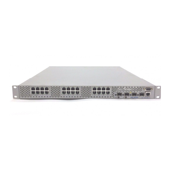
Physical Description The Application Switch series has two variants that are identified with an E or a DC at the end of the model name. The E variant is an enhanced version which is built to conform with the European Union Environmental Directive (EUED) for Restriction of Hazardous Substances (RoHS) . - Page 11 Figure 2 Application Switch 2216 Figure 3 Application Switch 2424 Figure 4 Application Switch 2424-SSL Note: The Application Switch 2424 and 2424-SSL are identical in appearance except for the model name appearing on the front panel (refer to Figure 3...
-
Page 12: Side Panel
The rear panel of AC powered Application Switches have a power supply connector and ventilation holes as illustrated in Figure Figure 6 Rear Panel of AC Powered Application Switch Refer to “AC Power Installation Procedure” on page 24 for instructions on connecting power to AC powered switches. - Page 13 Procedure” on page 25 for the DC power installation procedure. Figure 7 Rear Panel of DC Powered Application Switch Ports The following sections identify the port configurations for Application Switch 2000 and 3000 series. Application Switch 2000 Series Table 3 displays the number (and numbering) of Fast Ethernet and SFP GBIC ports on the Application Switch 2000 series.
-
Page 14: Fast Ethernet Ports
The LC jack is used for connecting Gigabit Ethernet fiber optic segments. The SFP modules are not shipped with the product. SFP modules can be ordered from Nortel. Note: Application Switches support only LC connectors with the SPF GBICs. Do not use SPF GBICs with MT-RJ connectors. - Page 15 9 - 12 (1U) Single-Mode Ports The Application Switch 3408 has eight single-mode ports broken down in the following manner: • Four 10/100/1000BaseT ports (1, 2, 7, 8) with RJ-45 connectors. These ports are autonegotiating and support half or full duplex operation.
-
Page 16: Management Port
SPF GBICs with MT-RJ connectors. Dual-Mode Ports The Application Switch 3408 is equipped with four dual-mode ports (3, 4, 5, 6). These ports have two interfaces each: 1000 Mbps SFP GBIC and 10/100/1000Base-T Copper. When the 1000 Mbps SFP GBIC port is selected as the preferred link, it is fixed at 1000 Mbps, full-duplex with autonegotiation turned on. - Page 17 Note: The Management Port does not support MDI/MDI-X functionality. Use a crossover cable on the 10/100 Mbps Management Port if the device attached to the port is a computer. If the device is a switch, hub, or a router, use a straight-through cable. Nortel Application Switch Hardware Installation Guide...
-
Page 18: Console Port
Console Port connection. LEDs The Application Switch has two LEDs for each FE port embedded into the RJ-45 connectors. There is one LED for each SFP GBIC port, and two LEDs for the Management Port. The LEDs light up to indicate the various port connection conditions. - Page 19 On (Green) Power is On Power is Off On (Amber) A fan has failed and/or the internal temperature has exceeded the threshold. See “Troubleshooting” on page 35 for more information. The fans are functioning. Nortel Application Switch Hardware Installation Guide...
-
Page 20: Installing The Switch Hardware
Blinking (Green) Data is being processed Installing the Switch Hardware This section describes how to install the Application Switch and connect cables to the network ports, the management port, and the console port. Package Contents Caution: This Product contains a Lithium Battery. Batteries are not customer replaceable parts. -
Page 21: Installation Preparation
When mounting this device in a rack, do not stack units directly on top of one another in the rack. Each unit must be secured to the rack with appropriate mounting brackets. Mounting brackets are not designed to support multiple units. Nortel Application Switch Hardware Installation Guide... -
Page 22: Installing The Switch
Connect the two mounting brackets to the switch using the supplied screws. Mounting brackets can be attached at mid-mount position or faceplate mount depending upon the required configuration. Figure 12 Mounting Brackets for E and DC variants of the Nortel Application Switch 315396-F... - Page 23 Figure 13 Mounting Brackets for Nortel Application Switch Install the switch as shown in Figure 14 using the appropriate screws for the rack-mount system (four 10-32, 12-24, M5X.8-6H, or M6X1-6H type screws). Figure 14 Rack-Mounted Application Switch 2424 Nortel Application Switch Hardware Installation Guide...
- Page 24 Connecting cables, power cord, AC adaptors shipped with the equipment or specified by Nortel to be used with the equipment. If you use any other equipment, it may cause "failures, malfunctioning or fire". According to the Denan regulation, power cords shipped with this equipment must not be used with any other equipment.
- Page 25 Install the crimped ring terminal over the chassis earth-ground terminal post. • Tighten the 6-32 nut to secure the ring terminal into place. Note: The switch must be connected to a protective earthing terminal in accordance with the National Electrical Code (NEC) article 250-160. Nortel Application Switch Hardware Installation Guide...
- Page 26 Connect the DC earth-ground lead prepared in Step 3 to the earth-ground terminal on the DC power source. Remove the Lexan protective cover from the terminal block by loosening and removing the 6-32 screws and washers. The location and appearance of the Lexan protective cover is illustrated in Figure 7 on page Remove the two ring terminals that are attached to the exposed terminal block by removing the...
-
Page 27: Connecting Cables
Connecting Cables Network Ports Each network port on the Application Switch has either an RJ-45 jack for FE ports connecting at 10/100 Mbps, an RJ-45 jack for GE copper ports connecting at 10/100/1000 Mbps or an SFP fiber port connecting at 1000 Mbps. - Page 28 Rx & Tx pins of the link (the MDI/MDI-X functionality). If the auto-negotiate mode is disabled, a crossover cable must be used when connecting the Application Switch FE port to another switch. Use a straight through cable when connecting to an end station, such as a PC.
-
Page 29: Initial Configuration
Note: Only pins 2, 3, and 5 are active Initial Configuration An Application Switch is ready to perform basic switching functions without prior configuration. The extensive switch software—the Nortel Application Switch Operating System—included in the switch provides a variety of options for accessing and configuring the switch. Some of the more advanced features however require some administrative configuration before they can be used effectively. -
Page 30: Initial Configuration Of The Switch
Initial Configuration of the Switch The Application Switch has a Console Port, Management Port and network ports that can be used for installing software and configuring the switch. This section explains how to perform the initial configuration of the switch using these ports. -
Page 31: Establishing A Telnet Connection
IP address. Establishing an SSH Connection Although a remote network administrator can manage the configuration of an Application Switch through Telnet, this method does not provide a secure connection. The SSH (Secure Shell) protocol enables secure remote login and communication not provided by Telnet. As a secure alternative to using Telnet to manage switch configuration, SSH ensures that all data sent over the network is encrypted and secure. - Page 32 Table 11 illustrates the initial screen for the Application Switch 2208, 2216, 2224, and 2424. Table 11 Application Switch 2208, 2216,2424 and 3408 initial screen display Enter password: System Information at 22:03:21 Mon May 8, 2006...
- Page 33 Table 12 illustrates the initial screen for the Application Switch 2424-SSL. Table 12 Application Switch 2424-SSL initial screen display Enter password: System Information at 22:58:31 Mon May 8, 2006 Time zone: No timezone configured (GMT offset 0:00) Alteon Application Switch 2424-SSL Switch is up 0 days, 0 hours, 57 minutes and 54 seconds.
-
Page 34: Using The Management Port
CD supplied as part of the documentation kit provided with the unit. Upgrading the Software The Application Switch is provided with software installed and configured with factory default settings. For more information about upgrading the switch software, refer to the Command Reference contained on the CD supplied as part of the documentation kit provided with the unit. -
Page 35: Troubleshooting
For more information on the serial upgrade procedure, refer to the Command Reference contained on the CD supplied as part of the documentation kit provided with the unit. Nortel Application Switch Hardware Installation Guide... - Page 36 If any fan stops Temperature exceeds appears on the during switch operation, threshold screen. contact Nortel Networks customer support. These messages are also appended to the output from the • Remember that units in a command.
-
Page 37: Switch Specifications
Switch Specifications The following sections outline the specifications of the units in the Application Switch 2000 and 3000 Series. Supported Standards Units in the Application Switch 2000 and 3000 Series support the standards listed below: • Spanning Tree Protocol (IEEE 802.1d) •... -
Page 38: Port Specifications
Port Specifications Table 14 lists the specifications of the physical ports found on units in the Application Switch 2000 and 3000 Series. Table 14 Port Specifications Port Connector Media Maximum Distance 10BaseT RJ-45 UTP Cat. 3, 4, or 5 100 meters (325 feet) -
Page 39: Power Requirements
512 BTU/hour thermal dissipation.) Typical power consumption 115 Watts at 25 degrees Celsius Environment Specifications Table 18 lists the environmental specifications for units in the Application Switch 2000 and 3000 Series. Table 18 Environmental Specifications Condition Operating Specifications Storage Specifications... -
Page 40: Mechanical Specifications
0.2g (3 to 200 Hz) (Sweep Rate = 1 octave/minute) (Sweep Rate = 1 octave/minute) Mechanical Specifications Table 19 lists the mechanical specifications of units in the Application Switch 2000 and 3000 Series. Table 19 Mechanical Specifications Unpackaged Operation Requirements... - Page 41 Certifications Table 20 lists the certification compliance of the Application Switch 2000 and 3000 Series. Table 20 Certifications Category Compliance EMC (Electromagnetic Requirements) CISPR 22, Class A and CISPR24 (International) FCC PArt 15, Subpart B, Class A (USA) ICES-003, Class A (Canada)
-
Page 42: Translations Of The Safety Messages
Translations of the Safety Messages This section provides translations of the Caution, Danger, and Warning messages that appear within this document. Caution: This device is a Class A product. In a domestic environment, this device can cause radio interference, in which case the user may be required to take appropriate measures. - Page 43 Attenzione: se il dispositivo viene installato in un rack, non impilare le unità direttamente una sull’altra. Ogni unità deve essere fissata al rack con le staffe di montaggio appropriate. Le staffe di montaggio non sono state progettate per supportare più unità. Nortel Application Switch Hardware Installation Guide...
- Page 44 Danger: Use only power cords that have a grounding path. Without a proper ground, a person who touches the switch is in danger of receiving an electrical shock. Lack of a grounding path to the switch may result in excessive emissions. Vorsicht: Verwenden Sie nur Netzkabel mit Schutzerdung.
- Page 45 Non guardare mai direttamente le fibre ottiche o le porte di collegamento. Tenere in considerazione il fatto che i cavi a fibre ottiche sono collegati a una sorgente luminosa. Nortel Application Switch Hardware Installation Guide...
- Page 46 315396-F...
- Page 47 Ne démontez pas ou ne rechargez pas. Cuidado: Este produto contem uma bateria do lítio. As baterias não são peças substituíveis do cliente. Podem explodir se mishandled. Não disponha da bateria no fogo. Não desmonte nem não recarregue. Nortel Application Switch Hardware Installation Guide...
- Page 48 315396-F...