Sign In
Upload
Manuals
Brands
YASKAWA Manuals
DC Drives
H6B1A028
YASKAWA H6B1A028 DC Drive Bypass Manuals
Manuals and User Guides for YASKAWA H6B1A028 DC Drive Bypass. We have
1
YASKAWA H6B1A028 DC Drive Bypass manual available for free PDF download: Technical Reference
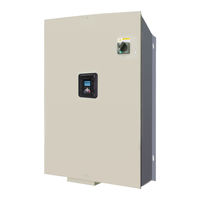
YASKAWA H6B1A028 Technical Reference (794 pages)
AC Drive Bypass for HVAC Fan and Pump Applications
Brand:
YASKAWA
| Category:
DC Drives
| Size: 68.6 MB
Table of Contents
Table of Contents
3
Preface and General Precautions
13
Definitions
14
Product Description
14
Glossary
14
About Registered Trademarks
14
Using the Product Safely
16
Explanation of Signal Words
16
General Safety
16
Warning Labels
18
Cybersecurity
19
Warranty Information
20
Exclusion of Liability
20
Receiving
21
Section Safety
22
Catalog Code and Nameplate Check
23
Narrow Bypass Nameplate
23
Enclosed Bypass Nameplate
24
Drive Nameplate
25
How to Read Narrow Bypass Catalog Codes
25
How to Read Enclosed Bypass Catalog Codes
26
Bypass Enclosures
29
Features and Advantages of V/F Control Method
29
Mechanical Installation
31
Section Safety
32
Installation Environment
34
Installation Positions and Clearances
35
Narrow Bypass Installation Position and Clearances
35
Enclosed Bypass Installation Position and Clearances
36
Bypass Components
37
Bypass Component Names
38
Narrow Bypass Component Names
38
Enclosed Bypass Component Names
40
Moving the Bypass
42
Using the Mounting Rails to Move the Bypass
42
Removing/Reattaching Covers
44
Removing/Reattaching the Bypass Cover Using Procedure 1
44
Removing/Reattaching the Drive Cover Using Procedure a
46
Opening/Closing the Bypass Cover Using Procedure 2
48
Removing/Reattaching the Drive Cover Using Procedure a
50
Removing/Reattaching the Cover Using Procedure B
51
Exterior and Mounting Dimensions
54
B077
56
Vac Enclosed Models H6B1D002 to D169240 Vac Enclosed Models H6B1A002 to A154480 Vac Enclosed Models H6B1B001 to B156
57
Vac Enclosed Models H6B1D211, D273240 Vac Enclosed Models H6B1A192, A248480 Vac Enclosed Models H6B1B180 to B302
61
Knock-Out Hole Dimensions
66
B077
66
Electrical Installation
69
Section Safety
70
Wiring Diagrams
72
Main Circuit Wiring
79
Narrow Bypass Input and Output Power Wiring Connections
79
Enclosed Bypass Input and Output Power Wiring Connections
80
Factory Recommended Branch Circuit Protection
80
Wire Selection
81
Main Circuit Terminal and Motor Wiring
87
Protection of Main Circuit Terminals
89
Main Circuit Terminal Wiring Procedure
90
Narrow Bypass Main Circuit Terminal Block Wiring Procedure
90
Enclosed Bypass Main Circuit Terminal Block Wiring Procedure
91
Bypass PCB Control Circuit
93
Wiring the Bypass Control Circuit Terminal
97
Drive PCB Control Circuit
99
Wiring the Drive Control Circuit Terminal
104
Control I/O Connections
106
Set Sinking Mode/Sourcing Mode
106
Set Input Signals for MFAI Terminals A1 and A2
106
Set Output Signals for MFAO Terminals FM, am
107
Switch on Termination Resistor for RS-485 Communications
107
Connect the Bypass to a PC
109
External Interlock
110
Drive Wiring Protection
112
Installing a Ground Fault Circuit Interrupter (GFCI)
112
(Gfci)
112
Improve the Power Factor
113
Connecting an AC Reactor
113
Prevent Switching Surge
114
Motor Application Precautions
115
Precautions for Existing Standard Motors
115
Precautions for Specialized Motors
116
Notes on the Power Transmission Mechanism
116
Startup Procedure and Test Run
117
Keypad: Names and Functions
119
LCD Display
120
AUTO LED and HAND LED Indications
121
Keypad Mode and Menu Displays
123
Start-Up, Test Operation, and Rotation Check
125
Items to Check before You Energize the Bypass
125
Bypass Start-Up Procedure
126
Test Run and Rotation Check
127
Keypad Operation
131
Home Screen Display Selection
131
Show the Monitors
132
Set Custom Monitors
133
Show Custom Monitors
134
Set the Monitors to Show as a Bar Graph
135
Show Monitors as Bar Graphs
136
Set the Monitors to Show as Analog Gauges
136
Show Monitors as an Analog Gauge
137
Set Monitor Items to Show as a Trend Plot
138
Show Monitor Items as a Trend Plot
142
Change Parameter Settings
143
Examine User Custom Parameters
144
Save a Backup of Parameters
145
Write Backed-Up Parameters to the Bypass
146
Verify Keypad Parameters and Bypass Parameters
148
Delete Parameters Backed up to the Keypad
149
Checking Modified Parameters
150
Restore Modified Parameters to Defaults
152
Show Fault History
153
Auto-Tuning
154
Set the Keypad Language Display
156
Set the Date and Time
157
Disable the Initial Setup Screen
159
Start Data Logging
160
Configuring the Data Log Content
161
Set Backlight to Automatically Turn off
163
Show Information about the Bypass
165
Write Automatically Backed-Up Parameters to the Bypass
166
Automatic Parameter Settings Optimized for Specific Applications
167
Presets)
167
Auto-Tuning
169
Auto-Tuning for Induction Motors
169
Fine Tuning During Test Runs (Adjust the Control Function)
171
V/F Control
171
Parameter Details
173
A: Initialization Parameters
174
A1: Initialization
174
A2: User Parameters
186
B: Application
187
B1: Operation Mode Selection
187
B2: DC Injection Braking
196
B3: Speed Search
197
B4: Timer Function
206
B5: PID Control
208
B8: Energy Saving
225
C: Tuning
227
C1: Accel & Decel Time
227
C2: S-Curve Characteristics
228
C3: Slip Compensation
229
C4: Torque Compensation
230
C6: Carrier Frequency
231
D: References
233
D1: Frequency Reference
233
D2: Reference Limits
237
D3: Jump Frequency
238
D4: Frequency Ref Up/Down & Hold
240
D6: Field Weakening
241
D7: Offset Frequency
241
E: Motor Parameters
243
E1: V/F Pattern for Motor 1
243
E2: Motor Parameters
250
F: Options
253
F6, F7: Communication Options and Ethernet Options
253
H: Terminal Functions
260
H1: Digital Inputs
260
5.7 H: Terminal Functions
261
MFDI Setting Value
264
H2: Digital Outputs
274
H2 MFDO Parameters
276
MFDO Setting Values
280
H3: Analog Inputs
293
H3: MFAI Parameters
295
MFAI Setting Value
298
H4: Analog Outputs
303
H5: Memobus/Modbus Communication
306
H7: Virtual MFIO Selection
312
L: Protection Functions
317
L1: Motor Protection
317
L2: Power Loss Ride through
320
L3: Stall Prevention
322
L4: Speed Detection
328
L5: Fault Restart
330
L6: Torque Detection
336
L8: Drive Protection
341
L9: Drive Protection 2
346
N: Special Adjustment
347
N1: Hunting Prevention
347
N3: High Slip Braking (HSB) and Overexcitation Braking
348
N3: High Slip/Overexcite Braking
348
O: Keypad-Related Settings
352
O1: Keypad Display Selection
352
O1: Keypad Display
354
O2: Keypad Operation
362
O3: Copy Function
365
O4: Maintenance Mon Settings
366
O5: Log Function
369
S: Special Applications
375
S1: Dynamic Noise Control
375
S2: Sequence Run Timers
376
S2: Sequence Run Timers
377
S3: PI2 Control
385
S5: Hand/Off/Auto Operation
390
S6: Protection
395
T: Auto-Tuning
405
T0: Tuning Mode Selection
405
T1: Induction Motor Auto-Tuning
405
T: Motor Tuning
405
Y: Application Features
407
Y1: Application Basics
407
Y2: PID Sleep and Protection
412
Y4: Application Advanced
415
YA: Preset Setpoint
419
YC: Foldback Features
421
YF: PI Auxiliary Control
421
Z: Bypass Parameters
430
Z1: Bypass Control System
430
Z2: Bypass Control Input/Output
441
Z3: Bypass Control Serial Comm
452
Troubleshooting
455
Section Safety
456
Types of Faults, Minor Faults, Alarms, and Errors
458
Faults, Minor Faults, Alarms, and Error Codes Listed Alphabetically
459
Faults, Minor Faults, Alarms, and Error Codes Listed
459
Alphabetically
459
Faults, Minor Faults, Alarms, and Error Codes Listed by Decimal Value for Use
466
With Bacnet/Modbus
466
Faults
472
Minor Faults/Alarms
496
Parameter Setting Errors
509
Auto-Tuning Errors
513
Backup Function Operating Mode Display and Errors
516
Bypass Status Messages
517
Diagnosing and Resetting Faults
518
Fault and Power Loss Occur at the same Time
518
Fault Occurs Without Power Loss
518
Fault Reset
518
Troubleshooting Without Fault Display
520
Typical Problems
520
The Parameter Settings will Not Change
520
The Motor Does Not Rotate after Entering Run Command
521
The Motor Rotates in the Opposite Direction from the Run Command
522
The Motor Rotates in Only One Direction
522
The Motor Is too Hot
522
Ope02 Error Occurs When Decreasing the Motor Rated Current Setting
523
The Motor Stalls During Acceleration or Accel/Decel Time Is too Long
523
Command
524
There Is too Much Motor Oscillation and the Rotation Is Irregular
524
There Is Audible Noise from the Drive or Motor Cables When the Drive Is Energized
524
The Ground Fault Circuit Interrupter (GFCI) Trips During Run
524
Motor Rotation Causes Unexpected Audible Noise from Connected Machinery
524
Motor Rotation Causes Oscillation or Hunting
525
PID Output Fault
525
The Motor Rotates after the Drive Output Is Shut off
525
The Output Frequency Is Lower than the Frequency Reference
525
The Motor Is Making an Audible Noise
526
The Motor will Not Restart after a Loss of Power
526
Specifications
527
Section Safety
528
Narrow Model Specifications
529
Narrow Model Specifications
531
Enclosed Model Specifications
533
Enclosed Model Specifications
535
7.6 480 V Enclosed Model Specifications
537
Common Bypass Specifications
539
Drive Watt Loss
541
Drive Derating
543
Carrier Frequency Settings and Rated Current Values
543
Derating Depending on Ambient Temperature
544
Altitude Derating
546
Peripheral Devices and Options
548
Bypass Options
548
Option Installation Procedure
549
Periodic Inspection and Maintenance
553
Section Safety
554
Inspection
556
Recommended Daily Inspection
556
Recommended Periodic Inspection
556
Maintenance
559
Replace Drive Cooling Fans and Circulation Fans
561
Cooling Fans and Circulation Fans
561
Replace a Fan (Procedure A)
561
Replace a Fan (Procedure B)
566
Replace a Fan (Procedure C)
572
Replace a Fan (Procedure D)
577
Replace a Fan (Procedure E)
580
Replace the Keypad Battery
587
Storage Guidelines
589
Parameter List
591
Section Safety
592
How to Read the Parameter List
593
Terms that Identify Parameters
593
Parameter Groups
594
A: Initialization Parameters
595
A1: Initialization
595
A2: User Parameters
595
B: Application
598
C: Tuning
605
D: Reference Settings
607
E: Motor Parameters
609
F: Options
611
L: Protection Functions
633
N: Special Adjustment
640
O: Keypad-Related Settings
641
S: Special Applications
647
T: Motor Tuning
656
Y: Application Features
657
Z: Bypass Parameters
665
U: Monitors
672
9.19 Defaults by Bypass and Drive Model
688
Advertisement
Advertisement
Related Products
YASKAWA H6B1A022
YASKAWA H6B1A002
YASKAWA H6B1A003
YASKAWA H6B1A004
YASKAWA H6B1A006
YASKAWA H6B1A042
YASKAWA H6B1A054
YASKAWA H6B1A068
YASKAWA H6B1A080
YASKAWA H6B1A015
YASKAWA Categories
Controller
DC Drives
Servo Drives
Robotics
Inverter
More YASKAWA Manuals
Login
Sign In
OR
Sign in with Facebook
Sign in with Google
Upload manual
Upload from disk
Upload from URL