Sign In
Upload
Manuals
Brands
WAGO Manuals
I/O Systems
750-461
WAGO 750-461 Manuals
Manuals and User Guides for WAGO 750-461. We have
4
WAGO 750-461 manuals available for free PDF download: Manual
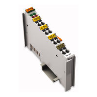
WAGO 750-461 Manual (64 pages)
2AI Pt100/RTD, 2-Channel Analog Input for Resistance Sensors for WAGO-I/O-SYSTEM 750
Brand:
WAGO
| Category:
Control Unit
| Size: 2.99 MB
Table of Contents
Deutsch
3
Table of Contents
3
1 Notes about this Documentation
5
Validity of this Documentation
5
Table 1: Variants
5
Copyright
6
Symbols
7
Number Notation
9
Font Conventions
9
Table 2: Number Notation
9
Table 3: Font Conventions
9
2 Important Notes
10
Legal Bases
10
Subject to Changes
10
Personnel Qualifications
10
Use of the 750 Series in Compliance with Underlying Provisions
10
Technical Condition of Specified Devices
11
Disposal
11
2.1.4.1.1 Electrical and Electronic Equipment
11
2.1.4.1.2 Packaging
12
Safety Advice (Precautions)
13
3 Device Description
15
View
16
Table 4: Legend for Figure "View
16
Connectors
17
Data Contacts/Local Bus
17
Power Jumper Contacts/Field Supply
18
Cage Clamp
18
Table 5: Legend for Figure „CAGE CLAMP ® Connectors
18
Display Elements
19
Table 6: Legend for Figure "Display Elements
19
Operating Elements
20
Schematic Diagram
20
Technical Data
21
Device Data
21
Power Supply
21
Communication
21
Table 7: Technical Data - Device
21
Table 8: Technical Data - Power Supply
21
Table 9: Technical Data - Power Supply
21
Table 10: Technical Data, Communication
21
Inputs
22
Table 11: Technical Data - Inputs (RTD Model 750-461)
22
Table 12: Technical Data - Inputs for 750-461/020-000 Model
22
Climatic Environmental Conditions
23
Connection Type
23
Table 13: Technical Data - Climatic Environmental Conditions
23
Table 14: Technical Data - Field Wiring
23
Table 15: Technical Data - Data Contacts
23
Approvals
24
Standards and Guidelines
26
4 Process Image
27
I/O Modules with Pt Resistance Sensors
27
Pt100
27
Table 16: I/O Modules with Pt Resistance Sensors
27
Pt1000
28
Table 17: Process Image, Pt100, with Wire Break Diagnostics
28
Table 18: Process Image, Pt1000, with Wire Break Diagnostics
28
Pt100 with Status Information for S5-FB250 in the Data Word
29
I/O Modules with ni Resistance Sensors
29
Table 19: Process Image, Pt100
29
Table 20: I/O Modules with ni Resistance Sensors
29
Ni100
30
Table 21: Process Image, Ni100, with Wire Break Diagnostics
30
Ni1000 TK6180
31
Table 22: Process Image, Ni1000 TK6180, with Wire Break Diagnostics
31
Ni1000 TK5000
32
Table 23: Process Image, Ni1000 TK5000, with Wire Break Diagnostics
32
I/O Modules for Resistance Measurement
33
Resistance Measurement 10 Ohm to 1.2 Kohm
33
Table 24: I/O Modules for Resistance Measurement
33
Table 25: Process Image (10 Ω to 1.2 Kω)
33
Resistance Measurement 10 Ohm to 5.0 Kohm
34
Configurable I/O Module 750-461/003-000
34
Table 26: Process Image (10 Ω to 5.0 Kω)
34
Table 27: Configurable I/O Module
34
Table 28: Setting Options for I/O Module 750-461/003-000
35
Table 29: I/O Module 750-461/003-000, Offset and Gain Values
35
I/O Module for NTC Resistance Sensors
36
Table 30: I/O Module 750-461/003-000, Input Fields for Hardware Matching
36
Table 31: I/O Module for NTC Resistance Measurement
36
Table 32: Process Image for Version 750-461/020-000
36
5 Mounting
37
Mounting Sequence
37
Inserting and Removing Devices
38
Inserting the I/O Module
38
Removing the I/O Module
39
6 Connect Devices
40
Connecting a Conductor to the CAGE CLAMP
40
Connection Examples
41
RTD, 2-Conductors
41
RTD, 3-Conductors
42
7 Use in Hazardous Environments
43
Marking Configuration Examples
44
Marking for Europe According to ATEX and Iecex
44
Table 33: Description of Marking Example According to ATEX and Iecex
45
Table 34: Description of Marking Example for Approved Ex I I/O Module According to ATEX and Iecex
47
Table 36: Description of Marking Example for Approved Ex I I/O Module
47
Marking for the United States of America (NEC) and Canada (CEC)
48
Table 35: Description of Marking Example According to NEC 500
48
Table 37: Description of Marking Example for Approved Ex I I/O Modules
49
Table 38: Description of Marking Example for Approved Ex I I/O Modules
50
Installation Regulations
51
Special Notes Regarding Explosion Protection
51
Special Notes Regarding ANSI/ISA Ex
53
8 Appendix
54
Configuration and Parameterization Using a GSD File with PROFIBUS DP and PROFINET IO
54
Configuration of the RS-232/RS-485 Interface
54
PROFIBUS DP Fieldbus Coupler/Controller 750-333(/0Xx-000)
54
750-833(/0Xx-000), PROFINET IO Fieldbus Coupler (750-370)
54
PROFINET IO Fieldbus Coupler 750-375(/025-000), 750-377(/025-000)
55
Table 39: Configuration PROFIBUS DP and PROFINET IO (750-370)
55
Table 40: Configuration PROFINET IO (750-375(/025-000), 750-377
55
Configuration of the RS-232/RS-485 Serial Interface
56
All PROFIBUS DP and PROFINET IO Fieldbus Couplers/Controllers
57
Table 41: Specific Module / Channel Parameters for 75X-652
58
PROFIBUS DP Fieldbus Coupler/Controller 750-333(/0Xx-000), 750-833(/0Xx-000), PROFINET IO Fieldbus Coupler 750-370
59
Table 42: General Module / Channel Parameters
59
PROFINET IO Fieldbus Coupler 750-375(/025-000), 750-377(/025-000)
60
English
61
Figure 1: View
16
Figure 2: Data Contacts
17
Figure 3: CAGE CLAMP ® Connectors
18
Figure 4: Display Elements
19
Figure 5: Schematic Diagram
20
Figure 6: Insert I/O Module (Example)
38
Figure 7: Snap the I/O Module into Place (Example)
38
Figure 8: Removing the I/O Module (Example)
39
Figure 9: Connecting a Conductor to a CAGE CLAMP
40
Figure 10: Example Connection 2 × RTD, 2-Wire
41
Figure 11: Example Connection 2 × RTD, 3-Wire
42
Figure 12: Marking Example According to ATEX and Iecex
44
Figure 13: Text Detail - Marking Example According to ATEX and Iecex
44
Figure 14: Marking Example for Approved Ex I I/O Module According to ATEX
46
Figure 15: Text Detail - Marking Example for Approved Ex I I/O Module According to ATEX and Iecex
46
Figure 16: Marking Example According to NEC
48
Figure 17: Text Detail - Marking Example According to NEC 500
48
Figure 18: Text Detail - Marking Example for Approved Ex I I/O Module
49
Figure 19: Text Detail - Marking Example for Approved Ex I I/O Module
49
Figure 20: Text Detail - Marking Example for Approved Ex I I/O Modules
50
Figure 21: Example of the PROFIBUS DP Fieldbus Coupler/Controller
56
Figure 22: Example of the 750-370 Fieldbus Coupler Configuration Dialog
56
Figure 23: Example of the 750-375(/025-000) and 750-377(/025-000) Fieldbus Coupler Configuration Dialog
57
List of Figures
61
List of Tables
62
Advertisement
WAGO 750-461 Manual (58 pages)
2AI Pt100/RTD 2-Channel Analog Input Module for Resistance Sensors
Brand:
WAGO
| Category:
I/O Systems
| Size: 2.64 MB
Table of Contents
Table of Contents
3
1 Notes about this Documentation
5
Validity of this Documentation
5
Table 1: Variants
5
Copyright
6
Symbols
7
Number Notation
9
Font Conventions
9
Table 2: Number Notation
9
Table 3: Font Conventions
9
2 Important Notes
10
Legal Bases
10
Subject to Changes
10
Personnel Qualifications
10
Use of the WAGO-I/O-SYSTEM 750 in Compliance with Underlying Provisions
10
Technical Condition of Specified Devices
11
Safety Advice (Precautions)
12
3 Device Description
14
View
15
Figure 1: View
15
Table 4: Legend for Figure "View
15
Connectors
16
Data Contacts/Internal Bus
16
Figure 2: Data Contacts
16
Power Jumper Contacts/Field Supply
17
Cage Clamp
17
Figure 3: CAGE CLAMP ® Connectors
17
Table 5: Legend for Figure „CAGE CLAMP ® Connectors
17
Display Elements
18
Figure 4: Display Elements
18
Table 6: Legend for Figure "Display Elements
18
Operating Elements
19
Schematic Diagram
19
Figure 5: Schematic Diagram
19
Technical Data
20
Device Data
20
Power Supply
20
Communication
20
Table 7: Technical Data - Device
20
Table 8: Technical Data - Power Supply
20
Table 9: Technical Data - Power Supply
20
Table 10: Technical Data, Communication
20
Inputs
21
Table 11: Technical Data - Inputs (RTD Model 750-461)
21
Table 12: Technical Data - Inputs for 750-461/020-000 Model
21
Climatic Environmental Conditions
22
Connection Type
22
Table 13: Technical Data - Climatic Environmental Conditions
22
Table 14: Technical Data - Field Wiring
22
Table 15: Technical Data - Data Contacts
22
Approvals
23
Standards and Guidelines
25
4 Process Image
26
I/O Modules with Pt Resistance Sensors
26
Pt100
26
Table 16: I/O Modules with Pt Resistance Sensors
26
Pt1000
27
Table 17: Process Image, Pt100, with Wire Break Diagnostics
27
Table 18: Process Image, Pt1000, with Wire Break Diagnostics
27
Pt100 with Status Information for S5-FB250 in the Data Word
28
Table 19: Process Image, Pt100
28
I/O Modules with ni Resistance Sensors
29
Ni100
29
Table 20: I/O Modules with ni Resistance Sensors
29
Table 21: Process Image, Ni100, with Wire Break Diagnostics
29
Ni1000 TK6180
30
Table 22: Process Image, Ni1000 TK6180, with Wire Break Diagnostics
30
Ni1000 TK5000
31
Table 23: Process Image, Ni1000 TK5000, with Wire Break Diagnostics
31
I/O Modules for Resistance Measurement
32
Resistance Measurement 10 Ohm to 1.2 Kohm
32
Table 24: I/O Modules for Resistance Measurement
32
Table 25: Process Image (10 Ω to 1.2 Kω)
32
Resistance Measurement 10 Ohm to 5.0 Kohm
33
Configurable I/O Module Fehler! keine Dokumentvariable Verfügbar./003-000
33
Table 26: Process Image (10 Ω to 5.0 Kω)
33
Table 27: Configurable I/O Module
33
Table 28: Setting Options for I/O Module 750-461/003-000
34
Table 29: I/O Module 750-461/003-000, Offset and Gain Values
34
I/O Module for NTC Resistance Sensors
35
Table 30: I/O Module 750-461/003-000, Input Fields for Hardware Matching
35
Table 31: I/O Module for NTC Resistance Measurement
35
Table 32: Process Image for Version 750-461/020-000
35
5 Mounting
36
Mounting Sequence
36
Inserting and Removing Devices
37
Inserting the I/O Module
37
Figure 6: Insert I/O Module (Example)
37
Figure 7: Snap the I/O Module into Place (Example)
37
Removing the I/O Module
38
Figure 8: Removing the I/O Module (Example)
38
6 Connect Devices
39
Connecting a Conductor to the CAGE CLAMP
39
Figure 9: Connecting a Conductor to a CAGE CLAMP
39
Connection Examples
40
RTD, 2-Conductors
40
RTD, 3-Conductors
40
Figure 10: Example Connection 2 × RTD, 2-Wire
40
Figure 11: Example Connection 2 × RTD, 3-Wire
40
7 Use in Hazardous Environments
41
Marking Configuration Examples
42
Marking for Europe According to ATEX and IEC-Ex
42
Figure 12: Side Marking Example for Approved I/O Modules According to ATEX and Iecex
42
Figure 13: Text Detail - Marking Example for Approved I/O Modules According to ATEX and Iecex
42
Table 33: Description of Marking Example for Approved I/O Modules According to ATEX and Iecex
43
Figure 14: Side Marking Example for Approved Ex I I/O Modules According to ATEX and Iecex
44
Figure 15: Text Detail - Marking Example for Approved Ex I I/O Modules According to ATEX and Iecex
44
Table 34: Description of Marking Example for Approved Ex I I/O Modules According to ATEX and Iecex
46
Marking for America According to NEC 500
47
Figure 16: Side Marking Example for I/O Modules According to NEC 500
47
Figure 17: Text Detail - Marking Example for Approved I/O Modules
47
Table 35: Description of Marking Example for Approved I/O Modules
47
Installation Regulations
48
Special Notes Regarding Explosion Protection
48
Special Notes Regarding ANSI/ISA Ex
50
8 Appendix
51
Configuration and Parameterization Using a GSD File with PROFIBUS DP and PROFINET IO
51
2AI RTD Configuration
51
PROFIBUS DP Fieldbus Couplers/Controllers 750-333(/0Xx-000), 750-833(/0Xx-000)
51
Table 36: PROFIBUS DP Configuration
51
PROFINET IO Fieldbus Couplers 750-375(/025-000), 750-377(/025-000)
52
2AI RTD Parameterization
52
Figure 18: Example of the PROFIBUS DP Fieldbus Couplers/Controllers Parameterization Dialog
52
Table 37: Configuration PROFINET IO
52
All PROFIBUS DP and PROFINET IO Fieldbus Couplers/Controllers
53
Figure 19: Example of the PROFINET IO Fieldbus Couplers Parameterization
53
Table 38: Specific Module/Channel Parameters for 75X-461/003-000
53
PROFIBUS DP Fieldbus Couplers/Controllers 750-333(/0Xx-000), 750-833(/0Xx-000)
54
Table 39: General Module/Channel Parameters
54
PROFINET IO Fieldbus Couplers 750-375(/025-000), 750-377(/025-000)
55
Table 40: General Module/Channel Parameters
55
List of Figures
56
List of Tables
57
WAGO 750-461 Manual (44 pages)
Brand:
WAGO
| Category:
I/O Systems
| Size: 1.28 MB
Table of Contents
Table of Contents
3
1 Important Notes
5
Legal Bases
5
Copyright
5
Personnel Qualifications
5
Use of the 750 Series in Compliance with Underlying Provisions
6
Technical Condition of Specified Devices
6
Standards and Guidelines for Operating the 750 Series
7
Symbols
8
Safety Information
9
Font Conventions
10
Number Notation
10
Scope
10
2 O Modules
12
Analog Input Modules
12
Overview Analog Input Modules for Rtd's 750-461 (/XXX-XXX)
12
750-461, (/XXX-XXX) [2 AI Pt100/ RTD]
13
Variations
13
View
14
Description
14
Display Elements
15
Schematic Diagram
16
Technical Data
17
Process Image
19
I/O Modules for Pt Resistance Sensors
19
I/O Modules for ni Resistance Sensors
23
Ni 1000 TK6180
24
I/O Modules for Resistance Measuring
25
Adjustable 750-461/003-000 Variation
26
750-461/020-000 [2 AI NTC 20Kohm]
28
View
28
Description
29
Display Elements
30
Schematic Diagram
30
Technical Data
31
Process Image
32
3 Use in Hazardous Environments
33
Identification
34
For Europe According to CENELEC and IEC
34
For America According to NEC 500
37
Installation Regulations
38
Advertisement
WAGO 750-461 Manual (28 pages)
Fieldbus Independent I/O Modules
Brand:
WAGO
| Category:
I/O Systems
| Size: 0.42 MB
Table of Contents
Table of Contents
3
1 Important Comments
4
Legal Principles
4
Copyright
4
Personnel Qualification
4
Intended Use
4
Symbols
5
Number Notation
5
Safety Notes
6
Scope
6
2 O Modules
7
Analog Input Modules
7
Overview Analog Input Modules for Rtd's 750-461, (/XXX-XXX)
7
750-461, (/XXX-XXX) [2 AI Pt100/ RTD]
8
View
8
Variations
8
Description
9
Display Elements
10
Schematic Diagram
11
Technical Data
12
Process Image
13
I/O Modules for Pt Resistance Sensors
14
Pt 100 with Status Information for S5-FB250 in Data Word
16
I/O Modules for ni Resistance Sensors
17
I/O Modules for Resistance Measuring
19
Adjustable 750-461/003-000 Variation
20
750-461/020-000 [2 AI NTC 20Kohm]
22
View
22
Description
23
Display Elements
24
Schematic Diagram
24
Technical Data
25
Process Image
26
Advertisement
Related Products
WAGO 750-461/000-003
WAGO 750-461/000-006
WAGO 750-461/000-200
WAGO 750-461/025-000
WAGO 750-461/000-004
WAGO 750-461/000-005
WAGO 750-461/000-009
WAGO 750-461/000-002
WAGO 750-461/000-007
WAGO 750-461/003-000
WAGO Categories
I/O Systems
Control Unit
Power Supply
Switch
Controller
More WAGO Manuals
Login
Sign In
OR
Sign in with Facebook
Sign in with Google
Upload manual
Upload from disk
Upload from URL