Sign In
Upload
Manuals
Brands
Sun Microsystems Manuals
Storage
SUN BLADE 150
Sun Microsystems SUN BLADE 150 Manuals
Manuals and User Guides for Sun Microsystems SUN BLADE 150. We have
4
Sun Microsystems SUN BLADE 150 manuals available for free PDF download: Service Manual, Getting Started Manual, Installation Manual
Sun Microsystems SUN BLADE 150 Service Manual (218 pages)
Brand:
Sun Microsystems
| Category:
Desktop
| Size: 4 MB
Table of Contents
Table of Contents
3
Table of Contents
17
Preface
21
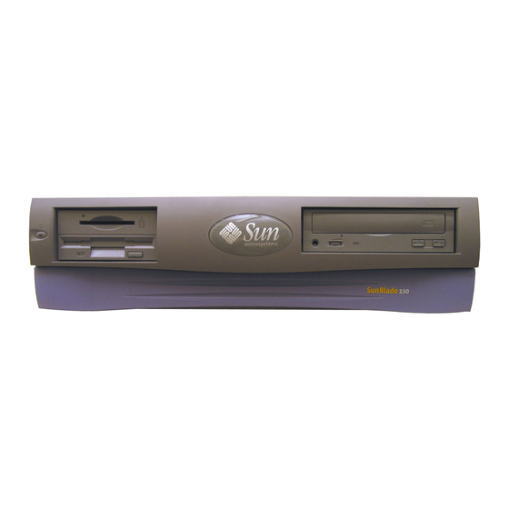
FIGURE 1-1 Sun Blade 150 System
28
1 Product Description
29
Product Overview
29
Supported Sun Monitors
30
System Description
30
TABLE 1-1 Supported Sun Monitors
30
TABLE 1-2 Sun Blade 150 System Physical Dimensions
30
FIGURE 1-2 Front Panel Overview
31
FIGURE 1-3 Back Panel Overview
31
Replaceable Components
32
TABLE 1-3 Back Panel Description and Connector Symbols
32
FIGURE 1-4 Sun Blade 150 System Replaceable Parts
33
TABLE 1-4 Sun Blade 150 Replaceable Components
34
2 Sunvts Overview
35
Sunvts Description
35
Sunvts Requirements
36
Sunvts References
36
3 Power-On Self-Test
37
POST Overview
37
How to Use POST
38
Pre-POST Preparation
38
FIGURE 3-1 Setting up a TIP Connection
39
Setting up a TIP Connection
39
Disconnecting a TIP Connection
40
Verifying the Baud Rate
40
Viewing the POST Menus
41
Initializing POST
41
Maximum and Minimum POST Levels
42
Diag-Level Variable Set to Max
42
Diag-Level Variable Set to Min
54
POST Progress and Error Reporting
61
Bypassing POST
63
Resetting Variables to Default Settings
63
Viewing the Default NVRAM Settings
64
Initializing Motherboard POST
64
4 Troubleshooting Procedures
65
Power-On Failure
65
Video Output Failure
66
Hard Drive, CD-ROM, or DVD-ROM Drive Failure
66
TABLE 4-1 Internal Drives Identification
67
Power Supply Test
68
DIMM Failure
69
Openboot PROM On-Board Diagnostics
69
Watch-Clock Diagnostic
69
Watch-Net and Watch-Net-All Diagnostics
70
Probe-IDE Diagnostic
71
Openboot Diagnostics
72
Openboot Diagnostics Menu Overview
72
Starting the Openboot Diagnostics Menu
73
Help Command
76
Openboot Diagnostics Help
76
Specific Openboot Diagnostics Tests
77
Test Command
77
Except Command
78
Test-All Command
78
Versions Command
79
What Command
79
Exit Command
80
Printenvs Command
80
Setenv Command
80
Error Reporting in Openboot Diagnostics
81
Exiting Openboot Diagnostics and Resetting the Openboot PROM Settings
81
5 Preparing for Component Removal and Replacement
83
Safety Requirements
83
Safety Symbols
84
Safety Precautions
84
Modification to Equipment
84
Electrostatic Discharge
85
Placement of a Sun Product
85
Power Cord Connection
85
Lithium Battery
86
Tools Required
86
Powering off the System
86
FIGURE 5-1 Front Panel Power Switch
87
Removing the System Cover
88
Attaching the Antistatic Wrist Strap
88
FIGURE 5-2 Removing the System Cover
88
FIGURE 5-3 Attaching the Wrist Strap to the Chassis
89
6 Removing and Replacing Major Subassemblies
91
Power Supply
91
Removing the Power Supply
91
FIGURE 6-1 Removing and Replacing the Power Supply
92
Replacing the Power Supply
92
Cable Assemblies
93
Removing the Diskette Drive Data Cable Assembly
93
FIGURE 6-2 Removing and Replacing the Diskette Drive Data Cable Assembly
94
Replacing the Diskette Drive Data Cable Assembly
94
FIGURE 6-3 Removing and Replacing the Diskette Drive Power Cable Assembly
95
Removing the Diskette Drive Power Cable Assembly
95
Removing the Primary IDE Cable Assembly
96
Replacing the Diskette Drive Power Cable Assembly
96
FIGURE 6-4 Removing and Replacing the Primary IDE Cable Assembly
97
Removing the Secondary IDE Cable Assembly
97
Replacing the Primary IDE Cable Assembly
97
FIGURE 6-5 Removing and Replacing the Secondary IDE Cable Assembly
98
Replacing the Secondary IDE Cable Assembly
98
FIGURE 6-6 Removing and Replacing the Smart Card Reader Cable Assembly
99
Removing the Smart Card Reader Cable Assembly
99
Removing the Power Switch/Led Assembly
100
Replacing the Smart Card Reader Cable Assembly
100
FIGURE 6-7 Removing the Front Bezel
101
FIGURE 6-8 Removing and Replacing the Power Switch/Led Assembly
102
Replacing the Power Switch/Led Assembly
102
Speaker Assembly
103
Removing the Speaker Assembly
103
FIGURE 6-9 Removing and Replacing the Speaker Assembly
104
Replacing the Speaker Assembly
105
Fan Assembly
105
Removing the Fan Assembly
105
FIGURE 6-10 Removing and Replacing the Fan Assembly
106
Replacing the Fan Assembly
106
7 Removing and Replacing Storage Devices
109
Diskette Drive
109
Removing the Diskette Drive
109
FIGURE 7-1 Removing and Replacing the Peripheral Assembly
110
FIGURE 7-2 Removing the Diskette Drive
111
Replacing the Diskette Drive
111
Smart Card Reader
112
Removing the Smart Card Reader
112
FIGURE 7-3 Removing and Replacing the Smart Card Reader
113
Replacing the Smart Card Reader
113
Hard Drives
114
Removing a Primary Hard Drive
114
FIGURE 7-4 Removing and Replacing a Primary Hard Drive
115
Replacing a Primary Hard Drive
115
Installing a Secondary Hard Drive
116
CD-ROM or DVD-ROM Drive
119
FIGURE 7-6 Secondary Hard Drive Cabling Configuration
119
Removing a CD-ROM or DVD-ROM Drive
119
FIGURE 7-7 Removing and Replacing a CD-ROM or DVD-ROM Drive
120
Replacing a CD-ROM or DVD-ROM Drive
120
8 Removing and Replacing the Motherboard and Related Components
123
Cpu
123
Removing the CPU
123
Replacing the CPU
125
FIGURE 8-2 JP3 Openboot PROM Jumper Settings for 650 Mhz and 550 Mhz Cpus
126
Nvram/Tod
127
Removing the NVRAM/TOD
127
FIGURE 8-3 Removing and Replacing the NVRAM/TOD
128
Replacing the NVRAM/TOD
128
Dimms
129
Removing a DIMM
129
FIGURE 8-4 DIMM Installation Order
130
FIGURE 8-5 Removing and Replacing a DIMM
131
Replacing a DIMM
131
PCI Card
132
Removing a PCI Card
132
FIGURE 8-6 Removing and Replacing a PCI Card
133
Replacing a PCI Card
133
Motherboard
134
Removing the Motherboard
134
FIGURE 8-7 Removing and Replacing the Motherboard
136
Replacing the Motherboard
136
FIGURE 8-8 JP1/JP2 Jumper Settings for the Flash PROM
137
TABLE 8-1 Flash PROM Jumper Settings
137
Riser Board
138
Removing the Riser Board
138
FIGURE 8-9 Removing and Replacing the Riser Board
139
Replacing the Riser Board
139
9 Finishing Component Replacement
141
Replacing the System Cover
141
Powering on the System
142
FIGURE 9-1 Replacing the System Cover
142
FIGURE 9-2 System Power Switch
142
10 Openboot Emergency Procedures
145
Openboot Emergency Procedures for Systems with Standard (Non-USB) Keyboards
145
Openboot Emergency Procedures for Systems with USB Keyboards
146
Stop-A Functionality
146
Stop-N Equivalent Functionality
146
Stop-F Functionality
147
Stop-D Functionality
148
Product Specifications and Reference Information
149
Physical Specifications
149
Electrical Specifications
150
Acoustic Specifications
150
Environmental Requirements
151
Clearance Requirements for Proper Cooling
151
Reference Information
152
CD Handling and Use
152
CD-ROM and DVD-ROM Jumper Settings
152
FIGURE A-1 Minimum Clearance for System Cooling
152
IDE Cabling Configuration
152
Cleaning the CD-ROM or DVD-ROM Drive
154
Ejecting a CD from the CD-ROM or DVD-ROM Drive
154
Handling and Storing Cds
154
Modem Setup Specifications
154
FIGURE A-3 External and Internal Serial Ports
155
Setting up the Modem
155
Changing the Serial Port Speed
156
Cable
157
Modem Recommendations
157
Modem Switch Settings (at Commands
157
Signal Descriptions
159
Power Supply Connectors
160
FIGURE B-1 Power Supply Connector J501 Pin Configuration
160
TABLE B-1 Power Supply Connector J501 Pin Assignments
160
FIGURE B-2 Secondary Power Supply Connector J505 Pin Configuration
161
TABLE B-2 Power Supply Connector J505 Pin Assignments
161
FIGURE B-3 USB Connector J17, J18 Pin Configuration
162
TABLE B-3 USB Connector J17, J18 Pin Assignments
162
Universal Serial Bus Connector
162
FIGURE B-4 IEEE 1394 Connector J20, J30 Pin Configuration
163
IEEE 1394 Connector
163
TABLE B-4 IEEE 1394 Connector J20, J30 Pin Assignments
163
FIGURE B-5 TPE Connector J19 Pin Configuration
164
TABLE B-5 TPE Connector J19 Pin Assignments
164
Twisted-Pair Ethernet Connector
164
External UTP-5 Cable Lengths
165
TPE Cable-Type Connectivity
165
FIGURE B-6 Serial Port Connector J36 Pin Configuration
166
Serial Port Connector
166
TABLE B-7 Serial Port Connector J36 Pin Assignments
166
FIGURE B-7 Riser Board Serial Port Pinouts (J13
167
TABLE B-8 Riser Board Serial Port Connector J13 Pin Assignments
167
FIGURE B-8 Accessing the Second Serial Port through a PCI Card Slot
168
FIGURE B-9 Serial and Video Port Connector Extensions
169
FIGURE B-10 Parallel Port Connector J9 Pin Configuration
170
Parallel Port Connector
170
TABLE B-9 Parallel Port Connector J9 Pin Assignments
170
Audio Connectors
172
Video Connector
173
Functional Description
175
System
175
Motherboard
177
Riser Board
178
Jumper Descriptions
179
Motherboard Components
180
Cpu
180
Ichip2 ASIC
181
Southbridge ASIC
181
Super I/O Functions
181
AC97 Compliant Audio Interface
183
PCI IDE Controller
183
ATI Rage XL ASIC
184
Ethernet
184
Graphics Memory
184
PCI Graphics
184
PCIO-2.X ASIC
184
Smbus Interface
184
Ieee 1394
185
Usb
185
PCI to PCI Bridge ASIC
185
Flash PROM
185
Smart Card Interface
186
Nvram/Tod
187
Reset Types
187
Clocking
187
Clock Generation
187
Openboot PROM Jumpers CPU Speed Selection
188
Power Control
189
Interrupting the System
189
Power Switch
189
Powering on the System
189
Forcing the System to Power-Off During Software Hang
190
On-Board VRM
190
Power-Off
190
Power-On
190
Power-On and Power-Off Circuitry
190
On-Board VRM Requirements
191
Optional Secondary Hard Drive
191
Power-On Beep
191
Power-On LED Control
191
Memory Architecture
192
SDRAM Address Multiplexing
194
Dimms
195
SDRAM DIMM Configuration
195
Speed and Timing
195
Address Mapping
196
Port Allocations
196
PCI Address Assignments
197
Energy Star
199
Interrupt Interface
199
Interrupts
199
Power
199
Usb
200
Special Procedures
201
Disabling Power Management
201
Setting the Default Console Display
202
Using USB Devices
205
USB Keyboard and Mouse
205
USB Power Management
205
Keyboards
205
Mouse Devices
206
Audio Devices
207
Hot Plugging
207
Printer Devices
207
Storage Devices
207
Advertisement
Sun Microsystems SUN BLADE 150 Getting Started Manual (74 pages)
Brand:
Sun Microsystems
| Category:
Storage
| Size: 1 MB
Table of Contents
Table of Contents
3
Preface
11
How this Book Is Organized
11
Safety and Compliance Information
12
Using UNIX Commands
13
Typographic Conventions
14
Shell Prompts
14
Accessing Sun Documentation Online
15
Sun Welcomes Your Comments
15
1 Setting up the Sun Blade 150 Workstation
17
Planning the Installation Process
18
Unpacking the Workstation
20
FIGURE 1-2 Unpacking the Workstation
20
FIGURE 1-3 Front Panel Overview
21
Front Panel Overview
21
Back Panel Overview
22
Figure
22
FIGURE 1-4 Back Panel Overview
22
Table
22
TABLE 1-1 Back Panel Description and Connector Symbols
22
FIGURE 1-5 Video and Serial Port Extenders
23
Table
23
Cabling the Workstation
24
FIGURE 1-6 Cabling the Workstation
25
Powering on the Workstation
26
2 Setting up the Preinstalled Solaris Operating Environment Software
27
Planning the Installation Process for Solaris
28
Setting up Your Operating Environment
29
FIGURE 2-1 Navigational Flow Chart for Setting up Your Operating Environment
29
Power Management Features
31
TABLE 2-1 Information Needed to Set up the Solaris Desktop Operating Environment
31
Putting the Workstation into Low-Power Mode
32
FIGURE 2-2 Sun USB Type-6 Keyboard Power Switch and Power off Selection Menu
33
3 Getting Started with the Additional Preinstalled Software
35
Hardware and Software Documentation
36
Viewing Hardware Documentation in HTML
37
Viewing Hardware Documentation in PDF
37
Solaris Documentation
37
Solaris User Collection
37
Solaris System Administrator Collection
37
Viewing Answerbook2 Documentation
38
Staroffice
38
Getting Started with Staroffice
39
XMCD
40
Adobe Acrobat Reader
40
Getting Started with Acrobat Reader
40
Apache Server
41
Getting Started with Apache Server
41
Perl
41
Getting Started with Perl
41
Development Tools for the Java Platform
42
Java Media Framework
42
Showme TV
43
Getting Started with Showme TV
43
Caldera Graphics Cameleolight
43
Getting Started with Cameleolight
44
Netscape Communicator
44
Getting Started with Netscape Communicator
45
Solstice Disksuite
45
Getting Started with Solstice Disksuite
45
Sun Opengl for Solaris
46
Getting Started with Opengl
46
PC File Viewer
46
Getting Started with PC File Viewer
47
PC Launcher
47
Getting Started with PC Launcher
47
Sunforum
48
Getting Started with Sunforum
48
Restoring Preinstalled Software
48
Restoring Preinstalled Software
49
4 Installing Optional Workstation Hardware
51
Preparing for Installation
52
Powering off the Workstation
52
FIGURE 4-1 Power Switch and Power Indicator LED Location
53
Removing Power to the Workstation
54
Powering off External Workstation Hardware
55
Disconnecting External Workstation Hardware
55
FIGURE 4-2 Disconnecting External Devices from the Workstation
56
Removing the Workstation Cover
57
FIGURE 4-3 Removing Workstation Cover
57
Attaching an Antistatic Wrist Strap
58
FIGURE 4-4 Attaching the Antistatic Wrist Strap
58
Installing Optional Internal Hardware
59
Workstation Internal Layout
59
FIGURE 4-5 Workstation Internal Layout (Top View with Cover Removed)
59
Installing Dimms
60
TABLE 4-1 Workstation Internal Layout
60
FIGURE 4-6 DIMM Installation Order (Top View of Workstation with Cover Removed)
61
Installing a PCI Card or Graphics Accelerator
62
FIGURE 4-8 Installing a PCI Card or Graphics Accelerator
63
Installing a CD-ROM or DVD-ROM Drive
64
FIGURE 4-9 PCI Card Guide
64
FIGURE 4-10 Installing a CD-ROM or DVD-ROM Drive
65
Installing a Second Hard Drive
66
FIGURE 4-11 Installing a Secondary Hard Drive
66
FIGURE 4-12 Reconnecting the Secondary Hard Drive Cables
68
Finishing Component Installation
69
For more Information
70
Troubleshooting and Technical Assistance
71
Troubleshooting the Workstation
71
TABLE A-1 Troubleshooting the Workstation
71
How to Get Technical Assistance
73
Sun Microsystems SUN BLADE 150 Installation Manual (20 pages)
CD-ROM, DVD-ROM, and Hard Drive
Brand:
Sun Microsystems
| Category:
Storage
| Size: 1 MB
Table of Contents
Installation Guide
1
Table of Contents
3
Sun Blade 150 CD-ROM, DVD-ROM, and Hard Drive Installation
5
Required Tools
5
Preparing to Replace Components
6
Powering off the System
6
Removing the System Cover
7
Attaching the Antistatic Wrist Strap
8
Removing a Primary Hard Drive
9
Replacing a Primary Hard Drive
11
Installing a Secondary Hard Drive
12
Removing a CD-ROM or DVD-ROM Drive
15
Replacing a CD-ROM or DVD-ROM Drive
16
Finishing Component Replacement
17
Powering on the System
18
Hard Drive Mirroring
18
Hard Drive Mirroring Configuration
19
Required Software and Patches
19
CD or DVD Handling and Use
19
Inserting a CD or DVD into the Drive
19
Ejecting a CD or DVD
20
Advertisement
Sun Microsystems SUN BLADE 150 Installation Manual (19 pages)
Brand:
Sun Microsystems
| Category:
Desktop
| Size: 0 MB
Table of Contents
Verifying the Current DIMM Configuration
3
Supported DIMM Configurations
4
Preparing for Installation
4
Powering off the System
4
Removing the System Cover
5
Attaching an Antistatic Wrist Strap
6
Installing the Dimms
8
Finishing Component Installation
12
Accessing Sun Blade 150 Documentation
15
Contacting Sun Technical Support
15
Sun Welcomes Your Comments
15
Advertisement
Related Products
Sun Microsystems Blade 6000
Sun Microsystems Sun StorageTek 5800
Sun Microsystems Sun StorEdge 5210 NAS
Sun Microsystems Sun StorEdge 5310 NAS
Sun Microsystems Sun Fire V1280
Sun Microsystems Sun StorEdge A1000
Sun Microsystems Sun StorEdge D1000
Sun Microsystems Sun StorageTek T9840D
Sun Microsystems Sun Storage J4200
Sun Microsystems Sun Storage J4400
Sun Microsystems Categories
Server
Storage
Desktop
Computer Hardware
Adapter
More Sun Microsystems Manuals
Login
Sign In
OR
Sign in with Facebook
Sign in with Google
Upload manual
Upload from disk
Upload from URL