Sign In
Upload
Manuals
Brands
Siemens Manuals
Media Converter
SINAMICS G120XA
User Manuals: Siemens SINAMICS G120XA Converter
Manuals and User Guides for Siemens SINAMICS G120XA Converter. We have
2
Siemens SINAMICS G120XA Converter manuals available for free PDF download: Operating Instructions Manual
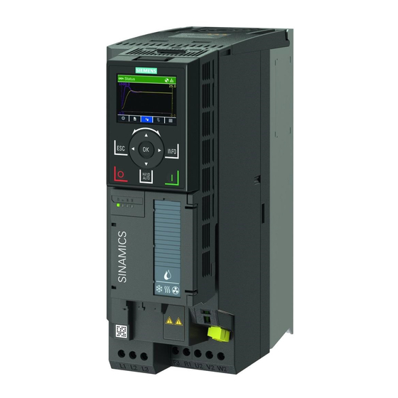
Siemens SINAMICS G120XA Operating Instructions Manual (919 pages)
Brand:
Siemens
| Category:
Media Converter
| Size: 13 MB
Table of Contents
Contents
3
Legal Information
4
Proper Use of Siemens Products
4
Qualified Personnel
4
Warning Notice System
4
Table of Contents
5
1 Fundamental Safety Instructions
13
General Safety Instructions
13
Equipment Damage Due to Electric Fields or Electrostatic Discharge
19
Warranty and Liability for Application Examples
20
Industrial Security
21
Residual Risks of Power Drive Systems
23
2 Description
25
About the Manual
25
What Is the Meaning of the Symbols in the Manual?
25
Who Requires the Operating Instructions and What For?
25
About the Converter
26
Use for the Intended Purpose
26
Use of Openssl
26
Use of Third-Party Products
26
Scope of Delivery
27
3-Phase 380 V AC to 440 V AC
28
Technical Data
28
Rating Plate
29
Directives and Standards
30
Relevant Directives and Standards
30
Standards that Are Not Relevant
31
Device Disposal
32
Recycling and Disposal
32
Optional Components
33
Overview
33
Article Number
34
Output Reactor
34
Requirements for Line Reactors
34
Sine-Wave Filter
36
Special Restrictions for Converter FSG
36
DV/Dt Filter Plus VPL
37
Operator Panel
37
Shield Connection Kit for the Power Module (FSD to FSG)
38
SINAMICS G120 Smart Access
38
Motors and Multi-Motor Drives that Can be Operated
39
Multi-Motor Operation
39
Siemens Motors that Can be Operated
39
Third-Party Motors that Can be Operated
39
3 Mounting
41
EMC-Compliant Setup of the Machine or Plant
41
EMC Zones
41
Inside the Control Cabinet
41
Control Cabinet Assembly
42
Measures Required for Several Control Cabinets
42
Control Cabinet
42
Cables
43
Cables with a High Level of Interference
43
Cables with a Low Level of Interference
43
Cable Routing Inside the Cabinet
44
Routing Converter Cables Inside and Outside a Control Cabinet
44
Routing Cables Outside the Control Cabinet
45
Requirements Relating to Shielded Cables
45
Electromechanical Components
45
Surge Voltage Protection Circuit
45
Power Losses and Air Cooling Requirements
46
Measures in Order to Ensure that the Components Are Adequately Cooled
46
Mounting the Converter
47
Basic Installation Rules
47
Requirements
47
Protection against the Spread of Fire
48
Mounting Position
48
Dimension Drawings and Drill Patterns
49
Dimensions and Clearance Distances (MM)
49
Drill Patterns (MM)
50
Mounting the Shield Connection Kit
51
Mounting the Shield Connection Kit for the Control Unit
51
FSH and FSJ
51
Mounting the Shield Connection Kit for the Power Module, FSA ... FSC
52
Mounting the Shield Connection Kit for the Power Module, FSD ... FSG
52
Procedure, FSD/FSE
53
Procedure, FSF
53
Procedure, FSG
54
Additional Mounting Instructions, FSD ... FSG
54
Hoisting Gear
54
Additional Mounting Instructions, FSH/FSJ
55
Lifting the Converter
55
Removing the Pallet
56
Lifting the Converter into the Cabinet
56
Mounting the Optional Components
57
4 Wiring
59
Line Supply and Motor
59
Permissible Line Supplies
59
TN System
59
Operating the Converter on a TN Line System
60
TT System
60
Function Description
61
Converter Operated on a TT System
61
IT System
61
Operating the Converter on an IT System
62
Converter Operated on an IT System
62
Removing Functional Grounding of the Converter
62
Removing Screw for Functional Grounding, FSG
63
Disconnecting the Basic Interference Suppression Module, FSH/FSJ
63
Minimum Cross-Section of the Protective Conductor
64
Additional Requirements Placed on the Protective Conductor
65
Maximum Permissible Motor Cable Length
66
EMC Category According to en 61800‑3
66
Without EMC Category
67
Connecting the Converter and Converter Components
68
Connection Overview
68
Connecting Converters FSD ... FSG and Their Optional Components
69
Connecting Converters FSH/FSJ and Their Optional Components
69
Connecting Converters, FSA ... FSC
70
Connecting Inverters
70
Connecting Converters, FSD ... FSG
71
Additional Information When Connecting FSG Converters
72
Connections for the Line Supply and Motor
72
Connecting Converters, FSH/FSJ
73
Cable Cross-Sections and Screw Tightening Torques
74
Cable Lugs
75
Connecting the Cable Shields (FSA ... FSG Only)
76
Connecting the Cable Shields, FSA ... FSC
76
Connecting the Cable Shields, FSD ... FSG
77
Connecting the Motor to the Converter in a Star or Delta Connection
78
Operating the Motor in a Star Connection
78
Operating the Motor in a Delta Connection with 87 Hz Characteristic
78
Control Interfaces
79
Overview of the Interfaces
79
Interfaces at the Front of the Control Unit
79
Fieldbus Interface Allocation
80
Interfaces at the Lower Side of the Control Unit
80
Terminal Strips
81
Terminal Strips with Wiring Example
81
Additional Options for Wiring the Digital Inputs
81
Factory Interface Settings
83
Default Setting of the Interfaces
84
Terminal Strip X9 (FSH/FSJ Only)
99
Wiring the Terminal Strips
101
RS485 Interface for the Fieldbus
103
Wiring the Terminal Strip in Compliance with EMC
103
Maximum Cable Length
103
Commissioning Guidelines
105
Tools
106
Compliance with the General Data Protection Regulation
106
Preparing for Commissioning
107
Collecting Motor Data
107
Data for a Standard Induction Motor
107
Which Motor Is Connected to the Converter?
107
Data for a Synchronous Reluctance Motor
108
How Is the Motor Connected?
108
Forming DC Link Capacitors
109
Production Year and Month
109
Forming the DC Link Capacitors
109
Converter Factory Setting
110
Converter Interfaces
110
Switching the Motor on and off
110
Minimum and Maximum Speed
110
Operate the Motor in the Factory Setting
111
Quick Commissioning Using the BOP-2 Operator Panel
112
Fitting the BOP-2 to the Converter
112
Overview of Quick Commissioning
113
Start Quick Commissioning and Select the Application Class
114
Starting Quick Commissioning
114
Selecting an Application Class
115
Standard Drive Control
116
Ramp-Up and Ramp-Down Time of the Motor
117
Minimum and Maximum Motor Speed
117
Dynamic Drive Control
118
Motor Cooling
119
Ramp-Down Time after the OFF3 Command
119
Expert
120
Select the Appropriate Application
121
Select the Control Mode
121
Ramp-Down Time for the OFF3 Command
123
Complete Quick Commissioning
123
Identifying the Motor Data and Optimizing the Closed-Loop Control
124
Restoring the Factory Settings
126
Why Restore the Factory Settings?
126
Resetting to Factory Setting with the BOP-2 Operator Panel
126
Advertisement
Siemens SINAMICS G120XA Operating Instructions Manual (1236 pages)
Brand:
Siemens
| Category:
Media Converter
| Size: 30 MB
Table of Contents
Qualified Personnel
4
Disclaimer of Liability
4
Table of Contents
5
Fundamental Safety Instructions
17
General Safety Instructions
17
Equipment Damage Due to Electric Fields or Electrostatic Discharge
24
Warranty and Liability for Application Examples
25
Cybersecurity Information
26
Residual Risks of Power Drive Systems
27
Description
29
About the Manual
29
About the Converter
30
Intended Use
30
Use for the Intended Purpose
30
Openssl
30
Transferring Openoss License Terms to a PC
31
Scope of Delivery
32
Rating Plate
34
Directives and Standards
35
ID Link and Siemens Online Support
37
Device Disposal
38
Recycling and Disposal
38
Optional Components
39
Further Information
39
External Line Filter
39
Article Number
40
Line Harmonics Filter
40
Restrictions for Use
41
Overheating Protection
41
Short Circuit Protection
42
Line Reactor
42
Output Reactor
44
Sine-Wave Filter
46
DV/Dt Filter Plus VPL
49
Operator Panel
50
SINAMICS G120 Smart Access
50
Memory Card
51
Function Description
51
Shield Connection Kit for the Power Module (FSD to FSG)
51
SINAMICS FSG Adapter Set
52
Applicable Products
52
Dimensions (Unit: MM)
53
Cable Cross-Sections and Screw Tightening Torques
53
Installation
54
I/O Extension Module
55
Outline Dimensions
55
Interface Overview
57
Motors and Multi-Motor Drives that Can be Operated
61
Additional Information
62
Mounting
63
Power Losses and Air Cooling Requirements
63
Mounting the Converter
65
Basic Installation Rules
65
Mounting Position
67
Dimension Drawings and Drill Patterns
67
Mounting the Shield Connection Kit
69
Additional Mounting Instructions for FSD
72
Additional Mounting Instructions, FSD
72
Hoisting Gear
72
Additional Mounting Instructions, FSH/FSJ
73
Lifting the Converter
73
Mounting the Optional Components
75
Wiring
77
Line Supply and Motor
77
EMC-Compliant Setup of the Machine or Plant
77
Control Cabinet
78
Further Information
79
Cables
80
Electromechanical Components
82
Permissible Line Supplies
83
TN System
83
TT System
84
Function Description
84
IT System
85
Removing Functional Grounding of the Converter
85
Requirements for the Protective Conductor
87
Fault Protection for the Motor Circuit
89
Operation with Residual Current Protective Device (RCD)
89
Maximum Permissible Motor Cable Length
91
Connecting the Converter and Converter Components
93
Connection Overview
94
Available Options
94
Connecting Converters
95
Cable Cross-Sections and Screw Tightening Torques
99
Cable Lugs
100
Connecting the Cable Shields (FSA
101
Connecting the Copper Busbars (FSH Only)
103
Connecting the Motor to the Converter in a Star or Delta Connection
106
Function Description
106
Control Interfaces
107
Overview of the Interfaces
107
Terminal Strips
108
Terminals Strips of I/O Extension Module
110
Factory Interface Settings
111
Default Setting of the Interfaces (Macros)
112
Overview
112
Default Setting (Macro) 41: "Analog Control
114
Analog Input
114
Default Setting (Macro) 42: "PID Controller with Analog Control
116
Default Setting (Macro) 43: "2 Pumps with Analog Control
118
Default Setting (Macro) 44: "3 Pumps with Analog Setpoint
120
Default Setting (Macro) 45: "Fixed Setpoint Control
122
Default Setting (Macro) 47: "PID Controller with Internal Fixed Setpoint
124
Default Setting (Macro) 48: "2 Pumps and Internal Fixed Setpoint
126
Default Setting (Macro) 49: "3 Pumps and Internal Fixed Setpoint
128
Default Setting (Macro) 57: "PROFINET Control
130
Default Setting (Macro) 58: "MOP Control
132
Default Setting (Macro) 59: "Blank I/O
134
Terminal Strip X9 (FSH/FSJ Only)
135
Wiring the Terminal Strips
138
Fieldbus
139
Connecting to PROFINET and Ethernet
140
Communication Via PROFINET IO and Ethernet
140
Protocols Used
141
Connecting the PROFINET Cable to the Converter
143
What Do You Have to Set for Communication Via PROFINET
143
Device Name
143
Application Examples
144
Installing GSDML
144
Connect Converter to Ethernet/Ip
144
What Do You Need for Communication Via Ethernet/Ip
145
Commissioning
147
Commissioning Guidelines
147
Tools
148
Preparing for Commissioning
150
Collecting Motor Data
150
Precharing the Circuit (FSH/FSJ Only)
152
Forming DC Link Capacitors
153
Converter Factory Setting
153
Minimum and Maximum Speed
155
Quick Commissioning Using the BOP-2 Operator Panel
157
Fitting the BOP-2 to the Converter
157
Overview
158
Starting Quick Commissioning
159
Function Description
159
Selecting an Application Class
159
Standard Drive Control
161
Dynamic Drive Control
163
Expert
166
Identifying the Motor Data and Optimizing the Closed-Loop Control
171
Restoring the Factory Settings
173
Handling the BOP-2 Operator Panel
174
Switching the Motor on and off
175
Changing Parameter Values
176
Additional Information
176
Changing Indexed Parameters
177
Entering the Parameter Number Directly
178
Entering the Parameter Value Directly
179
Why Can a Parameter Value Not be Changed
180
Further Information
180
Series Commissioning
181
Upload of the Converter Settings
183
Upload from the Converter to the Memory Card
184
Automatic Upload
184
Manual Upload with BOP-2
185
Message for a Memory Card that Is Not Inserted
186
Safely Removing a Memory Card Using the BOP-2
187
Uploading to the BOP-2
188
More Options for the Upload
189
Protecting the Converter Settings
191
Write Protection
191
Know-How Protection
193
Extending the Exception List for Know-How Protection
196
Activating and Deactivating Know-How Protection
197
Further Information
198
Advanced Commissioning
199
Overview of the Converter Functions
199
Brief Description of the Parameters
201
Drive Control
202
Switching the Motor on and off
202
Sequence Control When Switching the Motor on and off
202
Factory Setting
204
Selecting the ON/OFF Functions
205
Function Diagram 2634 - Sequence Control - Missing Enable Signals, Line Contactor Control
207
Adapt the Default Setting of the Terminal Strips
208
Digital Inputs
209
Analog Input as Digital Input
210
Digital Outputs
211
Analog Inputs
213
Adjusting Characteristics for Analog Input
215
Setting the Deadband
216
Analog Outputs
217
Adjusting Characteristics for Analog Output
218
Function Diagram 2221 - Digital Inputs
220
Function Diagram 2256 - Analog Inputs as Digital Inputs
221
Function Diagram 2244 - Digital Outputs
222
Function Diagram 2251 - Analog Inputs 0 and 1
223
Function Diagram 2252 - Analog Input 2
224
Function Diagram 2270 - Analog Input 3
225
Function Diagram 2261 - Analog Outputs
226
Drive Control Via PROFINET
227
Receive Data and Send Data
227
Drive Control
228
Telegrams
228
Advertisement
Related Products
Siemens SINAMICS G12
Siemens SINAMICS G120C DP
Siemens SINAMICS G120C PN
Siemens SINAMICS G120X
Siemens SINAMICS G120 PM240P-2
Siemens SINAMICS G120XA PN
Siemens SINAMICS G150
Siemens SINAMICS G130
Siemens SINAMICS G110D 6SL3511-0PE27-5AM0
Siemens SINAMICS G110D 6SL3511-0PE24-0AM0
Siemens Categories
Industrial Equipment
Control Unit
Controller
Oven
Washer
More Siemens Manuals
Login
Sign In
OR
Sign in with Facebook
Sign in with Google
Upload manual
Upload from disk
Upload from URL