Sign In
Upload
Manuals
Brands
Planmeca Manuals
Medical Equipment
Compact I
Planmeca Compact I Manuals
Manuals and User Guides for Planmeca Compact I. We have
1
Planmeca Compact I manual available for free PDF download: Technical Manual
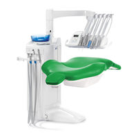
Planmeca Compact I Technical Manual (244 pages)
Brand:
Planmeca
| Category:
Medical Equipment
| Size: 7.78 MB
Table of Contents
Table of Contents
3
Chapter a GENERAL & TECHNICAL DATA
9
Warnings and Cautions
9
Manual Versions
10
Technical Specifications
11
List of Terms and Abbreviations in this Manual
14
Handling Precautions for Pcb's and Software Chips
15
Handling Printed Circuit Boards
15
Handling Software Flash-EPROM Chips
15
Emc Information
16
Chapter B CONTROL PANEL FUNCTIONS
21
Control Panel Overview
21
Normal User Functions
22
User Programming Mode
22
Programming Mode Function Details
24
Automatic Chair Positions
24
Instrument Spray Flow Rates
24
Chip Blow Flow Rates
25
Fibre Optic Light Intensity
26
Polymerization Light Exposure Time
26
Duration of the Bowl Rinsing and Duration of the Glass Filling
27
Intensity of the Operating Light
28
Duration of the Extra Function Relay Activation
28
Chapter C SERVICE MODE
29
General about the Service Mode
29
How to Enter Service Mode
30
How to Exit Service Mode and Store Settings
30
Navigating Among the Various Service Modes
31
Changing an Adjustable Setting in the Service Mode
31
Service Mode Functions Short-Form
32
Service Mode Detailed Description
45
MAIN Control System Related Service Modes
45
Instrument MUX Related Service Modes
50
Instrument Related Service Modes
54
Control Panel Related Service Modes
55
Suction Holder Related Service Modes
56
Foot Control Related Service Modes
57
Operating Light Related Service Modes
60
Patient Chair Related Service Modes
61
Separator/Suction System Related Service Modes
62
MCB CPU Direct I/O Related Service Modes (for Factory Use
63
Other Service Modes
65
Chapter D HELP & ERROR MESSAGES
79
Help Messages
79
General about Help Messages
79
Help Message Short-Form Table
79
Error Messages
84
General about Error Messages
84
Disabling/Enabling Error Messages
84
Error Message Short-Form Table
85
Detailed Description of Error Messages
88
General Error Messages
88
Power Supply Related Error Messages
89
Control Panel Related Error Messages
91
Instrument Related Error Messages
91
Instrument Multiplexer Related Error Messages
92
Suction Tube Holder (STH) Related Error Messages
95
Foot Control Related Error Messages
96
Operating Light Related Error Messages
97
Separator System Related
97
E58 Operating Light Bulb Burned out
97
E63 WMS Error
97
Patient Chair Related
98
Seat Position Potentiometer or Its Cable Is Faulty or Disconnected
98
Lift Motor or Its Position Pot Cable Has a Wrong Connection
98
Backrest Position Potentiometer or Its Cable Is Faulty or Disconnected
98
MAIN CPU Related Error Messages
99
Backrest Motor or Its Position Pot Cable Has a Wrong Connection
99
RAM Error
99
Error in Communicating with External Serial Device
99
Headrest Related Error Messages
100
Headrest Communication Error
100
Chapter E PREVENTIVE MAINTENANCE
101
Delivery Arms
101
Suction Arms
101
Instrument Console
102
Instruments
102
Foot Control
103
Cuspidor
103
Chair
104
Suction System
104
Clean Water System
105
Operating Light
105
Water Management System (Wms
106
Changing the Water Filter (00271003
108
Chapter F ADJUSTMENTS
111
Mechanical Adjustments
111
Adjusting Vertical Position of the OP Delivery Arm Column
111
Adjusting Friction of the OP Delivery Arm Joints
112
Adjusting Balance of the OP Delivery Arm
113
Adjusting Angle of the OP Delivery Arm Instrument Console
119
Adjusting the Side Delivery Arm Base Joint Friction
120
Adjusting the Friction of the Side Delivery Arm Joint
120
Adjusting the Side Delivery Arm Instrument Console Friction
121
Adjusting the Lifting Friction of the Side Delivery Arm
121
Adjusting the Tension of the Side Delivery Arm Gas Spring
123
Adjusting Friction of the Ergo Suction Arm
125
Adjusting Friction of the Adjustable Suction Arm
125
Removing Play of the Lifting Adapter
126
Adjusting the Instrument Arms
127
Electrical Adjustments
128
Calibrating Backrest Motor Position Sensor
128
Calibrating Lift Motor Position Sensor
130
Calibrating Motorized Headrest Motor Position Sensor
132
Rewiring Mains Voltage Selection Jumper
135
Pneumatical Adjustments
136
Adjusting Internal Water & Air Pressures
136
Adjusting Syringe Water and Air Flow Rates
137
Adjusting Coolants to the Instruments
137
Water Management System: Adjusting the Sensors
138
Preparations before Adjustment
138
Adjusting the Lower Sensor
140
Adjusting the Upper Sensor
140
Bleeding of the Spray Water System
141
Wms Operation
142
List of Abbreviations
142
WMS Operation, Normal Use
142
WMS Operation, WCS Use
145
Chapter G PARTS REPLACEMENT & REPAIR
151
Removing Covers
151
Upholsteries Replacement
153
Instrument Multiplexer Related
157
Preparations before Instrument Multiplexer Related Replacements
157
Replacing the Whole Multiplexer
157
Replacing One Multiplexer Block (Other than Syringe
161
Replacing Multiplexer Control Membrane
162
Replacing Instrument Control Valve
163
Replacing Instrument Multiplexer Proportional Valves
163
Suction System Related
164
Function of the PM Microvac II Separating Tank
164
Replacing the Whole PM Microvac II Separating Tank
167
Replacing Pressure Balancing Membrane
168
Replacing Intermediate And/Or Drain Membrane
168
Replacing Suction Closing Membrane
169
Electrical Parts Replacement
170
How to Replace/Upgrade the Software
170
Replacing Fuses
171
Replacing Main Control PCB
172
Replacing Instrument Multiplexer PCB
173
Replacing Control Panel PCB
174
Replacing Suction Sensor PCB
174
Replacing Transformer
175
Replacing Position Sensors
176
Motors Replacement
177
Replacing Backrest Motor
177
Replacing Chair Lift Motor
184
Valves & Filters Replacement
186
Decompressing Water and Air Pressures
186
Replacing the Whole Magnetic Valve/Pressure Regulator Assembly
186
Replacing Water and Air Filter/Regulator Assemblies
187
Replacing Water and Air Filters and the Water Regulator Plug
188
Replacing the Water / Air Regulator Membrane
189
Replacing Water or Air Main Valve Assembly
190
Cables & Tubes Replacement
191
Replacing OP Delivery Arm Cable
191
Other Parts Replacement
192
Detaching the Instrument Console from the OP Delivery Arm
192
Replacing OP Delivery Arm Gas Spring
193
Replacing the Whole OP Delivery Arm
194
Parts Replacement & Repair
194
Removing Foot Control Cover
195
Replacing Chair Control Springs
196
Replacing Foot Control PCB
197
Replacing Foot Control Cable
197
Replacing the Pedal Assembly (New Foot Control Model, from Serial Number 826740
198
Replacing Pedal Centering Spring
199
Adjustments
201
Centering Foot Control Pedal
201
Eliminating Sideways Play of the Foot Control Pedal
202
Adjusting Tension and Angle of the Foot Control Pedal
203
Adjusting Height of the Foot Control Pedal (Old Foot Control Model, Serial Number Smaller than 826740
204
Calibrating the Sector Plate and Adjusting the Angle of the Foot Control Pedal (New Foot Control Model, from Serial Number 826740
205
Calibrating Foot Control
209
Adjustments and Functional Check-Ups after Parts Replacements
211
Chapter I DIAGRAMS
214
Advertisement
Advertisement
Related Products
Planmeca Compact i Classic v2
Planmeca Chairside PlanScan
Planmeca Chairside PlanCAD Easy
Planmeca Chair
Planmeca Creo C5
Planmeca Creo
Planmeca 12370003
Planmeca 2D
Planmeca 2D S2
Planmeca Compact i Touch v2
Planmeca Categories
Medical Equipment
Dental equipment
Pet Care Product
Recording Equipment
Scanner
More Planmeca Manuals
Login
Sign In
OR
Sign in with Facebook
Sign in with Google
Upload manual
Upload from disk
Upload from URL