Sign In
Upload
Manuals
Brands
Omron Manuals
I/O Systems
SYSMAC C1000H
Omron SYSMAC C1000H Manuals
Manuals and User Guides for Omron SYSMAC C1000H. We have
4
Omron SYSMAC C1000H manuals available for free PDF download: Operation Manual, Installation Manual, System Manual
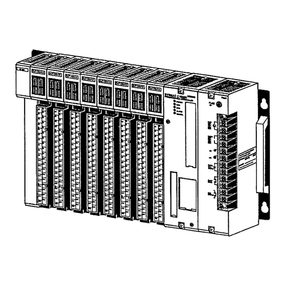
Omron SYSMAC C1000H Operation Manual (396 pages)
Brand:
Omron
| Category:
Controller
| Size: 2.6 MB
Table of Contents
Table of Contents
6
Section 1 Introduction
11
Overview
12
Relay Circuits: the Roots of PC Logic
12
PC Terminology
13
OMRON Product Terminology
14
Overview of PC Operation
14
Peripheral Devices
15
Available Manuals
17
Hardware Considerations
18
Indicators
19
PC Configuration
21
Section 3 Memory Areas
23
Memory Areas
23
Introduction
24
Data Area Structure
24
IR (Internal Relay)Area
24
IR (Internal Relay)Area
26
SR (Special Relay) Area
31
Link System Flags and Control Bits
32
Data Retention Control Bit
36
Output off Bit
37
FAL (Failure Alarm) Area
37
Low Battery Flag
37
Cycle Time Error Flag
37
I/O Verification Error Flag
37
First Cycle Flag
37
Clock Pulse Bits
37
Step Flag
38
Duplex System Flags
38
Instruction Execution Error Flag, er
38
AR (Auxiliary Relay) Area
39
Arithmetic Flags
39
3-5-1 SYSMAC LINK System Data Link Settings
41
3-5-2 Active Node Flags
41
SYSMAC LINK/SYSMAC NET Link System Service Time
42
Tracing Flags and Control Bits
42
File Memory Flags and Control Bits
42
On-Line Removal Bits
43
Power-Off Counter
43
DM (Data Memory) Area
44
Network Parameter Flags
44
Link Unit Mounted Flags
44
CPU-Mounting Device Flag
44
FALS-Generating Address
44
Cycle Time Indicators
44
HR (Holding Relay) Area
45
TC (Timer/Counter) Area
45
LR (Link Relay) Area
46
Program Memory
47
File Memory
47
Trace Memory
47
TR (Temporary Relay) Area
47
Section 4 Writing and Inputting the Program
48
Writing and Inputting the Program
48
Basic Procedure
49
Instruction Terminology
49
Basic Ladder Diagrams
50
Basic Terms
50
Mnemonic Code
51
Ladder Instructions
52
OUTPUT and OUTPUT NOT
55
The END Instruction
55
Logic Block Instructions
56
Coding Multiple Right-Hand Instructions
64
The Programming Console
65
The Keyboard
65
PC Modes
66
Preparation for Operation
68
The Display Message Switch
68
Entering the Password
68
Clearing Memory
69
Registering the I/O Table
71
Clearing Error Messages
73
Transferring the I/O Table
74
Changing the I/O Table
74
Changing I/O Units On-Line (C2000H Only)
76
Verifying the I/O Table
77
Reading the I/O Table
78
Inputting, Modifying, and Checking the Program
82
Setting and Reading from Program Memory Address
82
Entering or Editing Programs
83
Checking the Program
86
Displaying the Cycle Time
88
Program Searches
89
Inserting and Deleting Instructions
90
Branching Instruction Lines
93
Jumps
97
Controlling Bit Status
99
DIFFERENTIATE up and DIFFERENTIATE down
99
Keep
99
Work Bits (Internal Relays)
100
Self-Maintaining Bits (Seal)
100
Programming Precautions
102
Program Execution
104
Section 5 Instruction Set
105
Data Areas, Definer Values, and Flags
108
Instruction Format
108
Notation
108
Coding Right-Hand Instructions
110
Differentiated Instructions
110
Ladder Diagram Instructions
113
LOAD, LOAD NOT, AND, and NOT, OR, and or NOT
114
Bit Control Instructions
115
AND LOAD and or LOAD
115
OUTPUT and OUTPUT NOT - out and out NOT
115
DIFFERENTIATE up and DIFFERENTIATE down - DIFU(13) and DIFD(14)
116
Keep - Keep(11)
118
INTERLOCK and INTERLOCK CLEAR - IL(02) and ILC
119
INTERLOCK and INTERLOCK CLEAR - IL(02) and ILC(03)
119
JUMP and JUMP END - JMP(04) and JME
121
JUMP and JUMP END - JMP(04) and JME(05)
121
End - End(01)
122
Operation - Nop(00)
122
Timer and Counter Instructions
123
Timer - Tim
124
High-Speed Timer - Timh(15)
127
Counter - Cnt
128
Reversible Counter - Cntr(12)
131
Data Shifting
133
Shift Register - Sft(10)
133
Reversible Shift Register - Sftr(84)
135
Arithmetic Shift Left - Asl(25)
137
Arithmetic Shift Right - Asr(26)
138
Rotate Left - Rol(27)
138
Rotate Right - Ror(28)
139
One Digit Shift Left - Sld(74)
139
One Digit Shift Right - Srd(75)
140
Word Shift - Wsft(16)
140
Data Movement
141
Move - Mov(21)
141
Move Not - Mvn(22)
142
Block Set - Bset(71)
142
Block Transfer - Xfer(70)
144
Data Exchange - Xchg(73)
144
Single Word Distribute - Dist(80)
145
Data Collect - Coll(81)
145
Move Bit - Movb(82)
146
Move Digit - Movd(83)
147
Data Comparison
148
Compare - Cmp(20)
148
Block Compare - Bcmp(68)
151
Data Conversion
154
Bcd-To-Binary - bin(23)
154
Double Bcd-To-Double Binary - Binl(58)
154
Binary-To-Bcd - Bcd(24)
155
Double Binary-To-Double Bcd - Bcdl(59)
156
4-To-16 Decoder - Mlpx(76)
156
16-To-4 Encoder - Dmpx(77)
158
7-Segment Decoder - Sdec(78)
160
Ascii Convert - Asc(86)
163
BCD Calculations
164
Increment - Inc(38)
165
Decrement - Dec(39)
165
Set Carry - Stc(40)
165
Clear Carry - Clc(41)
165
Bcd Add - Add(30)
166
Double Bcd Add - Addl(54)
167
Bcd Subtract - Sub(31)
168
Double Bcd Subtract - Subl(55)
170
Bcd Multiply - Mul(32)
171
Double Bcd Multiply - Mull(56)
172
Bcd Divide - DIV(33)
173
Double Bcd Divide - Divl(57)
174
Floating Point Divide - Fdiv(79)
175
Square Root - Root(72)
178
Binary Calculations
180
Binary Add - Adb(50)
180
Binary Subtract - Sbb(51)
182
Binary Multiply - Mlb(52)
184
Logic Instructions
185
Binary Divide - Dvb(53)
185
Complement - Com(29)
185
And Word - Andw(34)
186
Or Word - Orw(35)
186
Exclusive or - Xorw(36)
187
Subroutines and Interrupt Control
188
Exclusive nor - Xnrw(37)
188
Overview
188
SUBROUTINE START and RETURN - SBN(92)/RET(93)
189
Subroutine Enter - Sbs(91)
189
Interrupt Control - Int(89)
191
Block Programming Instructions
196
Overview
196
BLOCK PROGRAM BEGIN - BPRG(96) and BLOCK PROGRAM END - BEND<01
196
SET - SET<07> and RESET - RSET<08
197
Block Branching-IF<02>, IF<02>NOT, ELSE<03>, and IEND<04
197
One Cycle and Wait - Wait<05
199
TIMER WAIT - TIMW<13> and HIGH-SPEED TIMER WAIT - TMHW<15
201
Counter Wait - Cntw<14
202
CONDITIONAL BLOCK EXIT - EXIT<06> and EXIT<06> NOT
203
Block Loop Control-LOOP<09>, LEND<10>, and LEND<10> NOT
203
BLOCK PROGRAM PAUSE - BPPS<11> and BLOCK PROGRAM RESTART - BPRS<12
204
Step Instructions
205
STEP DEFINE and STEP START-STEP(08)/SNXT(09)
205
Special Instructions
214
FAILURE ALARM - FAL(06) and SEVERE FAILURE ALARM - FALS(07)
214
Display Message - Msg(46)
215
Data Tracing (TRACE MEMORY SAMPLING - TRSM(45))
217
Watchdog Timer Refresh- Wdt(94)
217
I/O Refresh - Iorf(97)
217
File Memory Instructions
220
File Memory Read - Filr(42)
221
File Memory Write - Filw(43)
222
External Program Read - Filp(44)
222
Intelligent I/O Instructions
223
I/O Write - Writ(87)
224
I/O Read - Read(88)
224
Network Instructions
225
Network Send - Send(90)
225
Network Receive - Recv(98)
227
About SYSMAC NET Link/Sysmac LINK Operations
228
Section 6 Program Execution Timing
232
Program Execution Timing
232
Cycle Time
232
Calculating Cycle Time
232
Calculating Cycle Time
237
I/O Units Only
237
PC with Link Units
238
Instruction Execution Times
240
Instruction Execution Times
245
I/O Response Time
246
Section 7 Program Debugging and Execution
248
Program Debugging and Execution
248
Debugging
249
Displaying and Clearing Error Messages
249
Section 7
249
Entering Debug Mode
250
Address Execution
251
Debug Execution
253
Address Tracing
254
Address Trace Read
255
Monitoring Operation and Modifying Data
257
Bit/Word Monitor
257
Force Set/Reset
260
Hexadecimal/Bcd Data Modification
262
Hex/Ascii Display Change
263
Three-Word Monitor
264
Three-Word Data Modification
265
Binary Monitor
266
Binary Data Modification
267
Changing Timer/Counter SV
268
File Memory Operations
271
File Memory Clear
271
File Memory Write
272
File Memory Verify
275
File Memory Read
277
File Memory Edit
280
Program Backup and Restore Operations
281
Saving Program Memory Data
282
Restoring or Comparing Program Memory Data
283
Saving, Restoring, and Comparing DM Data
285
Error Processing
290
Alarm Indicators
291
Programmed Alarms and Error Messages
291
Reading and Clearing Errors and Messages
291
Error Messages
291
Error Flags
294
Troubleshooting
295
Standard Models
298
Programming Instructions
308
Programming Console Operations
339
Error and Arithmetic Flag Operation
352
Data Areas
356
I/O Assignment Records Sheets
360
Program Coding Sheet
365
Data Conversion Table
368
Extended ASCII
369
Glossary
370
Index
387
Revision History
393
Advertisement
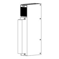
Omron SYSMAC C1000H Installation Manual (141 pages)
SYSMAC Series
Brand:
Omron
| Category:
Controller
| Size: 1.46 MB
Table of Contents
Table of Contents
6
Precautions
10
Intended Audience
11
General Precautions
11
Safety Precautions
11
Operating Environment Precautions
11
Application Precautions
12
Section 1
14
Introduction
14
What Is a Control System
15
The Role of the PC
16
Input Devices
17
Output Devices
17
How Does a PC Work
18
Available Manuals
20
Section 2
22
Description of All Components
22
CPU Rack
23
CPU Power Supply
26
I/O Backplane
28
Expansion I/O Backplane
29
I/O Power Supply
29
Duplex Unit (C2000H Duplex)
31
I/O Control Unit
31
I/O Interface Unit
31
File Memory Unit
32
Space Unit
32
I/O Remove Unit
32
I/O Units
33
Memory Packs
36
Section 3
38
Assembly
38
SECTION 3 Assembly
38
Mounting the Units
39
C2000H Duplex System
42
C2000H Simplex System
45
Memory Packs
45
System Configurations
47
Section 4
52
System Connections
52
SECTION 4 System Connections
52
Current Consumption
53
I/O Connections
56
Section 5
60
Installation Environment
60
SECTION 5 Installation Environment
60
Cooling
61
Mounting Requirements
61
Duct Work
63
Preventing Noise
64
Section 6
66
Power Considerations
66
Section 7
72
Safety Considerations
72
SECTION 7 Safety Considerations
72
Appendices
76
A Inspection and Maintenance
76
B Specifications
80
C Standard Models
122
Glossary
130
Index
134
Revision History
138
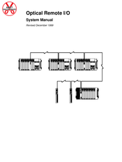
Omron SYSMAC C1000H System Manual (129 pages)
Optical Remote I/O
Brand:
Omron
| Category:
I/O Systems
| Size: 1.09 MB
Table of Contents
Table of Contents
8
Precautions
12
Intended Audience
12
General Precautions
12
Safety Precautions
12
Operating Environment Precautions
13
Application Precautions
13
Section 1
16
Introduction
16
Remote I/O Systems
17
Optical Remote I/O Systems
19
Section 2
21
System Design
21
Basic System
22
Multilevel Systems
24
C20, P-Type, and K-Type Systems
25
C120 Systems
25
C500 Systems
28
C1000H and C2000H Systems
31
C200H System
33
Combined Systems
36
Connection Precautions
38
Section 3
41
Operations
41
Block Diagrams
42
I/O Link Unit Operation
45
Unit Number and I/O Word Allocation
46
I/O Word Allocation Examples
50
Section 4
61
Unit Components and Switch Settings
61
Remote I/O Units
62
I/O Link Units
66
Optical I/O Units
68
Switch Settings
69
Section 5
75
System Installation
75
Dimensions
75
Optical Fiber Cable
75
Wiring
82
Section 6
85
I/O Response Times
85
Introduction
86
C500 Systems
86
C1000H and C2000H Systems
87
C200H Systems
88
Advertisement
Omron SYSMAC C1000H Operation Manual (86 pages)
Analog I/O Units
Brand:
Omron
| Category:
I/O Systems
| Size: 1.03 MB
Table of Contents
Sysmac C1000H/C2000H
2
Table of Contents
2
Section 1
4
System Design
4
Introduction
5
Basic Configuration
5
Example Configurations
6
Allocated Words
6
Section 2
8
Components and Switch Settings
8
AD101 Analog Input Modules
9
DA101 Analog Output Modules
12
Section 3 Installation
14
Section 3
14
Installation
14
SECTION 3 Installation
14
AD001 through AD005 Analog Input Modules
15
1--1 Dimensions
15
1--2 Wiring
16
AD006 and AD007 Analog Input Modules
18
2--1 Dimensions
18
2--2 Wiring
19
AD101 Analog Input Modules
21
3--1 Dimensions
21
3--2 Wiring
21
DA001 through DA005 Analog Output Modules
24
4--1 Dimensions
24
4--2 Wiring
25
DA101 Analog Output Modules
27
5--1 Dimensions
27
5--2 Wiring
27
Section 4 Operation
30
Section 4
30
Operation
30
SECTION 4 Operation
30
AD001 through AD005 Analog Input Modules
31
1--1 Block Diagram
31
1--2 A/D Conversion
31
1--3 IR Bit Allocations
32
AD006 and AD007 Analog Input Modules
33
2--1 Block Diagram
33
2--2 A/D Conversion
33
AD101 Analog Input Modules
34
2--3 IR Bit Allocations
34
3--1 Block Diagram
35
3--2 A/D Conversion
35
3--3 Operational Flow
36
3--4 Two-Word Operation
36
3--5 Four-Word Operation
42
DA001 through DA005 Analog Output Modules
43
4--1 Block Diagram
44
4--2 D/A Conversion
44
DA101 Analog Output Modules
46
4--3 IR Bit Allocations
46
5--1 Block Diagram
47
5--2 D/A Conversion
47
5--3 Operational Flow
48
5--4 IR Bit Allocations
49
Section 5 Programming Considerations
50
Section 5
50
Programming Considerations
50
SECTION 5 Programming Considerations
50
AD001 through AD005 Analog Input Modules
51
AD006 and AD007 Analog Input Modules
53
AD101 Analog Input Modules
55
3--1 Two-Word Operation
55
3--2 Four-Word Operation
62
DA001 through DA005 Analog Output Modules
72
DA101 Analog Output Modules
74
Appendix A Standard Models
76
Appendix B Specifications
78
Index
84
Revision History
86
Advertisement
Related Products
Omron C120
Omron CJ2M-CPU Series
Omron CJ1M-CPU21
Omron SYSMAC C200H-DA003
Omron SYSMAC C200H-DA004
omron CJ1W-DA041
OMRON SYSMAC CS1W-PRM21
Omron SYSMAC CS1W-PMV02
Omron SYSMAC CS1W-PTW01
Omron C500-AD101
Omron Categories
Blood Pressure Monitor
Controller
Accessories
Switch
Inverter
More Omron Manuals
Login
Sign In
OR
Sign in with Facebook
Sign in with Google
Upload manual
Upload from disk
Upload from URL