Omron Sysmac C1000H Operation Manual
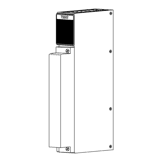
Rtd input module
Hide thumbs
Also See for Sysmac C1000H:
- Installation manual (141 pages) ,
- Operation manual (396 pages) ,
- System manual (129 pages)


Need help?
Do you have a question about the Sysmac C1000H and is the answer not in the manual?
Questions and answers