Sign In
Upload
Manuals
Brands
OMRON Manuals
Servo Drives
R88M-G series
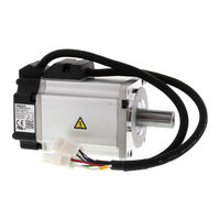
OMRON R88M-G series AC Servo Motor/Driver Manuals
Manuals and User Guides for OMRON R88M-G series AC Servo Motor/Driver. We have
5
OMRON R88M-G series AC Servo Motor/Driver manuals available for free PDF download: User Manual, Manual, System Configuration Manual
Omron R88M-G series User Manual (511 pages)
OMNUC G series AC SERVOMOTORS/SERVO DRIVES
Brand:
Omron
| Category:
Controller
| Size: 16 MB
Table of Contents
Intended Readers
3
Introduction
3
Explanation of Signal Words
6
Precautions for Safe Use
6
Storage and Transportation Precautions
8
Installation and Wiring Precautions
9
Maintenance and Inspection Precautions
10
Operation and Adjustment Precautions
10
Disposing of the Product
11
Warning Label Contents
11
Warning Label Position
11
Accessories Provided with Product
12
Items to Check When Unpacking
12
Understanding Servo Drive Model Numbers
13
Understanding Servomotor Model Numbers
14
Understanding Decelerator Model Numbers (Backlash = 3' Max.)
15
Understanding Decelerator Model Numbers (Backlash = 15' Max.)
16
About this Manual
17
Table of Contents
18
Table of Contents
19
Features and System Configuration
21
Overview of the G Series
22
Features of the G Series
22
Chapter 1 Features and System Configuration
23
System Configuration
23
Names of Parts and Functions
24
Servo Drive Part Names
24
Forward and Reverse Motor Rotation
25
Servo Drive Functions
25
R88D-Gta5L/-Gt01L/-Gt02L/-Gta5H/-Gt01H/-Gt02H/-Ht04H
26
System Block Diagrams
26
R88D-Gt04L/-Gt08H/-Gt10H/-Gt15H
27
R88D-Gt20H
28
R88D-Gt30H/Gt50H
29
R88D-Gt75H
30
Applicable Standards
31
EC Directives
31
UL and CSA Standards
31
Korean Radio Regulations (KC)
32
Semi F47
32
Chapter 2 Standard Models and Dimensions
33
Standard Models
34
Servo Drives
34
Servomotors
35
3,000-R/Min Servomotors
35
2,000-R/Min Servomotors
36
3,000-R/Min Flat Servomotors
36
1,000-R/Min Servomotors
37
3,000-R/Min Flat Servomotors and Servo Drives
38
3,000-R/Min Servomotors and Servo Drives
38
Servo Drive-Servomotor Combinations
38
1,000-R/Min Servomotors and Servo Drives
39
2,000-R/Min Servomotors and Servo Drives
39
Decelerators
40
Decelerators for 3,000-R/Min Servomotors
40
Decelerators for 2,000-R/Min Servomotors
42
Decelerators for 1,000-R/Min Servomotors
43
Decelerators for 3,000-R/Min Flat Servomotors
44
Decelerators for 3,000-R/Min Servomotors (Straight Shaft with Key)
45
Decelerators for 3,000-R/Min Flat Servomotors (Straight Shaft with Key)
46
Accessories and Cables
47
Encoder Cables (Standard Cables)
47
Servomotor Power Cables (Standard Cables)
48
Brake Cables (Standard Cables)
50
Encoder Cables (Robot Cables)
51
Servomotor Power Cables (Robot Cables)
52
Absolute Encoder Battery Cables
53
Brake Cables (Robot Cables)
53
Communications Cable
53
Connectors
53
Servo Relay Unit Cables for Servo Drives
54
Servo Relay Units (for CN1)
54
Servo Relay Unit Cables for Position Units
55
Control Cables
56
External Regeneration Resistors
56
Reactors
56
Absolute Encoder Backup Battery
57
Mounting Brackets (L Brackets for Rack Mounting)
57
External and Mounting Hole Dimensions
58
Servo Drives
58
Single-Phase 100 VAC: R88D-GTA5L/-GT01L (50 to 100 W)
58
Single-Phase 200 VAC: R88D-GT01H/-GT02H (50 to 200 W)
58
Front Panel Mounting (Using Mounting Brackets)
59
Single-Phase 100 VAC: R88D-GT02L (200 W)
60
Single-Phase 200 VAC: R88D-GT04H (400 W)
60
Single-Phase 100 VAC: R88D-GT04L (400 W)
61
Single-Phase/Three-Phase 200 VAC: R88D-GT08H (750 W)
61
Single-Phase/Three-Phase 200 VAC: R88D-GT10H/-GT15H (900 W to 1.5 Kw)
62
Three-Phase 200 VAC: R88D-GT20H (2 Kw)
63
Three-Phase 200 VAC: R88D-GT30H/-GT50H (2 to 5 Kw)
65
Three-Phase 200 VAC: R88D-GT75H (7.5 Kw)
67
3,000-R/Min Servomotors
68
Servomotors
68
3,000-R/Min Flat Servomotors
72
2,000-R/Min Servomotors
73
1,500-R/Min Servomotors
75
1,000-R/Min Servomotors
76
Parameter Unit Dimensions
78
R88A-PR02G Hand-Held Parameter Unit
78
Servomotor and Decelerator Combinations
79
Decelerator Dimensions
82
Outline Drawings
83
External Regeneration Resistor Dimensions
96
R88A-Rr08050S/-Rr080100S
96
R88A-Rr22047S1
96
R88A-Rr50020S
96
Reactor Dimensions
97
3G3Ax-Dl2002
97
3G3Ax-Dl2004
97
3G3Ax-Dl2007
98
3G3Ax-Dl2015
98
3G3Ax-Dl2022
99
3G3Ax-Al2025/-Al2055
99
3G3Ax-Al2110/-Al2220
100
Chapter 3 Specifications
101
Servo Drive Specifications
102
General Specifications
102
Characteristics
103
Servo Drives with 100-VAC Input Power
103
Servo Drives with Single-Phase 200-VAC Input Power
104
Servo Drives with Three-Phase 200-VAC Input Power
105
Protective Functions
106
Main Circuit and Servomotor Connections
107
Main Circuit Connector Specifications (CNA)
107
R88D-Gta5L/-Gt01L/-Gt02L/-Gt04Lr88D-Gt01H/-Gt02H/-Gt04H/-Gt08H/-Gt10H/-Gt15H
107
Servomotor Connector Specifications (CNB)
107
Main Circuit Terminal Block Specifications
108
R88D-Gt20H/-Gt30H/-Gt50H
108
Main Circuit Terminal Block Specifications (TB1)
109
Main Circuit Terminal Block Specifications (TB2)
109
R88D-Gt75H
109
Control I/O Connector Specifications (CN1)
110
Control I/O Signal Connections and External Signal Processing for Positioncontrol
110
Control I/O Signal Connections and External Signal Processing for Speedcontrol
111
Control I/O Signal Connections and External Signal Processing for Torquecontrol
112
CN1 Control Inputs
113
Control I/O Signals
113
CN1 Control Outputs
116
CN1 Connectors (50 Pins)
117
CN1 Pin Arrangement
117
Control Input Circuits
118
Position Command Pulse Input (Line Receiver Input)
118
Speed Command/Torque Command Input
118
Line Driver Input (500 Kpps Maximum)
119
Open-Collector Input
119
Position Command Pulse Input (Photocoupler Input)
119
Sensor Input
120
Sequence Input
120
Control Input Details
121
Functions
121
High-Speed Photocoupler Inputs
121
Command Pulse Timing for Photocoupler Inputs
122
Line-Receiver Inputs
123
Command Pulse Timing for Line-Receiver Inputs
124
Deviation Counter Reset Input (ECRST)
125
Reverse Drive Prohibit Input (NOT) and Forward Drive Prohibit Input (POT)
125
RUN Command Input (RUN)
125
Speed Command Input (REF) or Torque Command Input (TREF1)
125
Alarm Reset Input (RESET)
126
Control Mode Switch Input (TVSEL)
126
Pulse Prohibit Input (IPG) and Internally Set Speed Selection 1 (VSEL1)
126
Control Output Circuits
127
Phase-Z Output (Open-Collector Output)
127
Position Feedback Output
127
Sequence Output
127
Control Output Details
128
Control Output Sequence
128
Encoder Outputs (Phases A, B, and Z)
129
Alarm Output (/ALM)
130
Brake Interlock Output (BKIR)
130
Positioning Completed Output (INP) or Servomotor Rotation Speed Detectionoutput (TGON)
130
Servo Ready Output (READY)
130
Connectors for CN2 (6 Pins)
131
Encoder Connector Specifications (CN2)
131
Communications Connector Specifications (CN3A)
132
Connector for CN3A (8 Pins)
132
Connector for CN3B (8 Pins)
132
Parameter Unit Connector Specifications (CN3B)
132
General Specifications
133
Servomotor Specifications
133
Characteristics
134
Temperature Characteristics of the Servomotor and Mechanical System
146
Absolute Encoders
147
Encoder Specifications
147
Incremental Encoders
147
Decelerator Specifications
148
Standard Models and Specifications
148
Cable and Connector Specifications
158
Encoder Cable Specifications
158
Encoder Cables (Standard Cables)
158
Encoder Cables (Robot Cables)
161
Absolute Encoder Battery Cable Specifications
164
Power Cables for Servomotors Without Brakes (Standard Cables)
165
Servomotor Power Cable Specifications
165
Power Cables for Servomotors Without Brakes (Robot Cables)
170
Power Cables for Servomotors with Brakes (Standard Cables)
174
Power Cables for Servomotors with Brakes (Robot Cables)
177
Brake Cables (Standard Cables)
180
Brake Cables (Robot Cables)
182
Resistant to Bending of Robot Cables
183
Moving Bend Test
184
Communications Cable Specifications
185
Computer Monitor Cable
185
Connection Configuration and Dimensions
185
Wiring
185
Communications Cables
186
Connector Specifications
187
Control I/O Connector (R88A-CNU11C)
187
Encoder Connectors
187
Brake Cable Connector (R88A-CNG01B)
189
Power Cable Connector (R88A-CNG01A)
189
Control Cable Specifications
190
Motion Control Unit Cables (R88A-CPG@M@)
190
General-Purpose Control Cables (R88A-CPG@S)
193
Connector Terminal Block Cables (XW2Z-@J-B24)
195
Connector-Terminal Block Conversion Unit
197
XW2B-50G4 (M3 Screw Terminal Block)
197
XW2B-50G5 (M3.5 Screw Terminal Block)
198
XW2D-50G6 (M3 Screw Terminal Block)
199
Servo Relay Units and Cable Specifications
200
Xw2B-20J6-1B
200
Xw2B-40J6-2B
201
Xw2B-20J6-3B
202
Xw2B-20J6-8A
204
Xw2B-40J6-9A
206
Xw2B-80J7-12A
208
System Configuration Example for the FQM1
209
Terminal Block Connection
209
FQM1-MMA22 Signal Names
210
FQM1-MMP22 Signal Names
211
Wiring Example
212
Servo Drive Cable (XW2Z-@J-B25)
213
Servo Drive-Servo Relay Unit Cable Specifications
213
Servo Drive Cable (XW2Z-@J-B26)
214
Servo Drive Cable (XW2Z-@J-B27)
215
Servo Drive Cable (XW2Z-@J-B31)
216
Position Control Unit Cable (XW2Z-@J-A3)
217
Position Control Unit-Servo Relay Unit Cable Specifications
217
Position Control Unit Cable (XW2Z-@J-A6)
218
Position Control Unit Cable (XW2Z-@J-A7)
219
Position Control Unit Cable (XW2Z-@J-A10)
220
Position Control Unit Cable (XW2Z-@J-A11)
221
Position Control Unit Cable (XW2Z-@J-A14)
222
Position Control Unit Cable (XW2Z-@J-A15)
223
Position Control Unit Cable (XW2Z-@J-A18)
224
Position Control Unit Cable (XW2Z-@J-A19)
225
Position Control Unit Cable (XW2Z-@J-A33)
226
Position Control Unit Cable (XW2Z-@J-A28)
227
Position Control Unit Cable (XW2Z-@J-A30)
228
Position Control Unit Cable (XW2Z-@J-A31)
229
General Specifications
230
Parameter Unit Specifications
230
Performance Specifications
230
R88A-PR02G Hand-Held Parameter Unit
230
External Regeneration Resistor Specifications
231
R88A-Rr080100S
231
R88A-Rr08050S
231
R88A-Rr22047S1
231
External Regeneration Resistor Specifications
232
R88A-Rr50020S
232
Reactor Specifications
233
Chapter 4 System Design
235
Chapter 9 Appendix
235
Connection Examples
235
Installation Conditions
236
Operating Environment
236
Servo Drives
236
Space Around Drives
236
Keeping Foreign Objects out of Units
237
Connecting to Mechanical Systems
238
Impact and Load
238
Servomotors
238
Countermeasures against Oil
239
Radiator Plate Installation Conditions
239
Water and Drip Resistance
239
Oil Seal
240
Other Precautions
241
Decelerators
242
Installing Decelerators
242
Using Another Company's Decelerator (Reference Information)
245
Connecting Cables
246
System Configuration
246
Wiring
246
Selecting Connecting Cables
247
RS-485 Communications Cable
250
Servo Relay Units and Cables
250
Connector-Terminal Blocks and Cables
251
General-Purpose Control Cable and Control I/O Connector
251
Motion Control Unit Cable
251
Peripheral Device Connection Examples
252
R88D-Gt08H/-Gt10H/-Gt15H
253
Main Circuit and Servomotor Connections
256
Terminal Block Wire Sizes
259
Wire Sizes and Allowable Current (Reference)
260
Terminal Block Wiring Procedure
261
Wiring Conforming to EMC Directives
262
Wiring Method
262
Noise Filters for Power Supply Input
264
Control Panel Structure
265
Door Structure
266
No-Fuse Breakers (NFB)
267
Selecting Connection Components
267
Leakage Breakers
268
Surge Absorbers
269
Noise Filters for the Power Supply Input
270
Noise Filter for the Brake Power Supply
271
Radio Noise Filters and Emission Noise Prevention Clamp Cores
272
Contactors
274
Surge Suppressors
274
Improving Encoder Cable Noise Resistance
275
Improving Control I/O Signal Noise Resistance
276
Reactors to Reduce Harmonic Current
276
Selecting Other Parts for Noise Resistance
277
Calculating the Regenerative Energy
280
Horizontal Axis
280
Regenerative Energy Absorption
280
Vertical Axis
282
Amount of Internal Regeneration Absorption in Servo Drives
283
Servo Drive Regenerative Energy Absorption Capacity
283
Absorbing Regenerative Energy with an External Regeneration Resistor
284
Connecting an External Regeneration Resistor
284
External Regeneration Resistor
284
R88D-Gta5L/-Gt01L/-Gt02L/-Gt01H/-Gt02H/-Gt04H
284
R88D-Gt04L/-Gt08H/-Gt10H/-Gt15H/-Gt20H/-Gt30H/-Gt50H
285
Combining External Regeneration Resistors
286
Operating Functions
287
Parameters Requiring Settings
288
Position Control
288
Parameter Block Diagram for Position Control Mode
289
Related Functions
289
Speed Control
290
Parameter Block Diagram for Speed Control Mode
291
Internally Set Speed Control
292
Torque Control
295
Parameter Block Diagram for Torque Control Mode
297
Control Mode Selected at TVSEL (Control Mode Switch Input)
298
Switching the Control Mode
298
Operation Examples
299
Forward and Reverse Drive Prohibit
301
Encoder Dividing
302
Electronic Gear
303
Operating Conditions
306
Overrun Limit
306
Left Side Operation (Servo ON)
307
No Position Command Input (Servo ON)
307
Right Side Operation (Servo ON)
307
Brake Interlock
308
Precautions for Using the Electromagnetic Brake
308
Power Supply off Timing (When Servomotor Is Stopped)
309
RUN Command Timing (When Servomotor Is Stopped)
309
RUN Command, Errors, and Power Supply off Timing (When Servomotor Isrotating)
310
Alarm Clear (When Servo Is ON)
311
Gain Switching
312
Torque Limit
313
Torque Limit Settings
314
Soft Start
315
Position Command Filter
316
Speed Limit
317
Displaying Parameter Setting Mode
318
Setting and Checking Parameters
318
Setting the Parameter Number
318
User Parameters
318
Changing Parameter Settings
319
Displaying Parameter Settings
319
Saving the New Setting to Memory and Returning to the Parameter Number Display
319
Function Selection Parameters
320
Parameter Tables
320
Gain Parameters
325
Position Control Parameters
330
Speed and Torque Control Parameters
332
Sequence Parameters
334
Parameters Details
338
Function Selection Parameters (Pn00 to Pn0F)
338
Gain Parameters (Pn10 to Pn3D)
346
Position Control Parameters (Pn40 to Pn4E)
361
Speed and Torque Control Parameters (Pn50 and Higher)
368
Operation
381
Chapter 5 Operating Functions
382
Chapter 6 Operation
382
Operational Procedure
382
Preparing for Operation
383
Items to Check before Turning on the Power
383
Turning on Power
384
Checking Displays
384
Absolute Encoder Setup
386
Using the Parameter Unit
387
Names of Parts and Functions
387
Setting the Mode
388
Changing the Mode
388
Monitor Mode
389
Alarm History
393
Alarm Codes and Meanings
394
Reason for no Rotation Display (Front Panel Operation)
397
Parameter Setting Mode
398
Parameter Write Mode
400
Normal Mode Autotuning
401
Auxiliary Function Mode
402
Absolute Encoder Reset
404
Copy Mode
406
Copying from the Servo Drive to the Parameter Unit
406
Copying from the Parameter Unit to the Servo Drive
407
Trial Operation
409
Preparation for Trial Operation
409
Trial Operation in Position Control Mode
409
Checks before Trial Operation
409
Trial Operation in Speed Control Mode
410
Trial Operation in Torque Control Mode
410
Adjustment Functions
411
Chapter 7 Adjustment Functions
412
Gain Adjustment
412
Purpose of the Gain Adjustment
412
Gain Adjustment Methods
413
Gain Adjustment Procedure
414
Realtime Autotuning
415
Realtime Autotuning Setting Method
416
Operating Procedure
417
Fit Gain Function
418
Automatically Set Parameters
421
Adaptive Filter
422
Automatically Set Parameters
423
Normal Mode Autotuning
425
Normal Mode Autotuning Setting Method
426
Front Panel Operating Procedure
428
Precautions for Correct Use
429
Disabling the Automatic Gain Adjustment Function
430
Disabling Realtime Autotuning
430
Disabling the Adaptive Filter
431
Manual Tuning
432
Basic Settings
432
Position Control Mode Adjustment
433
Parameter Adjustment Values
434
Speed Control Mode Adjustment
435
Torque Control Mode Adjustment
436
Setting Speed Limit Values
436
Gain Switching Function
437
Setting Gain Switching Conditions
438
Speed Control Mode
439
Torque Control Mode
439
Machine Resonance Control
441
Torque Command Filter (Pn14, Pn1C)
441
Notch Filter
441
Automatic Gain Setting
443
Instantaneous Speed Observer
444
Damping Control
446
Troubleshooting
449
Chapter 8 Troubleshooting
450
Error Processing
450
Preliminary Checks When a Problem Occurs
450
Checking the Power Supply Voltage
450
Checking Whether an Alarm Has Occurred
450
Precautions When Troubleshooting
451
Replacing the Servomotor and Servo Drive
451
Alarm Table
452
Alarms
453
Troubleshooting
455
Error Diagnosis Using the Displayed Alarm Codes
455
Error Diagnosis Using the Operating Status
464
Overload Characteristics (Electronic Thermal Function)
469
Periodic Maintenance
470
Servomotor Service Life
470
Servo Drive Service Life
471
Replacing the Absolute Encoder Battery
472
Replacement Battery Model and Specifications
472
Mounting the Backup Battery
472
Battery Mounting Procedure
473
Appendix
475
Connection Examples
476
Connecting to SYSMAC CJ1W-NC133/233/433
476
Connecting to SYSMAC CJ1W-NC113/213/413
477
Connecting to SYSMAC CS1W-NC133/233/433
478
Connecting to SYSMAC CS1W-NC113/213/413 Orc200Hw-NC113/213/413
479
Connecting to a SYSMAC Motion Control Unit
480
Connecting to SYSMAC CP1H-Y@@DT-D
481
Connecting to SYSMAC CP1H-X@@DT-D/CP1L-@@@DT-D
482
Connecting to SYSMAC CJ1M
483
Connecting to a SYSMAC CS1W-HCP22-V1 Customizablecounter Unit
484
Connecting to a SYSMAC CS1W-HCA12/22-V1Customizable Counter Unit
485
Parameter Tables
486
Function Selection Parameters
486
Gain Parameters
491
Position Control Parameters
496
Speed and Torque Control Parameters
498
Sequence Parameters
500
Index
504
Revision History
508
Advertisement
Omron R88M-G series User Manual (460 pages)
AC SERVOMOTORS/SERVO DRIVES WITH BUILT-IN MECHATROLINK-II COMMUNICATIONS
Brand:
Omron
| Category:
Servo Drives
| Size: 6 MB
Table of Contents
Items to Check When Unpacking
13
About this Manual
19
Table of Contents
20
Overview
24
Features
24
System Configuration
25
Names of Parts and Functions
26
Servo Drive Part Names
26
Servo Drive Functions
27
Forward and Reverse Motor Rotation
27
System Block Diagrams
28
Applicable Standards
33
EC Directives
33
UL and CSA Standards
33
Korean Radio Regulations (KC)
34
Semi F47
34
Chapter 2 Standard Models and Dimensions
35
Standard Models
36
External and Mounting Hole Dimensions
60
Servo Drive Specifications
110
Servo Drive Specifications
116
Main Circuit and Servomotor Connector Specifications
116
Control I/O Connector Specifications (CN1)
119
Control Input Circuits
123
Control Output Circuits
123
Control Sequence Timing
124
Encoder Connector Specifications (CN2)
125
Parameter Unit Connector Specifications (CN3)
125
Servomotor Specifications
126
General Specifications
126
Encoder Specifications
140
Decelerator Specifications
141
Standard Models and Specifications
141
Cable and Connector Specifications
154
Encoder Cable Specifications
154
Absolute Encoder Battery Cable Specifications
160
Servomotor Power Cable Specifications
161
Communications Cable Specifications
181
Connector Specifications
182
MECHATROLINK-II Communications Cable Specifications
185
Control Cable Specifications
187
Parameter Unit Specifications
192
External Regeneration Resistor Specifications
193
Reactor Specifications
195
MECHATROLINK-II Repeater Specifications
196
Installation Conditions
200
Servo Drives
200
Servomotors
202
Decelerators
206
Wiring
212
Connecting Cables
212
Selecting Connecting Cables
213
Peripheral Device Connection Examples
217
Main Circuit and Servomotor Connector Specifications
221
Wiring Conforming to EMC Directives
227
Wiring Method
227
Selecting Connection Components
232
Conformity to IEC 61800-5-1
245
Regenerative Energy Absorption
247
Calculating the Regenerative Energy
247
Servo Drive Regenerative Energy Absorption Capacity
250
Absorbing Regenerative Energy with an External Regeneration Resistor
251
Connecting an External Regeneration Resistor
252
Position Control
256
Position Control
257
Speed Control
259
Speed Control
260
Torque Control
262
Torque Control
264
Forward and Reverse Drive Prohibit
265
Brake Interlock
266
Torque Limit
271
Torque Limit
272
Soft Start
273
Acceleration/Deceleration Time Settings
274
Moving Average Time
275
Electronic Gear
276
Speed Limit
277
Sequence Input Signals
278
Sequence Output Signals
280
Backlash Compensation
282
Overrun Protection
284
Gain Switching
286
Speed Feed-Forward
293
Torque Feed-Forward
294
Speed Feedback Filter Selection
295
P Control Switching
296
Torque Command Filter Time Constant
297
Notch Filter
298
Adaptive Filter
300
Instantaneous Speed Observer
303
Damping Control
305
Damping Control
306
User Parameters
310
Setting and Checking Parameters
310
Parameter Tables
316
Details on Important Parameters
341
Operational Procedure
354
Preparing for Operation
355
Items to Check before Turning on the Power
355
Turning on Power
357
Checking the Displays
358
Absolute Encoder Setup
359
Using the Parameter Unit
361
Names of Parts and Functions
361
Setting the Mode
362
Changing the Mode
362
Monitor Mode
363
Parameter Setting Mode
370
Parameter Write Mode
376
Normal Mode Autotuning
377
Auxiliary Function Mode
378
Copy Mode
381
Trial Operation
384
Preparation for Trial Operation
384
Trial Operation with CX-Drive
384
Gain Adjustment
386
Purpose of the Gain Adjustment
386
Gain Adjustment Methods
386
Gain Adjustment Procedure
387
Realtime Autotuning
388
Realtime Autotuning Setting Method
389
Machine Rigidity Setting Method
389
Normal Mode Autotuning
394
Manual Tuning
399
Chapter 8 Troubleshooting
407
Error Processing
408
Alarm Table
410
Troubleshooting
414
Overload Characteristics (Electronic Thermal Function)
428
Periodic Maintenance
429
Chapter 9 Appendix
433
Parameter Tables
434
Omron R88M-G series User Manual (328 pages)
SERVOMOTORS/SERVO DRIVES
Brand:
Omron
| Category:
DC Drives
| Size: 7 MB
Table of Contents
Table of Contents
16
Limitations of Liability
4
Application Considerations
5
Dimensions and Weights
5
Performance Data
6
Safety Precautions
7
About this Manual
15
Table of Contents
16
Chapter 1 Features and System Configuration
20
Overview
20
Overview of the SMARTSTEP 2 Series
20
Features of the SMARTSTEP 2 Series
20
System Configuration
21
Names of Parts and Functions
22
Servo Drive Part Names
22
Servo Drive Functions
23
System Block Diagrams
24
Applicable Standards
25
EC Directives
25
Ul/Cul Standards
25
Chapter 2 Standard Models and Dimensions
27
Standard Models
28
Standard Models
29
Parameter Unit
29
Servo Drive-Servomotor Combinations
29
Servo Drives
29
Servomotors
29
Decelerators
31
Accessories and Cables
35
Power Supply Cables
36
Connector-Terminal Block Conversion Units
39
Din Rail Mounting Unit
39
External and Mounted Dimensions
40
Servo Drives
40
Servomotors
42
Parameter Unit Dimensions
45
Decelerator Dimensions
46
External Regeneration Resistor Dimensions
54
Reactor Dimensions
55
DIN Rail Mounting Unit Dimensions
56
Chapter 3 Specifications
57
Servo Drive Specifications
58
Specifications
58
General Specifications
58
Characteristics
59
Control Specifications
59
Main Circuit and Servomotor Connector Specifications (CNA and CNB)
60
Control I/O Connector Specifications (CN1)
61
Control Input Circuits
65
Control Input Details
66
Alarm Reset Input
66
Control Output Circuits
69
Control Output Details
70
Alarm Output
70
Warning Output
71
Feedback Output
71
Encoder Connector Specifications (CN2)
72
Servomotor Specifications
73
General Specifications
73
Motor Rotation Directions
73
Characteristics
74
Torque and Rotation Speed Characteristics
78
Applicable Load Inertia
82
Encoder Specifications
82
Decelerator Specifications
83
Standard Models and Specifications
83
Cable and Connector Specifications
87
Encoder Cable Specifications
87
Robot Cables for Encoders
88
Servomotor Power Cable Specifications
89
Standard Cables for Brakes
91
Robot Cables for Brakes
92
Power Cable Specifications
94
Communications Cable Specifications
97
Connector Specifications
98
Encoder Connectors
100
Control Cable Specifications
102
General-Purpose Control Cables
102
Connector-Terminal Block Conversion Unit
105
Servo Relay Units and Cable Specifications
110
Servo Relay Units Specifications
110
System Configuration Example
117
Servo Drive-Servo Relay Unit Cable Specifications
120
Position Control Unit-Servo Relay Unit Cable Specifications
123
Parameter Unit Specifications
135
External Regeneration Resistors Specifications
136
Reactor Specifications
137
Chapter 4 System Design
139
Installation Conditions
140
Servo Drives
140
Operating Environment
142
Servomotors
142
Other Precautions
144
Oil Seal
144
Decelerators
145
Wiring
149
Connecting Cables
149
Selecting Connecting Cables
150
Peripheral Device Connection Examples
153
Main Circuit Wiring
155
Wiring Conforming to EMC Directives
157
Wiring Method
157
Unit Details
158
Control Panel Structure
159
Selecting Connection Components
161
Leakage Breakers
162
Surge Absorbers
163
Surge Suppressors
167
Noise Filters for Servomotor Output
170
Regenerative Energy Absorption
172
Calculating the Regenerative Energy
172
Absorbing Regenerative Energy with an External Regeneration Resistor
174
Servo Drive Regenerative Energy Absorption Capacity
174
Chapter 5 Operating Functions
177
Position Control
178
High-Response Position Control Vs. Advanced Position Control
178
Parameters Requiring Settings
178
Parameter Block Diagram for Position Control Mode
180
Internally Set Speed Control
181
Parameters Requiring Settings
181
Related Parameters
181
Operation
182
Selecting the Internally Set Speeds
182
Parameter Block Diagram for Internally Set Speed Control Mode
183
Forward and Reverse Drive Prohibit
184
Parameters Requiring Settings
184
Operation
184
Encoder Dividing
185
Parameters Requiring Setting
185
Operation
185
Electronic Gear
186
Parameters Requiring Settings
186
Operation
186
Related Parameter
187
Brake Interlock
188
Parameters Requiring Setting
188
Operation
188
Gain Switching
190
Parameters Requiring Setting
190
Related Parameters
191
Torque Limit
192
Parameters Requiring Setting
192
Related Parameters
192
Overrun Limit
193
Parameters Requiring Settings
193
Operation
193
User Parameters
194
Setting and Checking Parameters
194
Parameter List
197
Parameter Details
209
Chapter 6 Operation
239
Operational Procedure
240
Preparing for Operation
240
Preparing for Operation
241
Items to Check before Turning on the Power
241
Turning on Power
241
Checking Displays
242
Using the Parameter Unit
243
Names of Parts and Functions
243
Display When Power Is Turned on
244
Changing the Mode
245
Monitor Mode
246
Parameter Setting Mode
254
Parameter Write Mode
255
Autotuning Mode
256
Auxiliary Function Mode
257
Jog Operation
258
Copy Mode
259
Trial Operation
262
Preparation for Trial Operation
262
Chapter 7 Adjustment Functions
265
Gain Adjustment
265
Gain Adjustment
266
Purpose of the Gain Adjustment
266
Gain Adjustment Methods
266
Gain Adjustment Procedure
267
Realtime Autotuning
267
Realtime Autotuning
268
Realtime Autotuning Setting Method
268
Operating Procedures
269
Adaptive Filter
270
Automatically Set Parameters
271
Autotuning
272
Autotuning
273
Autotuning Setting Method
273
Automatically Set Parameters
276
Disabling the Automatic Gain Adjustment Function
278
Disabling Realtime Autotuning
278
Disabling the Adaptive Filter
279
Manual Tuning
280
Function Differences in Control Modes
280
Basic Adjustment Procedures
281
Gain Switching Function
284
Machine Resonance Control
286
Damping Control
288
Chapter 8 Troubleshooting
291
Error Processing
292
Preliminary Checks When a Problem Occurs
292
Precautions When Troubleshooting
293
Replacing the Servomotor and Servo Drive
293
Alarm Table
294
Alarm Indicator on the Servo Drive
294
Alarm List
295
Troubleshooting
296
Points to Check
296
Error Diagnosis Using the Displayed Alarm Codes
297
Error Diagnosis Using the Operating Status
303
Overload Characteristics (Electronic Thermal Function)
307
Overload Characteristics Graphs
307
Periodic Maintenance
308
Servomotor Service Life
308
Servo Drive Service Life
309
Revision History
325
Advertisement
OMRON R88M-G series Manual (18 pages)
G-SERIES SERVO SYSTEM
Brand:
OMRON
| Category:
Servo Drives
| Size: 2 MB
Table of Contents
System Configuration
4
Servo Drive Specifications
5
Servo Drive Part Names
6
Servo Drives
7
Servo Motor Specifications
9
Ratings and Specifications
9
Installation
13
Ordering Information
14
Encoder Cables
15
OMRON R88M-G series System Configuration Manual (9 pages)
G-Series servo motors
Brand:
OMRON
| Category:
Engine
| Size: 0 MB
Table of Contents
Type Designation
2
Servo Motor Specifications
3
Servo Motors
5
Ordering Information
7
Servo Motor
7
Servo Drive
7
Advertisement
Related Products
Omron R88M-GP20030H
Omron R88M-G40030T-BS2
Omron R88M-GP40030T-BS2-D
Omron R88M-G40030H-BS2-D
Omron R88M-GP40030H-S2-D
Omron R88M-GP20030H-BS2
Omron R88M-W40030T
Omron R88M-K10030H
Omron OMNUC R88M-U05030HA-BS1
Omron OMNUC R88M-U30030LA-BS1
OMRON Categories
Blood Pressure Monitor
Controller
Accessories
Switch
Inverter
More OMRON Manuals
Login
Sign In
OR
Sign in with Facebook
Sign in with Google
Upload manual
Upload from disk
Upload from URL