
Related Manuals for Omron R88D-GT series


Summary of Contents for Omron R88D-GT series
- Page 1 Cat. No. I562-E1-04 USER’S MANUAL OMNUC G SERIES R88M-G@ (AC Servomotors) R88D-GT@ (AC Servo Drives) AC SERVOMOTORS/SERVO DRIVES...
- Page 2 OMRON. No patent liability is assumed with respect to the use of the information contained herein. Moreover, because OMRON is constantly striving to improve its high-quality products, the information contained in this manual is subject to change without notice.
- Page 3 Introduction Introduction Thank you for choosing the OMNUC G Series. This User’s Manual describes installation/wiring methods and parameter setting procedures required for the operation of the OMNUC G Series as well as troubleshooting and inspection methods. Intended Readers This manual is intended for the following personnel. Those with knowledge of electrical systems (a qualified electrical engineer or the equivalent) as follows: •...
- Page 4 Omron’s exclusive warranty is that the Products will be free from defects in materials and workman- ship for a period of twelve months from the date of sale by Omron (or such other period expressed in writing by Omron). Omron disclaims all other warranties, express or implied.
- Page 5 Disclaimers Performance Data Data presented in Omron Company websites, catalogs and other materials is provided as a guide for the user in determining suitability and does not constitute a warranty. It may represent the result of Omron’s test conditions, and the user must correlate it to actual application requirements. Actual performance is subject to the Omron’s Warranty and Limitations of Liability.
- Page 6 Make sure that these protective covers and shields are put in place as specified before using the product. Consult your OMRON representative when using the product after a long period of storage. WARNING Always connect the frame ground terminals of the Servo Drive and the Servomotor to 100 Ω...
- Page 7 Precautions for Safe Use Installation, operation, maintenance, or inspection must be performed by authorized personnel. Not doing so may result in electric shock or injury. Wiring or inspection must not be performed for at least 15 minutes after turning OFF the power supply.
- Page 8 Precautions for Safe Use WARNING Do not place any flammable materials near the Servomotor, Servo Drive, or Regeneration Resistor. Doing so may result in fire. Mount the Servomotor, Servo Drive, and Regeneration Resistor on metal or other non- flammable materials. Failure to do so may result in fire.
- Page 9 Precautions for Safe Use Installation and Wiring Precautions Caution Do not step on or place a heavy object on the product. Doing so may result in injury. Do not cover the inlet or outlet ports and prevent any foreign objects from entering the product.
- Page 10 Precautions for Safe Use Operation and Adjustment Precautions Caution Confirm that no adverse effects will occur in the system before performing the test operation. Not doing so may result in equipment damage. Check the newly set parameters for proper operation before actually running them. Not doing so may result in equipment damage.
- Page 11 Precautions for Safe Use Warning Label Position Warning labels are located on the product as shown in the following illustration. Be sure to follow the instructions given there. Location of warning label (R88D-GT01H) Warning Label Contents Disposing of the Product •...
- Page 12 • No connectors or mounting screws are provided. They have to be prepared by the user. • Should you find any problems (missing parts, damage to the Servo Drive, etc.), please contact your local sales representative or OMRON sales office. Connector for main circuit...
- Page 13 Items to Check When Unpacking Understanding Servo Drive Model Numbers The model number provides information such as the Servo Drive type, the applicable Servomotor capacity, and the power supply voltage. R88D-GT01H OMNUC G-Series Servo Drive Drive Type T : Three-mode type Applicable Servomotor Capacity A5 : 50 W 01 : 100 W...
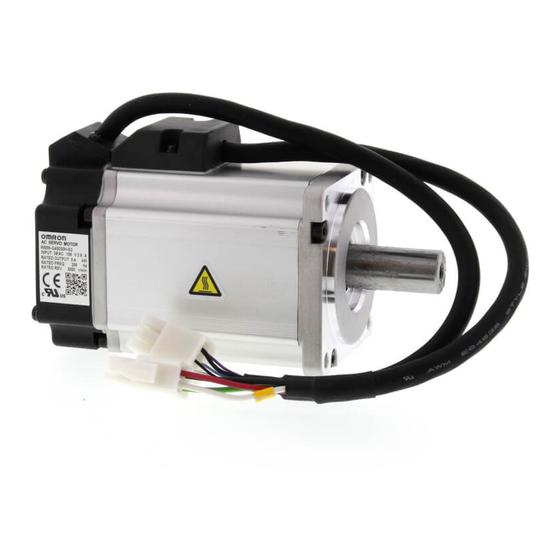
- Page 14 Items to Check When Unpacking Understanding Servomotor Model Numbers R88M-GP10030H-BOS2 G-Series Servomotor Motor Type Blank: Cylinder type Flat type Servomotor Capacity 050: 50 W 100: 100 W 200: 200 W 400: 400 W 750: 750 W 900: 900 W 1K0: 1 kW 1K5:...
- Page 15 Items to Check When Unpacking Understanding Decelerator Model Numbers (Backlash = 3' Max.) R88G-HPG14A05100PBJ Decelerator for G-Series Servomotors Backlash = 3’ Max. Flange Size Number :@40 :@60 :@90 :@120 :@170 :@230 Gear Ratio :1/5 :1/9 (only frame number 11A) :1/11 (except frame number 65A) :1/12 (only frame number 65A) :1/20 (only frame number 65A)
- Page 16 Items to Check When Unpacking Understanding Decelerator Model Numbers (Backlash = 15' Max.) R88G-VRSF09B100PCJ Decelerator for G-Series Servomotors Backlash = 15’ Max. Gear Ratio :1/5 :1/9 :1/15 :1/25 Flange Size Number :@52 :@78 :@98 Applicable Servomotor Capacity : 50 W :100 W :200 W :400 W...
- Page 17 LED displays and the countermeasures, error diagnoses Chapter 8 Troubleshooting based on the operation status and the countermeasures, and peri- odic maintenance. Provides examples of connections with OMRON PLCs and Posi- Chapter 9 Appendix tion Controllers, and the parameter tables.
-
Page 18: Table Of Contents
Table of Contents Introduction ..................1 Terms and Conditions Agreement ........... 2 Precautions for Safe Use..............4 Items to Check When Unpacking ............ 10 About This Manual................15 Chapter 1 Features and System Configuration Overview................... 1-1 System Configuration ............... 1-2 Names of Parts and Functions ............ -
Page 19: Table Of Contents
Table of Contents Chapter 5 Operating Functions Position Control................5-1 Speed Control .................. 5-3 Internally Set Speed Control ............5-5 Torque Control ................. 5-8 Switching the Control Mode ............. 5-11 Forward and Reverse Drive Prohibit ..........5-14 Encoder Dividing ................5-15 Electronic Gear ................ - Page 20 Table of Contents...
- Page 21 Chapter 1 Features and System Configuration 1-1 Overview ............1-1 Overview of the G Series ............1-1 Features of the G Series............1-1 1-2 System Configuration......... 1-2 1-3 Names of Parts and Functions ......1-3 Servo Drive Part Names ............1-3 Servo Drive Functions............1-4 Forward and Reverse Motor Rotation ........1-4 1-4 System Block Diagrams ........
-
Page 22: Overview
High-speed Response The G-Series AC Servomotors and Servo Drives have achieved high-speed response capabilities exceeding OMRON’s W-Series models, with a high-response frequency of 1 kHz (compared to 400 Hz for the W Series). Suppressing Vibration of Low-rigidity Mechanisms during Acceleration/... -
Page 23: System Configuration
1-2 System Configuration 1-2 System Configuration Controller with Voltage Output SYSMAC CS-series Motion Control Unit Programmable CS1W-MC221/421(-V1) Analog voltage Controller Flexible Motion Controller OMNUC G-Series AC Servo Drive Pulse R88D-G@ string FQM1-MMA22 FQM1-MMP22 SYSMAC PLC and Position Control Unit with pulse output functions SYSMAC CJ/CS-series Position Control Unit CJ1W-NC113/213/413... -
Page 24: Names Of Parts And Functions
1-3 Names of Parts and Functions 1-3 Names of Parts and Functions Servo Drive Part Names Display area Unit No. switch Settings area Analog monitor 1 check pin (IM) Check pin (G: GND) Analog monitor 2 check pin (SP) RS-485 Communications connector (CN3A) Main-circuit power terminals... - Page 25 1-3 Names of Parts and Functions Servo Drive Functions Display Area A 6-digit 7-segment LED display shows the Servo Drive status, alarm codes, parameters, and other information. Check Pins (IM, SP, and G) The actual Servomotor speed, command speed, torque, and number of accumulated pulses can be measured based on the analog voltage level by using an oscilloscope.
-
Page 26: System Block Diagrams
1-4 System Block Diagrams 1-4 System Block Diagrams R88D-GTA5L/-GT01L/-GT02L/-GTA5H/-GT01H/-GT02H/-GT04H Voltage detec- tion SW power Current Relay Regene- Over- supply Gate drive detection rative current Main circuit drive control detection control Internal control Display/ MPU & ASIC power setting circuits supply Position, speed, and torque processor, PWM control Encoder... - Page 27 1-4 System Block Diagrams R88D-GT04L/-GT08H/-GT10H/-GT15H Internal regeneration resistor Voltage detec- tion SW power Regene- Over- Current supply Relay Gate drive rative current detection Main circuit drive control detection control Internal control Display/ MPU & ASIC power setting circuits Position, speed, and torque processor, supply PWM control Encoder...
- Page 28 1-4 System Block Diagrams R88D-GT20H Terminals Terminals Internal regeneration resistor SW power Regene- Current supply Relay Voltage Gate drive rative detection Main circuit drive detection control control Internal Display/ control MPU & ASIC setting circuits power Position, speed, and torque processor, supply PWM control Encoder...
- Page 29 1-4 System Block Diagrams R88D-GT30H/GT50H Terminals Terminals Internal regeneration resistor SW power Current Regene- supply Relay Voltage Gate drive rative detection Main circuit Gate drive detection control control Internal control Display/ MPU & ASIC power setting circuits Position, speed, and torque processor, supply PWM control Encoder...
- Page 30 1-4 System Block Diagrams R88D-GT75H Terminals Terminals SW power Regene- Current supply Relay Voltage Gate drive rative detection Main circuit Gate drive detection control control Internal control Display/ MPU & ASIC power setting circuits Position, speed, and torque processor, supply PWM control Encoder communications...
-
Page 31: Applicable Standards
1-5 Applicable Standards 1-5 Applicable Standards EC Directives EC Directive Product Applicable standards Comments Safety requirements for electrical equipment for AC Servo Drive EN 50178 Low Voltage measurement, control, or laboratory use Directive AC Servomotor IEC 60034-1/-5 Rotating electrical machines Limits of radio disturbance and measurement EN 55011 Class A Group1 methods for industrial, scientific, and medical... - Page 32 1-5 Applicable Standards The Servo Drives and Servomotors comply with UL 508C (file No. E179149) as long as the following installation conditions 1 and 2 are met. Use the Servo Drive in a pollution degree 1 or 2 environment as defined in IEC 60664-1 (example: installation in an IP54 control panel).
-
Page 33: External And Mounting Hole Dimensions
Chapter 2 Standard Models and Dimensions 2-1 Standard Models ..........2-1 Servo Drives .................2-1 Servomotors................2-2 Servo Drive-Servomotor Combinations ........2-5 Decelerators................2-7 Accessories and Cables ............2-14 2-2 External and Mounting Hole Dimensions ... 2-25 Servo Drives .................2-25 Servomotors................2-35 Parameter Unit Dimensions ..........2-45 Servomotor and Decelerator Combinations......2-46 Decelerator Dimensions............2-49 External Regeneration Resistor Dimensions ......2-63... - Page 34 2-1 Standard Models 2-1 Standard Models Servo Drives Specifications Model 50 W R88D-GTA5L 100 W R88D-GT01L Single-phase 100 VAC 200 W R88D-GT02L 400 W R88D-GT04L 50 W R88D-GT01H 100 W Single-phase 200 VAC 200 W R88D-GT02H 400 W R88D-GT04H 750 W R88D-GT08H 1 kW R88D-GT10H...
- Page 35 2-1 Standard Models Servomotors 3,000-r/min Servomotors Model With incremental encoder With absolute encoder Specifications Straight shaft without Straight shaft with key Straight shaft without Straight shaft with key and tap and tap 50 W R88M-G05030H R88M-G05030H-S2 R88M-G05030T R88M-G05030T-S2 100 W R88M-G10030L R88M-G10030L-S2 R88M-G10030S R88M-G10030S-S2...
- Page 36 2-1 Standard Models 3,000-r/min Flat Servomotors Model With incremental encoder With absolute encoder Specifications Straight shaft without Straight shaft with key Straight shaft without Straight shaft with key and tap and tap 100 W R88M-GP10030L R88M-GP10030L-S2 R88M-GP10030S R88M-GP10030S-S2 100 V 200 W R88M-GP20030L R88M-GP20030L-S2 R88M-GP20030S...
- Page 37 2-1 Standard Models 1,000-r/min Servomotors Model With absolute encoder Specifications Straight shaft with key Straight shaft without key and tap 900 W R88M-G90010T R88M-G90010T-S2 2 kW R88M-G2K010T R88M-G2K010T-S2 With- 200 V 3 kW R88M-G3K010T R88M-G3K010T-S2 brake 4.5 kW R88M-G4K510T R88M-G4K510T-S2 6 kW R88M-G6K010T R88M-G6K010T-S2...
- Page 38 2-1 Standard Models Servo Drive-Servomotor Combinations The tables in this section show the possible combinations of OMNUC G-Series Servo Drives and Servomotors. The Servomotors and Servo Drives can only be used in the listed combinations. The box (-@) at the end of the model number is for options, such as the shaft type, brake and Decelerators.
- Page 39 2-1 Standard Models 2,000-r/min Servomotors and Servo Drives Servomotor Voltage Servo Drive Rated output With absolute encoder 1 kW R88M-G1K020T-@ R88D-GT10H Single-phase/ three-phase 200 V 1.5 kW R88M-G1K520T-@ R88D-GT15H 2 kW R88M-G2K020T-@ R88D-GT20H 3 kW R88M-G3K020T-@ R88D-GT30H Three-phase 4 kW R88M-G4K020T-@ R88D-GT50H 200 V...
- Page 40 2-1 Standard Models Decelerators The following types of Decelerators are available for OMNUC G-Series Servomotors. Select a Decelerator based on the Servomotor capacity. Backlash = 3’ Max. Decelerators for 3,000-r/min Servomotors Specifications Model Motor capacity Gear ratio R88G-HPG11B05100B@ R88G-HPG11B09050B@ 50 W 1/21 R88G-HPG14A21100B@...
- Page 41 2-1 Standard Models Specifications Model Motor Gear ratio capacity R88G-HPG32A051K0B 1/11 R88G-HPG32A111K0B 1 kW 1/21 R88G-HPG32A211K0B 1/33 R88G-HPG32A331K0B 1/45 R88G-HPG50A451K0B R88G-HPG32A052K0B 1/11 R88G-HPG32A112K0B 1.5 kW 1/21 R88G-HPG32A211K5B 1/33 R88G-HPG50A332K0B 1/45 R88G-HPG50A451K5B R88G-HPG32A052K0B 1/11 R88G-HPG32A112K0B 2 kW 1/21 R88G-HPG50A212K0B 1/33 R88G-HPG50A332K0B R88G-HPG32A053K0B 3 kW 1/11...
- Page 42 2-1 Standard Models Decelerators for 2,000-r/min Servomotors Specifications Model Motor Gear ratio capacity R88G-HPG32A053K0B 1/11 R88G-HPG32A112K0SB 1 kW 1/21 R88G-HPG32A211K0SB 1/33 R88G-HPG50A332K0SB 1/45 R88G-HPG50A451K0SB R88G-HPG32A053K0B 1/11 R88G-HPG32A112K0SB 1.5 kW 1/21 R88G-HPG50A213K0B 1/33 R88G-HPG50A332K0SB R88G-HPG32A053K0B 1/11 R88G-HPG32A112K0SB 2 kW 1/21 R88G-HPG50A213K0B 1/33 R88G-HPG50A332K0SB R88G-HPG32A054K0B...
- Page 43 2-1 Standard Models Decelerators for 1,000-r/min Servomotors Specifications Model Motor Gear ratio capacity R88G-HPG32A05900TB 1/11 R88G-HPG32A11900TB 900 W 1/21 R88G-HPG50A21900TB 1/33 R88G-HPG50A33900TB R88G-HPG32A052K0TB 1/11 R88G-HPG50A112K0TB 2 kW 1/21 R88G-HPG50A212K0TB 1/25 R88G-HPG65A255K0SB R88G-HPG50A055K0SB 1/11 R88G-HPG50A115K0SB 3 kW 1/20 R88G-HPG65A205K0SB 1/25 R88G-HPG65A255K0SB R88G-HPG50A054K5TB 4.5 kW 1/12...
- Page 44 2-1 Standard Models Decelerators for 3,000-r/min Flat Servomotors Specifications Model Motor capacity Gear ratio R88G-HPG11B05100PB@ 1/11 R88G-HPG14A11100PB@ 100 W 1/21 R88G-HPG14A21100PB@ 1/33 R88G-HPG20A33100PB@ 1/45 R88G-HPG20A45100PB@ R88G-HPG14A05200PB@ 1/11 R88G-HPG20A11200PB@ 200 W 1/21 R88G-HPG20A21200PB@ 1/33 R88G-HPG20A33200PB@ 1/45 R88G-HPG20A45200PB@ R88G-HPG20A05400PB@ 1/11 R88G-HPG20A11400PB@ 400 W 1/21 R88G-HPG20A21400PB@ 1/33...
- Page 45 2-1 Standard Models Backlash = 15’ Max. Decelerators for 3,000-r/min Servomotors (Straight Shaft with Key) Specifications Model Motor capacity Gear ratio R88G-VRSF05B100CJ R88G-VRSF09B100CJ 50 W 1/15 R88G-VRSF15B100CJ 1/25 R88G-VRSF25B100CJ R88G-VRSF05B100CJ R88G-VRSF09B100CJ 100 W 1/15 R88G-VRSF15B100CJ 1/25 R88G-VRSF25B100CJ R88G-VRSF05B200CJ R88G-VRSF09C200CJ 200 W 1/15 R88G-VRSF15C200CJ...
- Page 46 2-1 Standard Models Decelerators for 3,000-r/min Flat Servomotors (Straight Shaft with Key) Specifications Model Motor capacity Gear ratio R88G-VRSF05B100PCJ R88G-VRSF09B100PCJ 100 W 1/15 R88G-VRSF15B100PCJ 1/25 R88G-VRSF25B100PCJ R88G-VRSF05B200PCJ R88G-VRSF09C200PCJ 200 W 1/15 R88G-VRSF15C200PCJ 1/25 R88G-VRSF25C200PCJ R88G-VRSF05C400PCJ R88G-VRSF09C400PCJ 400 W 1/15 R88G-VRSF15C400PCJ 1/25 R88G-VRSF25C400PCJ 2-13...
- Page 47 2-1 Standard Models Accessories and Cables Encoder Cables (Standard Cables) Specifications Model R88A-CRGA003C R88A-CRGA005C 10 m R88A-CRGA010C 3,000-r/min Servomotors of 50 to 750 W with an absolute encoder, 15 m R88A-CRGA015C 3,000-r/min Flat Servomotors of 100 to 400 W with an absolute 20 m R88A-CRGA020C encoder...
- Page 48 2-1 Standard Models Servomotor Power Cables (Standard Cables) Model Specifications For Servomotor without For Servomotor with brake brake R88A-CAGA003S R88A-CAGA005S 10 m R88A-CAGA010S 3,000-r/min Servomotors of 50 to 750 W, 15 m R88A-CAGA015S 3,000-r/min Flat Servomotors of 100 to 20 m R88A-CAGA020S 400 W...
- Page 49 2-1 Standard Models Model Specifications For Servomotor without For Servomotor with brake brake R88A-CAGE003S R88A-CAGE005S 10 m R88A-CAGE010S 15 m R88A-CAGE015S 1,500-r/min Servomotors of 7.5 kW, 1,000-r/min Servomotors of 6 kW 20 m R88A-CAGE020S 30 m R88A-CAGE030S 40 m R88A-CAGE040S 50 m R88A-CAGE050S Note There are separate connectors for power and brakes for 3,000-r/min Servomotors of 50 to...
- Page 50 2-1 Standard Models Brake Cables (Standard Cables) Specifications Model R88A-CAGA003B R88A-CAGA005B 10 m R88A-CAGA010B 15 m R88A-CAGA015B 3,000-r/min Servomotors of 50 to 750 W, 3,000-r/min Flat Servomotors of 100 to 400 W 20 m R88A-CAGA020B 30 m R88A-CAGA030B 40 m R88A-CAGA040B 50 m R88A-CAGA050B...
- Page 51 2-1 Standard Models Encoder Cables (Robot Cables) Specifications Model R88A-CRGA003CR R88A-CRGA005CR 10 m R88A-CRGA010CR 3,000-r/min Servomotors of 50 to 750 W 15 m R88A-CRGA015CR with an absolute encoder, 3,000-r/min Flat Servomotors of 100 to 400 W 20 m R88A-CRGA020CR with an absolute encoder 30 m R88A-CRGA030CR...
- Page 52 2-1 Standard Models Servomotor Power Cables (Robot Cables) Model Specifications For Servomotor without For Servomotor with brake brake R88A-CAGA003SR R88A-CAGA005SR 10 m R88A-CAGA010SR 3,000-r/min Servomotors of 50 to 750 W, 15 m R88A-CAGA015SR 3,000-r/min Flat Servomotors of 20 m R88A-CAGA020SR 100 to 400 W 30 m...
- Page 53 2-1 Standard Models Brake Cables (Robot Cables) Specifications Model R88A-CAGA003BR R88A-CAGA005BR 10 m R88A-CAGA010BR 15 m R88A-CAGA015BR 3,000-r/min Servomotors of 50 to 750 W, 3,000-r/min Flat Servomotors of 100 to 400 W 20 m R88A-CAGA020BR 30 m R88A-CAGA030BR 40 m R88A-CAGA040BR 50 m R88A-CAGA050BR...
- Page 54 2-1 Standard Models Servo Relay Units (for CN1) Specifications Model For CS1W-NC113/-NC133 For CJ1W-NC113/-NC133 XW2B-20J6-1B For C200HW-NC113 For CS1W-NC213/-NC413/-NC233/-NC433 For CJ1W-NC213/-NC413/-NC233/-NC433 XW2B-40J6-2B For C200HW-NC213/-NC413 Servo Relay Units XW2B-20J6-8A For CJ1M-CPU21/-CPU22/-CPU23 XW2B-40J6-9A For FQM1-MMA22 XW2B-80J7-12A For FQM1-MMP22 For CQM1-CPU43-V1 XW2B-20J6-3B ...
- Page 55 2-1 Standard Models Servo Relay Unit Cables for Position Control Units Specifications Model 0.5 m XW2Z-050J-A3 For CQM1-CPU43-V1 (XW2B-20J6-3B) XW2Z-100J-A3 0.5 m XW2Z-050J-A6 For CS1W-NC113, C200HW-NC113 (XW2B-20J6-1B) XW2Z-100J-A6 0.5 m XW2Z-050J-A7 For CS1W-NC213/-NC413, C200HW-NC213/ -NC413 (XW2B-20J6-2B) XW2Z-100J-A7 0.5 m XW2Z-050J-A10 For CS1W-NC133 (XW2B-20J6-1B) XW2Z-100J-A10...
- Page 56 2-1 Standard Models Control Cables Specifications Model R88A-CPG001M1 R88A-CPG002M1 Motion Control Unit Cables for 1 axis CS1W-MC221-V1/-MC421-V1 R88A-CPG003M1 R88A-CPG005M1 R88A-CPG001M2 R88A-CPG002M2 Motion Control Unit Cables for 2 axes CS1W-MC221-V1/-MC421-V1 R88A-CPG003M2 R88A-CPG005M2 R88A-CPG001S General-purpose Control Cables with Connector on One End R88A-CPG002S XW2Z-100J-B24 Connector-Terminal Block Cables...
- Page 57 2-1 Standard Models Mounting Brackets (L Brackets for Rack Mounting) Specifications Model R88D-GTA5L/-GT01L/-GT01H/-GT02H R88A-TK01G R88D-GT02L/-GT04H R88A-TK02G R88D-GT04L/-GT08H R88A-TK03G R88D-GT10H/-GT15H R88A-TK04G Absolute Encoder Backup Battery Specifications Model 2,000 mA·h 3.6 V R88A-BAT01G 2-24...
- Page 58 2-2 External and Mounting Hole Dimensions 2-2 External and Mounting Hole Dimensions Servo Drives Single-phase 100 VAC: R88D-GTA5L/-GT01L (50 to 100 W) Single-phase 200 VAC: R88D-GT01H/-GT02H (50 to 200 W) Wall Mounting External Dimensions Mounting Hole Dimensions Two, M4 AC SERVO DRIVER UNIT No.
- Page 59 2-2 External and Mounting Hole Dimensions Front Panel Mounting (Using Mounting Brackets) External Dimensions Mounting Hole Dimensions (Reference) Two, M4 5.2 dia. Square hole R2.6 (42)* * The dimensions of the square hole are reference values. Dimensions for front panel mounting are references values that provide leeway. 2-26...
- Page 60 2-2 External and Mounting Hole Dimensions Single-phase 100 VAC: R88D-GT02L (200 W) Single-phase 200 VAC: R88D-GT04H (400 W) Wall Mounting External Dimensions Mounting Hole Dimensions Two, M4 AC SERVO DRIVER UNIT No. DATA Front Panel Mounting (Using Mounting Brackets) External Dimensions Mounting Hole Dimensions (Reference) Two, M4...
- Page 61 2-2 External and Mounting Hole Dimensions Single-phase 100 VAC: R88D-GT04L (400 W) Single-phase/Three-phase 200 VAC: R88D-GT08H (750 W) Wall Mounting External Dimensions Mounting Hole Dimensions Two, M4 AC SERVO DRIVER UNIT No. DATA Front Panel Mounting (Using Mounting Brackets) External Dimensions Mounting Hole Dimensions (Reference) Two, M4...
- Page 62 2-2 External and Mounting Hole Dimensions Single-phase/Three-phase 200 VAC: R88D-GT10H/-GT15H (900 W to 1.5 kW) Wall Mounting External Dimensions Mounting Hole Dimensions Two, M4 AC SERVO DRIVER UNIT No. DATA Front Panel Mounting (Using Mounting Brackets) External Dimensions Mounting Hole Dimensions (Reference) Four, M4 5.2 dia.
- Page 63 2-2 External and Mounting Hole Dimensions Three-phase 200 VAC: R88D-GT20H (2 kW) Wall Mounting External Dimensions 17.5 42.5 R2.6 R2.6 dia. AC SERVO DRIVER UNIT No. DATA R2.6 R2.6 dia. 42.5 17.5 Mounting Hole Dimensions Four, M4 17.5 2-30...
- Page 64 2-2 External and Mounting Hole Dimensions Front Panel Mounting (Using Mounting Brackets) External Dimensions 17.5 42.5 R2.6 R2.6 dia. AC SERVO DRIVER UNIT No. DATA R2.6 R2.6 dia. 42.5 17.5 Mounting Hole Dimensions (Reference) Four, M4 Square hole 20.5 (89)* * The dimensions of the square hole are reference values.
- Page 65 2-2 External and Mounting Hole Dimensions Three-phase 200 VAC: R88D-GT30H/-GT50H (2 to 5 kW) Wall Mounting External Dimensions R2.6 R2.6 5.2 dia. AC SERVO DRIVER UNIT No. DATA R2.6 R2.6 dia. Mounting Hole Dimensions Six, M4 2-32...
- Page 66 2-2 External and Mounting Hole Dimensions Front Panel Mounting (Using Mounting Brackets) External Dimensions 32.3 R2.6 5.2 dia. R2.6 AC SERVO DRIVER UNIT No. DATA R2.6 R2.6 dia. Mounting Hole Dimensions (Reference) Six, M4 Square hole (132)* * The dimensions of the square hole are reference values.
- Page 67 2-2 External and Mounting Hole Dimensions Three-phase 200 VAC: R88D-GT75H (7.5 kW) Front Panel Mounting (Using Mounting Brackets) External Dimensions 37.5 339.3 82.5 45.1 (2.3) Four, 5.2 dia. Mounting Hole Dimensions (Reference) Six, M4 Square hole * The dimensions of the square hole are reference values.
- Page 68 2-2 External and Mounting Hole Dimensions Servomotors 3,000-r/min Servomotors 50 W/100 W R88M-G05030H(-S2)/-G10030L(-S2)/-G10030H(-S2)/-G05030H-B(S2) /-G10030L-B(S2)/-G10030H-B(S2) R88M-G05030T(-S2)/-G10030S(-S2)/-G10030T(-S2)/-G05030T-B(S2) /-G10030S-B(S2)/-G10030T-B(S2) Brake connector Encoder Motor connector connector (Dimensions of shaft end with key and tap) 40 × 40 12.5 Three, h: 9 M3 (depth: 6) Two, 4.3 dia.
- Page 69 2-2 External and Mounting Hole Dimensions 3,000-r/min Servomotors 200 W/400 W/750 W R88M-G20030L(-S2)/-G40030L(-S2)/-G20030H(-S2)/-G40030H(-S2) /-G75030H(-S2)/-G20030L-B(S2)/-G40030L-B(S2) /-G20030H-B(S2)/-G40030H-B(S2)/-G75030H-B(S2) R88M-G20030S(-S2)/-G40030S(-S2)/-G20030T(-S2)/-G40030T(-S2) /-G75030T(-S2)/-G20030S-B(S2)/-G40030S-B(S2) /-G20030T-B(S2)/-G40030T-B(S2)/-G75030T-B(S2) Brake connector Encoder Motor connector connector (Dimensions of shaft end with key and tap) Four, Z dia. C × C M(effective depth: L) Dimensions (mm) Model LR S D1 D2 C...
- Page 70 2-2 External and Mounting Hole Dimensions 3,000-r/min Servomotors 1 kW/1.5 kW/2 kW R88M-G1K030T(-S2)/-G1K530T(-S2)/-G2K030T(-S2)/-G1K030T-B(S2) /-G1K530T-B(S2)/-G2K030T-B(S2) Servomotor (Dimensions of shaft end canon plug C × C with key and tap) Encoder canon plug Four, Z dia. Six, h: 9 M5 (depth: 12) Dimensions (mm) Model LL D1 D2...
- Page 71 2-2 External and Mounting Hole Dimensions 3,000-r/min Servomotors 4 kW/5 kW R88M-G4K030T(-S2)/-G5K030T(-S2)/-G4K030T-B(S2)/-G5K030T-B(S2) Servomotor/brake connector (Dimensions of shaft end 130×130 Encoder with key and tap) connector Four, 9 dia. Eight, h: 9 M8 (depth: 20) 145 dia. Dimensions (mm) Model R88M-G4K030@ R88M-G5K030@ R88M-G4K030@-B@...
- Page 72 2-2 External and Mounting Hole Dimensions 3,000-r/min Flat Servomotors 100 W/200 W/400 W R88M-GP10030L(-S2)/-GP20030L(-S2)/-GP40030L(-S2)/-GP10030H(-S2) /-GP20030H(-S2)/-GP40030H(-S2)/-GP10030L-B(S2)/-GP20030L-B(S2) /-GP40030L-B(S2)/-GP10030H-B(S2)/-GP20030H-B(S2)/-GP40030H-B(S2) R88M-GP10030S(-S2)/-GP20030S(-S2)/-GP40030S(-S2)/-GP10030T(-S2) /-GP20030T(-S2)/-GP40030T(-S2)/-GP10030S-B(S2)/-GP20030S-B(S2) /-GP40030S-B(S2)/-GP10030T-B(S2)/-GP20030T-B(S2)/-GP40030T-B(S2) Encoder connector Motor connector Brake connector C × C (Dimensions of shaft end Four, Z dia. with key and tap) M (depth: L) Dimensions (mm) Model...
- Page 73 2-2 External and Mounting Hole Dimensions 2,000-r/min Servomotors 1 kW/1.5 kW R88M-G1K020T(-S2)/-G1K520T(-S2)/-G1K020T-B(S2)/-G1K520T-B(S2) Servomotor/brake (Dimensions of shaft end connector 130 × 130 with key and tap) Encoder connector Four, 9 dia. Eight, h: 9 M5 (depth: 12) Dimensions (mm) Model R88M-G1K020@ R88M-G1K520@ R88M-G1K020@-B@...
- Page 74 2-2 External and Mounting Hole Dimensions 2,000-r/min Servomotors 4 kW/5 kW R88M-G4K020T(-S2)/-G5K020T(-S2)/-G4K020T-B(S2)/-G5K020T-B(S2) Servomotor/brake connector C × C (Dimensions of shaft end Encoder with key and tap) connector Four, Z dia. M (depth: L) Dimensions (mm) Model LL LR D3 KL1 242 65 28 165 130 150 190 128 11 51 8h9...
- Page 75 2-2 External and Mounting Hole Dimensions 1,500-r/min Servomotors 7.5 kW R88M-G7K515T(-S2)/-G7K515T-B(S2) Brake connector (Dimensions of shaft end Motor Eye-bolt connector with key and tap) Nominal diameter: 10 176 × 176 Encoder 12, h: 9 24 3.2 Four, 13.5 dia. connector M16 (depth:32) Dimensions (mm)
- Page 76 2-2 External and Mounting Hole Dimensions 1,000-r/min Servomotors 900 W/2 kW R88M-G90010T(-S2)/-G2K010T(-S2)/-G90010T-B(S2)/-G2K010T-B(S2) Encoder connector Servomotor/brake connector (Dimensions of shaft end C × C with key and tap) Four, Z dia. M (depth: L) Dimensions (mm) Model LL LR G KL1 175 70 22 145 110 130 165 12 118...
- Page 77 2-2 External and Mounting Hole Dimensions 1,000-r/min Servomotors 4.5 kW R88M-G4K510T(-S2)/-G4K510T-B(S2) (Dimensions of shaft end Servomotor/brake with key and tap) connector 176 × 176 Eye-bolt Nominal 12, h: 9 24 3.2 diameter: 10 Encoder connector Four, 13.5 dia. M16 (depth: 32) Dimensions (mm) Model 300.5...
- Page 78 2-2 External and Mounting Hole Dimensions Parameter Unit Dimensions R88A-PR02G Hand-held Parameter Unit (62) (24) M3 (depth: 5) (15) Mini DIN 8-pin (1500) MD connector 2-45...
- Page 79 2-2 External and Mounting Hole Dimensions Servomotor and Decelerator Combinations 000-r/min Servomotors 1/11 Motor model (1/9 for flange size 1/21 1/33 1/45 No.11) R88G- R88G- R88G- R88M- HPG11B05100B HPG14A21100B R88G- R88G- HPG11B09050B G05030 (Also used with (Also used with HPG14A33050B HPG14A45050B (Gear ratio 1/9) R88M-G10030...
- Page 80 2-2 External and Mounting Hole Dimensions 3,000-r/min Flat Servomotors Motor 1/11 1/21 1/33 1/45 model R88M- R88G- R88G- R88G- R88G- R88G- GP10030 HPG11B05100PB HPG14A11100PB HPG14A21100PB HPG20A33100PB HPG20A45100PB R88M- R88G- R88G- R88G- R88G- R88G- GP20030 HPG14A05200PB HPG20A11200PB HPG20A21200PB HPG20A33200PB HPG20A45200PB R88M- R88G- R88G- R88G-...
- Page 81 2-2 External and Mounting Hole Dimensions 1,000-r/min Servomotors 1/11 1/21 1/33 Motor model (1/12 for flange size (1/20 for flange size (1/25 for flange size No.65) No.65) No.65) R88M- R88G- R88G- R88G- R88G- G90010T HPG32A05900TB HPG32A11900TB HPG50A21900TB HPG50A33900TB R88G- R88M- R88G- R88G- R88G-...
- Page 82 2-2 External and Mounting Hole Dimensions Decelerator Dimensions Backlash = 3’ Max. Decelerators for 3,000-r/min Servomotors Dimensions (mm) Model 1/5 R88G-HPG11B05100B@ 39.5 40 40×40 46 40.0 39.5 1/9 R88G-HPG11B09050B@ 39.5 40 40×40 46 40.0 39.5 50 W 1/21 R88G-HPG14A21100B@ 64.0 60 60×60 70 56.0 55.5 1/33 R88G-HPG14A33050B@ 64.0...
- Page 83 2-2 External and Mounting Hole Dimensions Dimensions (mm) Model 1/5 R88G-HPG14A05400B@ 64.0 60×60 56.0 55.5 1/11 R88G-HPG20A11400B@ 71.0 89 dia. 105 85.0 84.0 400 W 1/21 R88G-HPG20A21400B@ 71.0 89 dia. 105 85.0 84.0 1/33 R88G-HPG32A33400B@ 104.0 133 120 122 dia. 135 70 115.0 114.0 84 98 12.5 35 1/45 R88G-HPG32A45400B@ 104.0 133 120 122 dia.
- Page 84 2-2 External and Mounting Hole Dimensions Dimensions (mm) Model 104 133 120 122 dia. 135 100 115 114 1/5 R88G-HPG32A051K0B 98 12.5 35 104 133 120 122 dia. 135 100 115 114 1/11 R88G-HPG32A111K0B 98 12.5 35 104 133 120 122 dia. 135 100 115 114 1 kW 1/21 R88G-HPG32A211K0B 98 12.5 35...
- Page 85 2-2 External and Mounting Hole Dimensions Dimensions (mm) Model Key dimensions dimensions 1/5 R88G-HPG32A051K0B M6×12 5.0 M10 1/11 R88G-HPG32A111K0B M6×12 5.0 M10 1 kW 1/21 R88G-HPG32A211K0B M6×12 5.0 M10 1/33 R88G-HPG32A331K0B M6×12 5.0 M10 1/45 R88G-HPG50A451K0B M6×10 5.5 M10 1/5 R88G-HPG32A052K0B M8×10 5.0 M10 1/11 R88G-HPG32A112K0B...
- Page 86 2-2 External and Mounting Hole Dimensions Decelerators for 2,000-r/min Servomotors Dimensions (mm) Model × 1/5 R88G-HPG32A053K0B 107 133 120 130 130 135 145 115 114 98 12.5 35 × 1/11 R88G-HPG32A112K0SB 107 133 120 130 130 135 145 115 114 98 12.5 35 ×...
- Page 87 2-2 External and Mounting Hole Dimensions Dimensions (mm) Model 1/5 R88G-HPG50A054K0SB 149 156 170 180×180 190 165 165 163 122 103 12.0 53 1/11 R88G-HPG50A114K0SB 149 156 170 180×180 190 165 165 163 122 103 12.0 53 4 kW 1/20 R88G-HPG65A204K0SB 231 222 230 180×180 260 165 220 214 168 165 12.0 57 1/25 R88G-HPG65A254K0SB 231 222 230 180×180 260 165 220 214 168 165 12.0 57...
- Page 88 2-2 External and Mounting Hole Dimensions Decelerators for 1,000-r/min Servomotors Dimensions (mm) Model 1/5 R88G-HPG32A05900TB 133 120 130×130 135 145 115 114 98 12.5 35 1/11 R88G-HPG32A11900TB 133 120 130×130 135 145 115 114 98 12.5 35 900 W 1/21 R88G-HPG50A21900TB 156 170 130×130 190 145 165 163 122 103 12.0 53 1/33 R88G-HPG50A33900TB 156 170 130×130 190 145 165 163 122 103 12.0 53...
- Page 89 2-2 External and Mounting Hole Dimensions Dimensions (mm) Model Key dimensions dimensions 1/5 R88G-HPG32A05900TB M8×25 5.0 M10 1/11 R88G-HPG32A11900TB M8×25 5.0 M10 900 W 1/21 R88G-HPG50A21900TB M8×25 5.5 M10 1/33 R88G-HPG50A33900TB M8×25 5.5 M10 1/5 R88G-HPG32A052K0TB 11 M12×25 5.0 M10 1/11 R88G-HPG50A112K0TB 14 M12×25 5.5 M10...
- Page 90 2-2 External and Mounting Hole Dimensions Decelerators for 3,000-r/min Flat Servomotors Dimensions (mm) Model 1/5 R88G-HPG11B05100PB@ 39.5 60×60 40.0 39.5 1/11 R88G-HPG14A11100PB@ 64.0 60×60 56.0 55.5 100 W 1/21 R88G-HPG14A21100PB@ 64.0 60×60 56.0 55.5 1/33 R88G-HPG20A33100PB@ 71.0 89 dia. 105 85.0 84.0 1/45 R88G-HPG20A45100PB@ 71.0 89 dia.
- Page 91 2-2 External and Mounting Hole Dimensions Dimensions (mm) Model 1/5 R88G-HPG20A05400PB@ 78.0 80×80 85.0 84.0 1/11 R88G-HPG20A11400PB@ 78.0 80×80 85.0 84.0 400 W 1/21 R88G-HPG20A21400PB@ 78.0 80×80 85.0 84.0 1/33 R88G-HPG32A33400PB@ 104.0 133 120 122 dia. 135 90 115.0 114.0 84 12.5 1/45 R88G-HPG32A45400PB@ 104.0 133 120 122 dia.
- Page 92 2-2 External and Mounting Hole Dimensions Backlash = 15’ Max. Decelerators for 3,000-r/min Servomotors Dimensions (mm) Model 1/5 R88G-VRSF05B100CJ 67.5 1/9 R88G-VRSF09B100CJ 67.5 50 W 1/15 R88G-VRSF15B100CJ 78.0 1/25 R88G-VRSF25B100CJ 78.0 1/5 R88G-VRSF05B100CJ 67.5 1/9 R88G-VRSF09B100CJ 67.5 100 W 1/15 R88G-VRSF15B100CJ 78.0 1/25 R88G-VRSF25B100CJ 78.0 1/5 R88G-VRSF05B200CJ 72.5...
- Page 93 2-2 External and Mounting Hole Dimensions Dimensions (mm) Model Key dimensions 1/5 R88G-VRSF05B100CJ 12 1/9 R88G-VRSF09B100CJ 12 50 W 1/15 R88G-VRSF15B100CJ 12 1/25 R88G-VRSF25B100CJ 12 1/5 R88G-VRSF05B100CJ 12 1/9 R88G-VRSF09B100CJ 12 100 W 1/15 R88G-VRSF15B100CJ 12 1/25 R88G-VRSF25B100CJ 12 1/5 R88G-VRSF05B200CJ 12 1/9 R88G-VRSF09C200CJ 19 200 W 1/15 R88G-VRSF15C200CJ 19...
- Page 94 2-2 External and Mounting Hole Dimensions Decelerators for 3,000-r/min Flat Servomotors Dimensions (mm) Model 1/5 R88G-VRSF05B100PCJ 67.5 1/9 R88G-VRSF09B100PCJ 67.5 100 W 1/15 R88G-VRSF15B100PCJ 78.0 1/25 R88G-VRSF25B100PCJ 78.0 1/5 R88G-VRSF05B200PCJ 72.5 1/9 R88G-VRSF09C200PCJ 89.5 200 W 1/15 R88G-VRSF15C200PCJ 100.0 50 1/25 R88G-VRSF25C200PCJ 100.0 50 1/5 R88G-VRSF05C400PCJ 89.5 1/9 R88G-VRSF09C400PCJ 89.5...
- Page 95 2-2 External and Mounting Hole Dimensions Dimensions (mm) Model Key dimensions 1/5 R88G-VRSF05B100PCJ 12 1/9 R88G-VRSF09B100PCJ 12 100 W 1/15 R88G-VRSF15B100PCJ 12 1/25 R88G-VRSF25B100PCJ 12 1/5 R88G-VRSF05B200PCJ 12 1/9 R88G-VRSF09C200PCJ 19 200 W 1/15 R88G-VRSF15C200PCJ 19 1/25 R88G-VRSF25C200PCJ 19 1/5 R88G-VRSF05C400PCJ 19 1/9 R88G-VRSF09C400PCJ 19 400 W 1/15 R88G-VRSF15C400PCJ 19...
- Page 96 2-2 External and Mounting Hole Dimensions External Regeneration Resistor Dimensions External Regeneration Resistor R88A-RR08050S/-RR080100S Thermal switch output t1.2 R88A-RR22047S1 Thermal switch output t1.2 R88A-RR50020S 2-63...
- Page 97 2-2 External and Mounting Hole Dimensions Reactor Dimensions 3G3AX-DL2002 Two, M4 Ground terminal (M4) Four, 5.2 × 8 3G3AX-DL2004 Two, M4 Ground terminal (M4) Four, 5.2 × 8 2-64...
- Page 98 2-2 External and Mounting Hole Dimensions 3G3AX-DL2007 Two, M4 Ground terminal (M4) Four, 5.2 × 8 3G3AX-DL2015 Two, M4 Ground terminal (M4) Four, 5.2 × 8 2-65...
- Page 99 2-2 External and Mounting Hole Dimensions 3G3AX-DL2022 Two, M4 Ground terminal (M4) Four, 6 × 9 3G3AX-AL2025/-AL2055 Ground terminal (M5) Six, M4 terminal screws Terminal block Ro R So S To T Ro R So S To Connection Diagram Four, 6 dia.
- Page 100 2-2 External and Mounting Hole Dimensions 3G3AX-AL2110/-AL2220 Terminal holes: Six, K dia. Ro R So S To R So S To Connection Diagram X±1 Y±1 Four, 6 dia. W=Terminal width (Notch) Ground terminal (M6) Dimensions (mm) Model 3G3AX-AL2110 150 103 70 170 108 60 80 5.3 3G3AX-AL2220 180 113 75 190 140 90...
- Page 101 Chapter 3 Specifications 3-1 Servo Drive Specifications ......... 3-1 General Specifications ............3-1 Characteristics ..............3-2 Main Circuit and Servomotor Connections ......3-6 Control I/O Connector Specifications (CN1) ......3-9 Control Input Circuits ............3-17 Control Input Details .............3-20 Control Output Circuits............3-26 Control Output Details............3-27 Encoder Connector Specifications (CN2) ......3-30 Parameter Unit Connector Specifications (CN3B) ....3-31 3-2 Servomotor Specifications .........
-
Page 102: Servo Drive Specifications
3-1 Servo Drive Specifications 3-1 Servo Drive Specifications Select the Servo Drive matching the Servomotor to be used. (For details, refer to Servo Drive- Servomotor Combinations on page 2-5.) The same OMNUC G-Series Servo Drive can be used for either a pulse string input or analog input. You can change the control mode according to the Controller. - Page 103 3-1 Servo Drive Specifications Characteristics Servo Drives with 100-VAC Input Power Item R88D-GTA5L R88D-GT01L R88D-GT02L R88D-GT04L Continuous output current (rms) 1.3 A 1.8 A 2.4 A 4.9 A Momentary maximum output current (rms) 3.9 A 5.4 A 7.2 A 14.7 A Power supply...
- Page 104 3-1 Servo Drive Specifications Servo Drives with Single-phase 200-VAC Input Power R88D- R88D- R88D- R88D- R88D- R88D- Item GT01H GT02H GT04H GT08H GT10H GT15H Continuous output current (rms) 1.16 A 1.6 A 2.7 A 4.0 A 5.9 A 9.8 A Momentary maximum output current (rms) 3.5 A 5.3 A...
- Page 105 3-1 Servo Drive Specifications Servo Drives with Three-phase 200-VAC Input Power Item R88D-GT20H R88D-GT30H R88D-GT50H R88D-GT75H Continuous output current (rms) 14.3 A 17.4 A 31.0 A 45.4 A Momentary maximum output current 45.3 A 63.6 A 84.8 A 170.0 A (rms) Power supply...
- Page 106 3-1 Servo Drive Specifications Protective Functions Error detection Description The voltage between P and N in the control voltage converter has dropped below the spec- Control power supply undervoltage ified value. Overvoltage The voltage between P and N in the converter has exceeded the specified value. The main power supply between L1−L3 was interrupted for longer than the time set in the Momentary Hold Time (Pn6D) when the Undervoltage Alarm Selection (Pn65) was set to 1.
- Page 107 3-1 Servo Drive Specifications Main Circuit and Servomotor Connections When wiring the main circuit, use proper wire sizes, grounding systems, and anti-noise measures. R88D-GTA5L/-GT01L/-GT02L/-GT04L R88D-GT01H/-GT02H/-GT04H/-GT08H/-GT10H/-GT15H Main Circuit Connector Specifications (CNA) Name Function Symbol R88D-GT@L (50 W to 400 W): Single-phase 100 to 115 VAC (85 to 127 V), 50/60 Hz Main circuit power...
- Page 108 3-1 Servo Drive Specifications R88D-GT20H/-GT30H/-GT50H Main Circuit Terminal Block Specifications Symbol Name Function Main circuit power R88D-GT H (2 to 5 kW): Three-phase 200 to 230 VAC (170 to 253 V), 50/60Hz supply input Control circuit R88D-GT H: Single-phase 200 to 230 VAC (170 to 253V), 50/60 Hz power supply input External 2 to 5 kW: Normally B2 and B3 are connected.
- Page 109 3-1 Servo Drive Specifications R88D-GT75H Main Circuit Terminal Block Specifications (TB1) Symbol Name Function Main circuit power R88D-GT75H (6 to 7.5 kW): Three-phase 200 to 230 VAC (170 to 253 V), supply input 50/60Hz External 6 kW, 7.5 kW: A regeneration resistor is not built in. Regeneration Connect an External Regeneration Resistor between B1 and B2, Resistor connection...
- Page 110 3-1 Servo Drive Specifications Control I/O Connector Specifications (CN1) Control I/O Signal Connections and External Signal Processing for Position Control Reverse pulse 500 kpps max. Maximum Brake Interlock operating voltage: Forward 30 VDC pulse Maximum Servo Ready Output output current: Reverse 50 mA DC...
- Page 111 3-1 Servo Drive Specifications Control I/O Signal Connections and External Signal Processing for Speed Control BKIR Speed Command Input Maximum Brake Interlock operating BKIRCOM AGND voltage: Forward Torque 30 VDC READY Limit Input Maximum Servo Ready Output output READYCOM AGND current: Reverse Torque...
- Page 112 3-1 Servo Drive Specifications Control I/O Signal Connections and External Signal Processing for Torque Control Torque Command Input or Speed Limit BKIR Input TREF1/VLIM Maximum Brake Interlock operating BKIRCOM AGND voltage: Torque Command 30 VDC READY Input TREF2 Maximum Servo Ready Output output READYCOM...
- Page 113 3-1 Servo Drive Specifications Control I/O Signals CN1 Control Inputs Control Symbol Name Function/Interface mode 24-V Open-collector Input +24VCW for Command Pulse Input terminals for position command pulses. +24VCC 24-V Open-collector Input These are selected by setting the Command Pulse Input for Command Pulse Selection (Pn40) to 0.
- Page 114 3-1 Servo Drive Specifications Control Symbol Name Function/Interface mode When the Zero Speed Designation/Speed Command Di- rection Switch (Pn06) is set to 0, Zero Speed Designation Input is disabled. Zero Speed Designation When the Zero Speed Designation/Speed Command Di- Speed, VZERO Input rection Switch (Pn06) is set to 1, Zero Speed Designation...
- Page 115 3-1 Servo Drive Specifications Control Symbol Name Function/Interface mode Backup battery connector terminals when the absolute Backup Battery encoder power is interrupted. Input When a backup battery is connected to this terminal, BATGND the battery case is not required. Position command pulse input when the Command +CWLD Reverse Pulse Pulse Input Selection (Pn40) is set to 1.
- Page 116 3-1 Servo Drive Specifications CN1 Control Outputs Control Symbol Name Function/Interface mode BKIRCOM Outputs holding brake timing signals. Brake Interlock Output Releases the holding brake when ON. BKIR Used according to the setting of the General- OUTM1 General-purpose Output 1 purpose Output 1 Selection (Pn0A).
- Page 117 3-1 Servo Drive Specifications CN1 Pin Arrangement 24-V Open- Zero Speed Designation VZERO/DF collector Input Input/Vibration Filter +24VCW for Command 24-V Open- Switch/Speed Command SEL/PNSEL Gain Switch/ Pulse collector Input Rotation Direction Switch +24VCCW GSEL/TLSEL Torque Limit for Command Reverse Pulses Input/ Electronic Gear Switch...
- Page 118 3-1 Servo Drive Specifications Control Input Circuits Speed Command/Torque Command Input REF/TREF1/VLIM – AGND +3.3 V – PCL/TREF2 AGND +3.3 V – The maximum allowable input voltage is ±10 V for each input. The VR must Precautions be 2 kΩ with B characteristics and 1/2 W minimum. R must be 200 Ω and for Correct Use 1/2 W minimum.
- Page 119 3-1 Servo Drive Specifications Position Command Pulse Input (Photocoupler Input) Line Driver Input (500 kpps Maximum) (+CW:3, −CW:4, +CCW:5, −CCW:6) Controller Servo Drive Input current: 9 mA, 3 V Applicable line driver: AM26LS31A or the equivalent Precautions The twisted-pair cable should not exceed 10 m in length. for Correct Use Open-collector Input •...
- Page 120 3-1 Servo Drive Specifications Sequence Input External power supply: 12 VDC ±5% to +24VIN 24 VDC ±5% Power supply capacity: Photocoupler input 50 mA min. (per Unit) Minimum ON time: 40 ms To other input circuit ground commons To other input circuits Signal Levels ON level: 10 V min.
- Page 121 3-1 Servo Drive Specifications Control Input Details Details on the input pins for the CN1 connector are described here. High-speed Photocoupler Inputs: Reverse Pulse/Forward Pulse Inputs, Feed Pulse/Direction Signal Inputs, or 90° Phase Difference Signal Input Pin 3: +Reverse Pulse Input (+CW), +Feed Pulse Input (+PULS), or +Phase A Input (+FA) Pin 4: −Reverse Pulse Input (−CW), −Feed Pulse Input (−PULS), or −Phase A Input (−FA) Pin 5: +Forward Pulse Input (+CCW), +Direction Signal (+SIGN), or +Phase B Input (+FB) Pin 6: −Forward Pulse Input (−CCW), −Direction Signal (−SIGN), or −Phase B Input (−FB)
- Page 122 3-1 Servo Drive Specifications Command Pulse Timing for Photocoupler Inputs Command pulse mode Timing Feed pulses/direction Forward command Reverse command signal Direction signal Maximum Input Frequency Line driver: 500 kpps Open collector: 200 kpps Feed pulses τ t1 ≤ 0.5 μs t1 ≤...
- Page 123 3-1 Servo Drive Specifications Line-receiver Inputs: Reverse Pulse/Forward Pulse Inputs, Feed Pulse/Direction Signal Inputs, or 90° Phase Difference Signal Inputs Pin 44: +Reverse Pulse Input (+CW), +Feed Pulse Input (+PULS), or +Phase A Input (+FA) Pin 45: −Reverse Pulse Input (−CW), −Feed Pulse Input (−PULS), or −Phase A Input (−FA) Pin 46: +Forward Pulse Input (+CCW), +Direction Signal (+SIGN), or +Phase B Input (+FB) Pin 47: −Forward Pulse Input (−CCW), −Direction Signal (−SIGN), or −Phase B Input (−FB) Functions...
- Page 124 3-1 Servo Drive Specifications Command Pulse Timing for Line-receiver Inputs Command pulse mode Timing Feed pulses/direction Forward command Reverse command signal Direction signal Maximum Input Frequency Line driver: 2 Mpps Feed pulses τ t1 ≤ 20 ns t2 > 500 ns τ...
- Page 125 3-1 Servo Drive Specifications Reverse Drive Prohibit Input (NOT) and Forward Drive Prohibit Input (POT) Pin 8: Reverse Drive Prohibit Input (NOT) Pin 9: Forward Drive Prohibit Input (POT) Functions • These inputs are used to prohibit driving in the forward and reverse directions. •...
- Page 126 3-1 Servo Drive Specifications Alarm Reset Input (RESET) Pin 31: Alarm Reset Input (RESET) Functions • Pin 31 is the external reset signal for Servo Drive alarms. (The alarms are reset when this signal is input.) • The alarm status is reset when RESET is connected to the 24-V power supply ground for +24VIN for 120 ms or longer.
- Page 127 3-1 Servo Drive Specifications Control Output Circuits Position Feedback Output Servo Drive Controller R = 120 to 180 Ω Phase A Phase A Output line driver AM26C31 or Phase B Phase B the equivalent Phase Z Phase Z ZCOM Applicable line receiver Shell AM26C32 or the equivalent...
- Page 128 3-1 Servo Drive Specifications Control Output Details Control Output Sequence Control power supply (L1C, L2C) Approx. 100 to 300 ms Internal control power supply Approx. 2 s MPU initialization completed 0 ms min. Main circuit power supply (L1, L2, L3) Approx.
- Page 129 3-1 Servo Drive Specifications Encoder Outputs (Phases A, B, and Z) Pin 21: +A, 22: −A, 48: −B, 49: +B, 23: +Z, 24: −Z Functions • Pin 21 outputs the phase-A, phase-B, and phase-Z encoder signals for the Servomotor. •...
- Page 130 3-1 Servo Drive Specifications Brake Interlock Output (BKIR) Pin 11: Brake Interlock Output (BKIR) Functions • Pin 11 outputs an external brake timing signal according to the settings of the Brake Timing When Stopped (Pn6A) and Brake Timing During Operation (Pn6B). ...
- Page 131 3-1 Servo Drive Specifications Encoder Connector Specifications (CN2) Symbol Name Function/Interface Encoder power supply +5 V Power supply output for the encoder 5.2 V, 180 mA Encoder power supply BAT+ Battery + Backup power supply output for the absolute encoder. 3.6 V, 100 μA for operation during power interruption, 265 μA for power interruption timer, and 3.6 μA when power is supplied to BAT−...
- Page 132 3-1 Servo Drive Specifications Communications Connector Specifications (CN3A) Symbol Name Function/Interface Ground RS-485 Communications data interface between Servo Drives communications data A− Connector for CN3A (8 Pins) Name Model Manufacturer Connector MD-S8000-10 J.S.T. Mfg. Co. Parameter Unit Connector Specifications (CN3B) Symbol Name Function/Interface...
-
Page 133: Servomotor Specifications
3-2 Servomotor Specifications 3-2 Servomotor Specifications The following OMNUC G-Series AC Servomotors are available. • 3,000-r/min Servomotors • 3,000-r/min Flat Servomotors • 2,000-r/min Servomotors • 1,000-r/min Servomotors There are various options available on the Servomotors, such as models with brakes or different shaft types. - Page 134 3-2 Servomotor Specifications Characteristics 3,000-r/min Servomotors 100 VAC Model (R88M-) G05030H G10030L G20030L G40030L Item Unit G05030T G10030S G20030S G40030S Rated output Rated torque N·m 0.16 0.32 0.64 Rated rotation speed r/min 3000 Max. momentary rotation r/min 5000 speed Max.
- Page 135 3-2 Servomotor Specifications 200 VAC Model (R88M-) G05030H G10030H G20030H G40030H G75030H Item Unit G05030T G10030T G20030T G40030T G75030T Rated output t Rated torque N·m 0.16 0.32 0.64 Rated rotation speed r/min 3000 Max. momentary rotation r/min 5000 4500 speed Max.
- Page 136 3-2 Servomotor Specifications 200 VAC Model (R88M-) G1K030T G1K530T G2K030T G3K030T G4K030T G5K030T Item Unit Rated output 1000 1500 2000 3000 4000 5000 Rated torque N·m 3.18 4.77 6.36 9.54 12.6 15.8 Rated rotation speed r/min 3000 Max. momentary rotation r/min 5000 4500...
- Page 137 3-2 Servomotor Specifications *1. These are the values when the Servomotor is combined with a Servo Drive at room temperature (20°C, 65%). The maximum momentary torque indicates the standard value. *2. Applicable Load Inertia: • The operable load inertia ratio (load inertia/rotor inertia) depends on the mechanical configuration and its rigidity.
- Page 138 3-2 Servomotor Specifications • 3,000-r/min Servomotors with 200-VAC Power Input The following graphs show the characteristics with a 3-m standard cable and a 200-VAC input. R88M-G05030H/T (50 W) R88M-G10030H/T (100 W) R88M-G20030H/T (200 W) (N·m) (N·m) (N·m) 1.0 0.93 0.93 2.0 1.78...
- Page 139 3-2 Servomotor Specifications Use the following Servomotors in the ranges shown in the graphs below. Precautions Using outside of these ranges may cause the Servomotor to generate heat, for Correct Use which could result in encoder malfunction. R88M-G05030H/T R88M-G05030H/T ...
- Page 140 3-2 Servomotor Specifications 3,000-r/min Flat Servomotors 100 VAC 200 VAC Model (R88M-) GP10030L GP20030L GP40030L GP10030H GP20030H G40030H Item Unit GP10030S GP20030S GP40030S GP10030T GP20030T G40030T Rated output Rated torque N·m 0.32 0.64 0.32 0.64 Rated rotation speed r/min 3000 3000 Max.
- Page 141 3-2 Servomotor Specifications *1. These are the values when the Servomotor is combined with a Servo Drive at room temperature (20°C, 65%). The maximum momentary torque indicates the standard value. *2. Applicable Load Inertia: • The operable load inertia ratio (load inertia/rotor inertia) depends on the mechanical configuration and its rigidity.
- Page 142 3-2 Servomotor Specifications 2,000-r/min Servomotors Model (R88M-) 200 VAC G1K020T G1K520T G2K020T G3K020T G4K020T G5K020T G7K515T Item Unit Rated output 1000 1500 2000 3000 4000 5000 7500 Rated torque N·m 7.15 9.54 14.3 18.8 23.8 Rated rotation speed r/min 2000 1500 Max.
- Page 143 3-2 Servomotor Specifications *1. These are the values when the Servomotor is combined with a Servo Drive at room temperature (20°C, 65%). The maximum momentary torque indicates the standard value. *2. Applicable Load Inertia: • The operable load inertia ratio (load inertia/rotor inertia) depends on the mechanical configuration and its rigidity.
- Page 144 3-2 Servomotor Specifications 1,000-r/min Servomotors Model (R88M-) 200 VAC G90010T G2K010T G3K010T G4K510T G6K010T Item Unit Rated output 2000 3000 4500 6000 Rated torque N·m 8.62 19.1 28.4 42.9 57.2 Rated rotation speed r/min 1000 Max. momentary rotation r/min 2000 speed Max.
- Page 145 3-2 Servomotor Specifications *1. These are the values when the Servomotor is combined with a Servo Drive at room temperature (20°C, 65%). The maximum momentary torque indicates the standard value. *2. Applicable Load Inertia: • The operable load inertia ratio (load inertia/rotor inertia) depends on the mechanical configuration and its rigidity.
- Page 146 3-2 Servomotor Specifications Use the following Servomotors in the ranges shown in the graphs below. Precautions Using outside of these ranges may cause the Servomotor to generate heat, for Correct Use which could result in encoder malfunction. R88M-G4K510 R88M-G6K010T 4.5 kW (Without Oil Seal) 6 kW (With Oil Seal) Without brake...
- Page 147 3-2 Servomotor Specifications Encoder Specifications Incremental Encoders Item Specifications Encoder system Optical encoder No. of output pulses Phases A and B: 2,500 pulses/rotation, Phase Z: 1 pulse/rotation Power supply voltage 5 VDC ±5% Power supply current 180 mA (max.) Output signals +S, −S Output interface...
-
Page 148: Decelerator Specifications
3-3 Decelerator Specifications 3-3 Decelerator Specifications The following Decelerators are available for use with OMNUC G-Series Servomotors. Select a Decelerator matching the Servomotor capacity. Standard Models and Specifications Backlash = 3’ Max. Decelerators for 3,000-r/min Servomotors Maxi- Maxi- Rated Allow- Allow- Effi-... - Page 149 3-3 Decelerator Specifications Maxi- Maxi- Rated Allow- Allow- Effi- rota- Rated momen- Decelerator able able cien- momen- Weight tion torque tary inertia radial thrust Model tary speed rotation load load torque speed r/min N·m r/min N·m kg·m R88G- 16.0 2.07 × 10 −5 5.66 1000...
- Page 150 3-3 Decelerator Specifications Maxi- Maxi- Rated Allow- Allow- Effi- Decelera- rota- Rated momen- able able cien- momen- Weight tion torque tary radial thrust Model tary inertia speed rotation load load torque speed r/min N·m r/min N·m kg·m R88G- 26.7 1000 77.4 3.90 ×...
- Page 151 3-3 Decelerator Specifications Decelerators for 2,000-r/min Servomotors Maxi- Maxi- Rated Allow- Allow- Effi- rota- Rated momen- Decelerator able able cien- momen- Weight tion torque tary inertia radial thrust Model tary speed rotation load load torque speed r/min N·m r/min N·m kg·m R88G- 20.4...
- Page 152 3-3 Decelerator Specifications Maxi- Rated Maximum Allow- Allow- rota- Rated Effi- momen- momen- Decelerator able able Weight tion torque ciency tary tary inertia radial thrust Model speed rotation torque load load speed r/min N·m r/min N·m kg·m R88G- 3.80 × 10 66.0 190.1 3542...
- Page 153 3-3 Decelerator Specifications Decelerators for 1,000-r/min Servomotors Maxi- Maxi- Rated Allow- Allow- rota- Rated Effi- momen- Decelerator able able momen- Weight tion torque ciency tary inertia radial thrust Model tary speed rotation load load torque speed r/min N·m r/min N·m kg·m R88G- 39.9...
- Page 154 3-3 Decelerator Specifications Decelerators for 3,000-r/min Flat Servomotors Maxi- Maxi- Rated Allow- Allow- Effi- Decelera- rota- Rated momen- able able cien- momen- Weight tion torque tary radial thrust Model tary inertia speed rotation load load torque speed r/min N·m r/min N·m kg·m R88G-...
- Page 155 3-3 Decelerator Specifications Backlash = 15’ Max. Decelerators for 3,000-r/min Servomotors Maxi- Maxi- Rated Allow- Allow- Effi- Decelera- rota- Rated able able cien- Weight tion torque mentary radial thrust Model mentary inertia speed rotation load load torque speed r/min N·m r/min N·m...
- Page 156 3-3 Decelerator Specifications Maxi- Maxi- Rated Allow- Allow- Effi- Decelera- rota- Rated able able cien- Weight tion torque mentary radial thrust Model mentary inertia speed rotation load load torque speed r/min N·m r/min N·m kg·m R88G- 15.6 3.63 × 10 −5 5.40 1000...
- Page 157 3-3 Decelerator Specifications Decelerators for 3,000-r/min Flat Servomotors Maxi- Maxi- Rated Allow- Allow- Effi- Decelera- rota- Rated momen- able able cien- momen- Weight tion torque tary radial thrust Model tary inertia speed rotation load load torque speed r/min N·m r/min N·m kg·m R88G-...
-
Page 158: Cable And Connector Specifications
3-4 Cable and Connector Specifications 3-4 Cable and Connector Specifications Encoder Cable Specifications These cables are used to connect the encoder between a Servo Drive and Servomotor. Select the Encoder Cable matching the Servomotor. Encoder Cables (Standard Cables) R88A-CRGA@C Cable Models For absolute encoders: 3,000-r/min Servomotors of 50 to 750 W and 3,000-r/min Flat Servomotors of 100 to 400 W... - Page 159 3-4 Cable and Connector Specifications R88A-CRGB@C Cable Models For incremental encoders: 3,000-r/min Servomotors of 50 to 750 W and 3,000-r/min Flat Servomotors of 100 to 400 W Model Length (L) Outer diameter of sheath Weight R88A-CRGB003C Approx. 0.2 kg R88A-CRGB005C Approx.
- Page 160 3-4 Cable and Connector Specifications R88A-CRGC@N Cable Models For both absolute encoders and incremental encoders: 3,000-r/min Servomotors of 1 to 5 kW, 2,000-r/min Servomotors of 1 to 5 kW, 1,500-r/min Servomotors of 7.5 kW, and 1,000-r/min Servomotors of 900 W to 6 kW Model Length (L) Outer diameter of sheath...
- Page 161 3-4 Cable and Connector Specifications Encoder Cables (Robot Cables) R88A-CRGA@CR Cable Models For absolute encoders: 3,000-r/min Servomotors of 50 to 750 W and 3,000-r/min Flat Servomotors of 100 to 400 W Model Length (L) Outer diameter of sheath Weight R88A-CRGA003CR Approx.
- Page 162 3-4 Cable and Connector Specifications R88A-CRGB@CR Cable Models For incremental encoders: 3,000-r/min Servomotors of 50 to 750 W and 3,000-r/min Flat Servomotors of 100 to 400 W Model Length (L) Outer diameter of sheath Weight R88A-CRGB003CR Approx. 0.2 kg R88A-CRGB005CR Approx.
- Page 163 3-4 Cable and Connector Specifications R88A-CRGC@NR Cable Models For both absolute encoders and incremental encoders: 3,000-r/min Servomotors of 1 to 5 kW, 2,000-r/min Servomotors of 1 to 5 kW, 1,000-r/min Servomotors of 900 W to 4.5 kW Model Length (L) Outer diameter of sheath Weight R88A-CRGC003NR...
- Page 164 3-4 Cable and Connector Specifications Absolute Encoder Battery Cable Specifications Cable Models Model Length (L) R88A-CRGD0R3C 0.3 m Connection Configuration and Dimensions 43.5 43.5 Servo Drive Servomotor R88D− R88M−G@ GN@− t=12 t=12 Battery holder Wiring Servo Drive Servomotor Signal Signal Connector socket: Black 54280-0609...
- Page 165 3-4 Cable and Connector Specifications Servomotor Power Cable Specifications These cables connect the Servo Drive and Servomotor. Select the cable matching the Servomotor. Precautions Use a robot cable if the Servomotor is to be used on moving parts. for Correct Use ...
- Page 166 3-4 Cable and Connector Specifications R88A-CAGB@S Cable Models For 3,000-r/min Servomotors of 1 to 1.5 kW, 2,000-r/min Servomotors of 1 to 1.5 kW, and 1,000-r/min Servomotors of 900 W Model Length (L) Outer diameter of sheath Weight R88A-CAGB003S Approx. 0.7 kg R88A-CAGB005S Approx.
- Page 167 3-4 Cable and Connector Specifications R88A-CAGC@S Cable Models For 3,000-r/min Servomotors of 2 kW and 2,000-r/min Servomotors of 2 kW Model Length (L) Outer diameter of sheath Weight R88A-CAGC003S Approx. 0.7 kg R88A-CAGC005S Approx. 1.0 kg R88A-CAGC010S 10 m Approx. 2.0 kg R88A-CAGC015S 15 m Approx.
- Page 168 3-4 Cable and Connector Specifications R88A-CAGD@S Cable Models For 3,000-r/min Servomotors of 3 to 5 kW, 2,000-r/min Servomotors of 3 to 5 kW, and 1,000-r/min Servomotors of 2 to 4.5 kW Model Length (L) Outer diameter of sheath Weight R88A-CAGD003S Approx.
- Page 169 3-4 Cable and Connector Specifications R88A-CAGE@S Cable Models For 1,500-r/min Servomotors of 7.5 kW and 1,000-r/min Servomotors of 6 kW Model Length (L) Outer diameter of sheath Weight R88A-CAGE003S Approx. 4.0 kg R88A-CAGE005S Approx. 6.5 kg R88A-CAGE010S 10 m Approx. 12.6 kg R88A-CAGE015S 15 m Approx.
- Page 170 3-4 Cable and Connector Specifications Power Cables for Servomotors without Brakes (Robot Cables) R88A-CAGA@SR Cable Models For 3,000-r/min Servomotors of 50 to 750 W and 3,000-r/min Flat Servomotors of 100 to 400 W Model Length (L) Outer diameter of sheath Weight R88A-CAGA003SR Approx.
- Page 171 3-4 Cable and Connector Specifications R88A-CAGB@SR Cable Models For 3,000-r/min Servomotors of 1 to 1.5 kW, 2,000-r/min Servomotors of 1 to 1.5 kW, and 1,000-r/min Servomotors of 900 W Model Length (L) Outer diameter of sheath Weight R88A-CAGB003SR Approx. 0.8 kg R88A-CAGB005SR Approx.
- Page 172 3-4 Cable and Connector Specifications R88A-CAGC@SR Cable Models For 3,000-r/min Servomotors of 2 kW and 2,000-r/min Servomotors of 2 kW Model Length (L) Outer diameter of sheath Weight R88A-CAGC003SR Approx. 0.8 kg R88A-CAGC005SR Approx. 1.3 kg R88A-CAGC010SR 10 m Approx. 2.4 kg R88A-CAGC015SR 15 m Approx.
- Page 173 3-4 Cable and Connector Specifications R88A-CAGD@SR Cable Models For 3,000-r/min Servomotors of 3 to 5 kW, 2,000-r/min Servomotors of 3 to 5 kW, and 1,000-r/min Servomotors of 2 to 4.5 kW Model Length (L) Outer diameter of sheath Weight R88A-CAGD003SR Approx.
- Page 174 3-4 Cable and Connector Specifications Power Cables for Servomotors with Brakes (Standard Cables) R88A-CAGB@B Cable Models For 3,000-r/min Servomotors of 1 to 1.5 kW, 2,000-r/min Servomotors of 1 to 1.5 kW, and 1,000-r/min Servomotors of 900 W Model Length (L) Outer diameter of sheath Weight R88A-CAGB003B...
- Page 175 3-4 Cable and Connector Specifications R88A-CAGC@B Cable Models For 3,000-r/min Servomotors of 2 kW and 2,000-r/min Servomotors of 2 kW Model Length (L) Outer diameter of sheath Weight R88A-CAGC003B Approx. 0.8 kg R88A-CAGC005B Approx. 1.3 kg R88A-CAGC010B 10 m Approx. 2.4 kg R88A-CAGC015B 15 m Approx.
- Page 176 3-4 Cable and Connector Specifications R88A-CAGD@B Cable Models For 3,000-r/min Servomotors of 3 to 5 kW, 2,000-r/min Servomotors of 3 to 5 kW, and 1,000-r/min Servomotors of 2 to 4.5 kW Model Length (L) Outer diameter of sheath Weight R88A-CAGD003B Approx.
- Page 177 3-4 Cable and Connector Specifications Power Cables for Servomotors with Brakes (Robot Cables) R88A-CAGB@BR Cable Models For 3,000-r/min Servomotors of 1 to 1.5 kW, 2,000-r/min Servomotors of 1 to 1.5 kW, and 1,000-r/min Servomotors of 900 W Model Length (L) Outer diameter of sheath Weight R88A-CAGB003BR...
- Page 178 3-4 Cable and Connector Specifications R88A-CAGC@BR Cable Models For 3,000-r/min Servomotors of 2 kW and 2,000-r/min Servomotors of 2 kW Model Length (L) Outer diameter of sheath Weight R88A-CAGC003BR Approx. 0.9 kg R88A-CAGC005BR Approx. 1.5 kg R88A-CAGC010BR 10 m Approx. 2.8 kg R88A-CAGC015BR 15 m Approx.
- Page 179 3-4 Cable and Connector Specifications R88A-CAGD@BR Cable Models For 3,000-r/min Servomotors of 3 to 5 kW, 2,000-r/min Servomotors of 3 to 5 kW, and 1,000-r/min Servomotors of 2 to 4.5 kW Model Length (L) Outer diameter of sheath Weight R88A-CAGD003BR Approx.
- Page 180 3-4 Cable and Connector Specifications Brake Cables (Standard Cables) R88A-CAGA@B Cable Models For 3,000-r/min Servomotors of 50 to 750 W and 3,000-r/min Flat Servomotors of 100 to 400 W Model Length (L) Outer diameter of sheath Weight R88A-CAGA003B Approx. 0.1 kg R88A-CAGA005B Approx.
- Page 181 3-4 Cable and Connector Specifications R88A-CAGE@B Cable Models For 1,500-r/min Servomotors of 7.5 kW and 1,000-r/min Servomotors of 6 kW Model Length (L) Outer diameter of sheath Weight R88A-CAGE003B Approx. 0.2 kg R88A-CAGE005B Approx. 0.3 kg R88A-CAGE010B 10 m Approx. 0.5 kg R88A-CAGE015B 15 m Approx.
- Page 182 3-4 Cable and Connector Specifications Brake Cables (Robot Cables) R88A-CAGA@BR Cable Models For 3,000-r/min Servomotors of 50 to 750 W and 3,000-r/min Flat Servomotors of 100 to 400 W Model Length (L) Outer diameter of sheath Weight R88A-CAGA003BR Approx. 0.1 kg R88A-CAGA005BR Approx.
- Page 183 Note 3. If a bending radius smaller than the minimum bending radius is used, it may result in mechanical damage or ground fault damage due to insulation breakdown. If it is necessary to use a bending radius smaller than the minimum bending radius, consult with your OMRON representative. Encoder Cables Model...
- Page 184 3-4 Cable and Connector Specifications Brake Cables Model Minimum bending radius (R) R88A-CAGA@@@BR 45 mm : 003 to 050 Moving Bend Test Stroke: 750 mm Bending radius (R) 30 times/min *1. Encoder cable: 30 to 50 m only Stroke: 550 mm, 50 times/min 3-83...
- Page 185 3-4 Cable and Connector Specifications Communications Cable Specifications Computer Monitor Cable Cable Models Cables for RS-232 Communications Model Length (L) Outer diameter of sheath Weight R88A-CCG002P2 4.2 dia. Approx. 0.1 kg Connection Configuration and Dimensions 2000 Servo Drive Personal computer R88D-G@ Wiring Personal computer...
- Page 186 3-4 Cable and Connector Specifications Communications Cables Cable Models Cables for RS-485 Communications Model Length (L) Outer diameter of sheath Weight R88A-CCG0R5P4 0.5 m 4.2 dia. Approx. 0.1 kg R88A-CCG001P4 Connection Configuration and Dimensions Wiring Servo Drive Servo Drive Signal Signal RS485...
- Page 187 3-4 Cable and Connector Specifications Connector Specifications Control I/O Connector (R88A-CNU11C) This connector connects to the control I/O connector (CN1) on the Servo Drive. Use this connector when preparing a control cable yourself. Dimensions Connector plug: 10150-3000PE (Sumitomo 3M) Connector case: 10350-52A0-008 (Sumitomo 3M) t = 18...
- Page 188 3-4 Cable and Connector Specifications R88A-CNG01R (for Servomotor Connector) Use the following cable. • Applicable wire: AWG22 max. • Outer diameter of sheath: 1.75mm dia. max. Panel Mounting Hole ±0.4 ±0.4 23.7 5.35 ( 8.8 ) 14.55 ±0.15 Connector housing: *1.
- Page 189 3-4 Cable and Connector Specifications Power Cable Connector (R88A-CNG01A) This connector is used for power cables. Use it when preparing a power cable yourself. Panel Mounting Hole ±0.4 ±0.4 11.8 23.7 5.35 ( 8.8 ) 10.35 ±0.15 Connector housing: 172159-1 (Tyco Electronics AMP KK) Applicable panel thickness: Contact socket:...
- Page 190 Control Cable Specifications Motion Control Unit Cables (R88A-CPG@M@) Use this cable to connect to the Motion Control Units in OMRON SYSMAC Programmable Controllers. Cables are available for either one axis or two axes. The following Motion Control Units can be used.
- Page 191 3-4 Cable and Connector Specifications Wiring • Cables for One Axis Motion Control Unit Servo Drive AWG20 Red Signal Signal AWG20 Black +24V DCGND White/Black (1) XALM /ALM Pink/Black (1) XRUN Yellow/Black (1) XALMRS RESET Gray/Black (1) XSGND SENGND Gray/Red (1) XSOUT Orange/Black (2) ZCOM...
- Page 192 3-4 Cable and Connector Specifications • Cables for Two Axes Motion Control Unit Servo Drive AWG20 Red Signal Signal AWG20 Black +24V DCGND White/Black (1) XALM /ALM Pink/Black (1) XRUN Yellow/Black (1) XALMRS RESET Gray/Black (1) XSGND SENGND Gray/Red (1) XSOUT Orange/Black (2) ZCOM...
- Page 193 3-4 Cable and Connector Specifications General-purpose Control Cables (R88A-CPG@S) A General-purpose Control Cable connects to the Servo Drive's control I/O connector (CN1). The connector for the controller is not provided. When connecting to a Position Control Unit which doesn’t have a specified cable or connecting to another company’s controller, prepare wiring suited for the controller to be connected.
- Page 194 3-4 Cable and Connector Specifications Wiring Wire/mark color Signal Wire/mark color Signal Orange/Red (1) +24VCW Pink/Black (3) GSEL/TLSEL Orange/Black (1) +24VCCW White/Black (3) GESEL/VSEL3 Gray/Red (1) +CW/+PULS/+FA Yellow/Red (3) Gray/Black (1) −CW/−PULS/−FA Pink/Red (3) ECRST/VSEL2 White/Red (1) +CCW/+SIGN/+FB Yellow/Black (3) RESET −CCW/−SIGN/−FB White/Black (1)
- Page 195 3-4 Cable and Connector Specifications Connector Terminal Block Cables (XW2Z-@J-B24) This Cable is for the connector terminal block of the Servo Drive's control I/O connector (CN1). All of the pins in the control I/O connector (CN1) can be converted to terminals on the terminal block. Cable Models Model Length (L)
- Page 196 Blue/Black (5) 10350-52A0-008 (Sumitomo 3M) Pink/Red (5) Pink/Black (5) BATGND Terminal Block Connector Green/Red (5) +CWLD Connector socket: XG4M-5030 Green/Black (5) CWLD (OMRON) Orange/Red (5) +CCWLD Orange/Black (5) CCWLD Strain relief: XG4T-5004 Gray/Red (5) (OMRON) Gray/Black (5) Orange/Black (1) Cable Shell ×...
- Page 197 3-4 Cable and Connector Specifications Connector-Terminal Block Conversion Unit The Connector-Terminal Block Conversion Unit can be used along with a Connector Terminal Block Cable (XW2Z-@J-B24) to convert the Servo Drive's control I/O connector (CN1) to a terminal block. XW2B-50G4 (M3 screw terminal block) •...
- Page 198 3-4 Cable and Connector Specifications XW2B-50G5 (M3.5 Screw Terminal Block) • Dimensions Flat cable connector (MIL plug) 247.5 15.5 29.5 Two, 3.5 dia. Terminal block (45.3) 43.5 20.5 • When using crimp terminals, use crimp terminals with the following Precautions dimensions.
- Page 199 3-4 Cable and Connector Specifications XW2D-50G6 (M3 Screw Terminal Block) • Dimensions XG4A MIL Connector Two, 4.5 dia. (39.1) 17.6 6 40 (4.5) DIN Track lock • When using crimp terminals, use crimp terminals with the following Precautions dimensions. for Correct Use •...
-
Page 200: Servo Relay Units And Cable Specifications
Servo Relay Units and Cable Specifications This section provides the specifications for the Servo Relay Units and Cables used for connecting to Position Control Units for OMRON Programmable Controllers (SYSMAC). Select the models that match the Position Control Unit to be used. - Page 201 *3. The 0 V terminal is internally connected to the common terminals. *4. The following crimp terminal is applicable: R1.25-3 (round with open end). XW2B-40J6-2B This Servo Relay Unit connects to the following OMRON Position Control Units. • CJ1W-NC213/-NC233/-NC413/-NC433 • CS1W-NC213/-NC233/-NC413/-NC433 •...
- Page 202 *3. The 0 V terminal is internally connected to the common terminals. *4. The following crimp terminal is applicable: R1.25-3 (round with open end). XW2B-20J6-3B This Servo Relay Unit connects to the following OMRON Programmable Controller. • CQM1-CPU43-V1 Dimensions...
- Page 203 3-5 Servo Relay Units and Cable Specifications Wiring +24 V CCW RUN BKIR ECRST Common Common RESET ALMCOM (*3) (*1) (*1) 24 VDC (*2) 24 VDC *1. If this signal is input, the output pulse from the CQM1 will be input to the high-speed counter. *2.
- Page 204 3-5 Servo Relay Units and Cable Specifications XW2B-20J6-8A This Servo Relay Unit connects to the following OMRON Programmable Controllers. • CJ1M-CPU21/-CPU22/-CPU23 (for 1 axis) Dimensions CJ1M-CPU21/22/23 connector Servo Drive connector Two, 3.5 dia. • Terminal Block pitch: 7.62 mm.
- Page 205 3-5 Servo Relay Units and Cable Specifications Wiring The Servo Drive phase-Z output signal is wired to the origin proximity signal in this Terminal Block. (*3) Origin +24 V MING BKIR proximity RESET ALMCOM Common Common Common Common Common (*2) CW limit (*1) CCW limit (*1) 24 VDC...
- Page 206 3-5 Servo Relay Units and Cable Specifications XW2B-40J6-9A This Servo Relay Unit connects to the following OMRON Programmable Controllers. • CJ1M-CPU21/-CPU22/-CPU23 (for 2 axes) Dimensions X-axis Servo Y-axis Servo CJ1M-CPU21/22/23 connector Drive connector Drive connector Two, 3.5 dia. • Terminal Block pitch: 7.62 mm.
- Page 207 3-5 Servo Relay Units and Cable Specifications Wiring The Servo Drive phase-Z output signal is wired to the origin proximity signal in this Terminal Block. (*3) (*3) Y-axis X-axis X-axis X-axis Y-axis Y-axis Y-axis Y-axis X-axis X-axis +24 V origin origin MING MING...
- Page 208 3-5 Servo Relay Units and Cable Specifications XW2B-80J7-12A This Servo Relay Unit connects to the following OMRON Programmable Controllers. • FQM1-MMA22 • FQM1-MMP22 Dimensions Signal selection switch 4.5 dia. Servo Drive phase B selection switch 100 90 Controller general-purpose I/O...
- Page 209 3-5 Servo Relay Units and Cable Specifications System Configuration Example for the FQM1 FQM1-MMP22 FQM1 Motion Control Module Flexible Motion Controller PA202 CM002 MMP22 MMA22 FLEXIBLE POWER MOTION CONTROLLER PRPHL COMM1 COMM2 PERIPHERAL AC100 -240V INPUT L2/N PORT RS422 XW2Z-@J-A28 XW2Z-@ J-A30 General-purpose I/O Connecting Cable Special I/O Connecting Cable...
- Page 210 3-5 Servo Relay Units and Cable Specifications FQM1-MMA22 Signal Names No. 60 61 62 63 67 68 69 70 72 73 77 78 No. 40 41 42 43 47 48 49 50 52 53 57 58 No. 20 21 22 23 27 28 29 30 32 33...
- Page 211 3-5 Servo Relay Units and Cable Specifications FQM1-MMP22 Signal Names No. 60 61 62 63 67 68 69 70 72 73 77 78 No. 40 41 42 43 47 48 49 50 52 53 57 58 No. 20 21 22 23 27 28 29 30 32 33...
- Page 212 3-5 Servo Relay Units and Cable Specifications Wiring Example Servo Drive signals FQM1 signals #1 #2 For Servo Drive #1 For Servo Drive #2 OUT0 OUT4 ECRST OUT2 OUT6 /ALM BKIR 68 28 IN10 Terminal block No. 20 +24 V 60 61 62 63 64 65 66 67 69 70 71 72 73 74 75 76 77 78 79 40 41 42 43 44 45 46 47 48 49 50 51 52 53 54 55 56 57 58 59...
- Page 213 3-5 Servo Relay Units and Cable Specifications Servo Drive-Servo Relay Unit Cable Specifications Servo Drive Cable (XW2Z-@J-B25) This Cable connects the Servo Drive to a Servo Relay Unit (XW2B-20J6-1B/-3B, XW2B-40J6-2B). Cable Models Model Length (L) Outer diameter of sheath Weight XW2Z-100J-B25 Approx.
- Page 214 3-5 Servo Relay Units and Cable Specifications Servo Drive Cable (XW2Z-@J-B26) This Cable connects the Servo Drive to a Servo Relay Unit (XW2B-80J7-12A). Use this Cable only with the FQM1-MMP22 Motion Control Module. Cable Models Model Length (L) Outer diameter of sheath Weight XW2Z-100J-B26 Approx.
- Page 215 3-5 Servo Relay Units and Cable Specifications Servo Drive Cable (XW2Z-@J-B27) This Cable connects the Servo Drive to a Servo Relay Unit (XW2B-80J7-12A). Use this Cable only with the FQM1-MMA22 Motion Control Module. Cable Models Model Length (L) Outer diameter of sheath Weight XW2Z-100J-B27 Approx.
- Page 216 3-5 Servo Relay Units and Cable Specifications Servo Drive Cable (XW2Z-@J-B31) This Cable connects the Servo Drive to a Servo Relay Unit (XW2B-20J6-8A, XW2B-40J6-9A). Cable Models Model Length (L) Outer diameter of sheath Weight XW2Z-100J-B31 Approx. 0.1 kg 8.1 dia. XW2Z-200J-B31 Approx.
- Page 217 3-5 Servo Relay Units and Cable Specifications Position Control Unit-Servo Relay Unit Cable Specifications Position Control Unit Cable (XW2Z-@J-A3) This Cable connects a Programmable Controller (CQM1-CPU43-V1) to a Servo Relay Unit (XW2B- 20J6-3B). Cable Models Model Length (L) Outer diameter of sheath Weight XW2Z-050J-A3 50 cm...
- Page 218 3-5 Servo Relay Units and Cable Specifications Position Control Unit Cable (XW2Z-@J-A6) This Cable connects a Position Control Unit (CS1W-NC113) to a Servo Relay Unit (XW2B-20J6- 1B). Cable Models Model Length (L) Outer diameter of sheath Weight XW2Z-050J-A6 50 cm Approx.
- Page 219 3-5 Servo Relay Units and Cable Specifications Position Control Unit Cable (XW2Z-@J-A7) This Cable connects a Position Control Unit (C1W-NC213 or CS1W-NC413) to a Servo Relay Unit (XW2B-40J6-2B). Cable Models Model Length (L) Outer diameter of sheath Weight XW2Z-050J-A7 50 cm Approx.
- Page 220 3-5 Servo Relay Units and Cable Specifications Position Control Unit Cable (XW2Z-@J-A10) This Cable connects a Position Control Unit (CS1W-NC133) to a Servo Relay Unit (XW2B-20J6- 1B). Cable Models Model Length (L) Outer diameter of sheath Weight XW2Z-050J-A10 50 cm Approx.
- Page 221 3-5 Servo Relay Units and Cable Specifications Position Control Unit Cable (XW2Z-@J-A11) This Cable connects a Position Control Unit (CS1W-NC233/433) to a Servo Relay Unit (XW2B- 40J6-2B). Cable Models Model Length (L) Outer diameter of sheath Weight XW2Z-050J-A11 50 cm Approx.
- Page 222 3-5 Servo Relay Units and Cable Specifications Position Control Unit Cable (XW2Z-@J-A14) This Cable connects a Position Control Unit (CJ1W-NC113) to a Servo Relay Unit (XW2B-20J6- 1B). Cable Models Model Length (L) Outer diameter of sheath Weight XW2Z-050J-A14 50 cm Approx.
- Page 223 3-5 Servo Relay Units and Cable Specifications Position Control Unit Cable (XW2Z-@J-A15) This Cable connects a Position Control Unit (CJ1W-NC213/NC413) to a Servo Relay Unit (XW2B- 40J6-2B). Cable Models Model Length (L) Outer diameter of sheath Weight XW2Z-050J-A15 50 cm Approx.
- Page 224 3-5 Servo Relay Units and Cable Specifications Position Control Unit Cable (XW2Z-@J-A18) This Cable connects a Position Control Unit (CJ1W-NC133) to a Servo Relay Unit (XW2B-20J6- 1B). Cable Models Model Length (L) Outer diameter of sheath Weight XW2Z-050J-A18 50 cm Approx.
- Page 225 3-5 Servo Relay Units and Cable Specifications Position Control Unit Cable (XW2Z-@J-A19) This Cable connects a Position Control Unit (CJ1W-NC233/NC433) to a Servo Relay Unit (XW2B- 40J6-2B). Cable Models Model Length (L) Outer diameter of sheath Weight XW2Z-050J-A19 50 cm Approx.
- Page 226 3-5 Servo Relay Units and Cable Specifications Position Control Unit Cable (XW2Z-@J-A33) This Cable connects a Programmable Controller (CJ1M-CPU21/CPU22/CPU23) to a Servo Relay Unit (XW2B-20J6-8A or XW2B-40J6-9A). Cable Models Model Length (L) Outer diameter of sheath Weight XW2Z-050J-A33 50 cm Approx.
- Page 227 3-5 Servo Relay Units and Cable Specifications Position Control Unit Cable (XW2Z-@J-A28) This Cable connects the general-purpose I/O connector of a Flexible Motion Control Module (FQM1-MMP22/-MMA22) to a Servo Relay Unit (XW2B-80J7-12A). Cable Models Model Length (L) Outer diameter of sheath Weight XW2Z-050J-A28 50 cm...
- Page 228 3-5 Servo Relay Units and Cable Specifications Position Control Unit Cable (XW2Z-@J-A30) This Cable connects the special I/O connector of a Flexible Motion Control Module (FQM1-MMP22) to a Servo Relay Unit (XW2B-80J7-12A). Cable Models Model Length (L) Outer diameter of sheath Weight XW2Z-050J-A30 50 cm...
- Page 229 3-5 Servo Relay Units and Cable Specifications Position Control Unit Cable (XW2Z-@J-A31) This Cable connects the special I/O connector of a Flexible Motion Control Module (FQM1-MMA22) to a Servo Relay Unit (XW2B-80J7-12A). Cable Models Model Length (L) Outer diameter of sheath Weight XW2Z-050J-A31 50 cm...
-
Page 230: Parameter Unit Specifications
3-6 Parameter Unit Specifications 3-6 Parameter Unit Specifications R88A-PR02G Hand-held Parameter Unit The Parameter Unit is required to operate the Servo Drive from a distance away from the Servo Drive, or to operate and monitor the Servo Drive from a control panel. The cable connected to the Parameter Unit is 1.5 m long. -
Page 231: External Regeneration Resistor Specifications
3-7 External Regeneration Resistor Specifications 3-7 External Regeneration Resistor Specifications External Regeneration Resistor Specifications R88A-RR08050S Regeneration Nominal Heat radiation Thermal switch output Model Resistance absorption for 120°C capacity condition specifications temperature rise Operating temperature: 150°C ± 5°C NC contact Aluminum, Rated output (resistive R88A-... - Page 232 3-7 External Regeneration Resistor Specifications R88A-RR50020S Regeneration Nominal Heat radiation Thermal switch Model Resistance absorption for 120°C capacity condition output specifications temperature rise Operating temperature: 200°C ± 7°C NC contact Aluminum, Rated output (resistive R88A- 20 Ω 500 W 180 W 600 ×...
-
Page 233: Reactor Specifications
3-8 Reactor Specifications 3-8 Reactor Specifications Connect a Reactor to the Servo Drive as a harmonic current control measure. Select a model matching the Servo Drive to be used. Specifications Servo Drive Reactor Number of Rated Model power Model Inductance Weight current... - Page 234 3-8 Reactor Specifications 3-133...
-
Page 235: Connection Examples
Chapter 4 System Design 4-1 Installation Conditions ........4-1 Servo Drives .................4-1 Servomotors................4-3 Decelerators................4-7 4-2 Wiring ..............4-11 Connecting Cables..............4-11 Selecting Connecting Cables..........4-12 Peripheral Device Connection Examples......4-17 Main Circuit and Servomotor Connections ......4-21 4-3 Wiring Conforming to EMC Directives....4-27 Wiring Method...............4-27 Selecting Connection Components........4-32 4-4 Regenerative Energy Absorption ....... -
Page 236: Installation Conditions
4-1 Installation Conditions 4-1 Installation Conditions Servo Drives Space around Drives • Install Servo Drives according to the dimensions shown in the following illustration to ensure proper heat dispersion and convection inside the panel. If the Servo Drives are installed side by side, install a fan for air circulation to prevent uneven temperatures from developing inside the panel. - Page 237 4-1 Installation Conditions • If a Servo Drive is always operated at the ambient temperature of 55°C and with 100% of the rated torque and rated rotation speed, its service life is expected to be approximately 28,000 hours (excluding the axial-flow fan). A drop of 10°C in the ambient temperature will double the expected service life.
- Page 238 4-1 Installation Conditions Servomotors Operating Environment • The environment in which the Servomotor is operated must meet the following conditions. Operating the Servomotor outside of the following ranges may result in malfunction of the Servomotor. Ambient operating temperature: 0 to 40°C (See note.) Ambient operating humidity: 85% RH max.
- Page 239 4-1 Installation Conditions • When connecting to a V-belt or timing belt, consult the manufacturer for belt selection and tension. • A radial load twice the belt tension will be placed on the motor shaft. Do not allow a radial load exceeding specifications to be placed on the motor shaft.
- Page 240 The Servomotor oil seal dimensions are given below. The expected service life of an oil seal is approximately 5,000 hours. The actual life depends on the application conditions and environment. Oil seal installation and replacement are treated as repair work. For inquiries, consult your OMRON representative.
- Page 241 4-1 Installation Conditions Other Precautions • Take measures to protect the shaft from corrosion. The shafts are coated with anti-corrosion oil when shipped, but anti-corrosion oil or grease should also be applied when connecting the shaft to a load. WARNING Do not apply commercial power directly to the Servomotor.
- Page 242 4-1 Installation Conditions Decelerators Installing Decelerators Installing an R88G-HPG@@@ (Backlash = 3’ Max.) Use the following procedure to install the Decelerator on the Servomotor. 1. Turn the input joint and align the head of the bolt that secures the shaft with the rubber cap.
- Page 243 4-1 Installation Conditions Installing the Decelerator When installing the R88G-HPG@@@, first make sure that the mounting surface is flat and that there are no burrs on the tap sections, and then bolt on the mounting flanges. Mounting Flange Bolt Tightening Torque for Aluminum R88G-HPG Number of bolts Bolt size...
- Page 244 4-1 Installation Conditions Installing an R88G-VRSF@@@ (Backlash = 15’ Max.) Use the following procedure to install the Decelerator to the Servomotor. 1. Turn the input joint and align the head of the bolt that secures the shaft with the rubber cap. Make sure the set bolts are loose.
- Page 245 4-1 Installation Conditions Installing the Decelerator When installing the R88G-VRSF@@@, first make sure that the mounting surface is flat and that there are no burrs on the tap sections, and then bolt on the mounting flanges. Mounting Flange Bolt Tightening Torque for Aluminum R88G-VRSF B frame C frame...
-
Page 246: Wiring
This section shows the types of connecting cables used in an OMNUC G-Series servo system. A wide selection of cables are available when configuring a servo system with an OMRON SYSMAC Motion Control Unit or Position Unit, which makes wiring easy. - Page 247 4-2 Wiring Selecting Connecting Cables Encoder Cables (Standard Cables) Select an Encoder Cable matching the Servomotor to be used. Servomotor type Encoder Cable Comments R88A-CRGA@@@C 50 to 750 W 3,000-r/min Servomotors R88A-CRGB@@@C 50 to 750 W The @@@ digits in the model 1 to 5 kW R88A-CRGC@@@N number indicate the cable...
- Page 248 4-2 Wiring Power Cables (Standard Cables) Select a Power Cable matching the Servomotor to be used. Power Cables for Servomotors Power Cables for Servomotors Servomotor type Without Brakes With Brakes R88A-CAGA@@@S (For Power Connector) 50 to 750 W R88A-CAGA@@@S R88A-CAGA@@@B (For Brake Connector) 3,000-r/min Servomotors...
- Page 249 4-2 Wiring Power Cables (Robot Cables) Use a robot cable when the power cable must be flexible. Power Cables for Servomo- Power Cables for Servomotors Servomotor type tors without Brakes with Brakes R88A-CAGA@@@SR (For Power Connector) 50 to 750 W R88A-CAGA@@@SR R88A-CAGA@@@BR (For Brake Connector)
- Page 250 4-2 Wiring RS-485 Communications Cable Multiple Servo Drives can be connected by connecting one Servo Drive to a computer or a host controller using RS-232 communications and by connecting the other Servo Drives together with RS-485 communications. Name/specifications Model Remarks The @@@ digits in the model number indicate the cable...
- Page 251 4-2 Wiring Motion Control Unit Cable There are special cables for 1-axis and 2-axis Motion Control Unit operation. Select the appropriate cable for the number of axes to be connected. Motion Control Unit Cable Remarks The @@@ digits in the model number For 1 R88A-CPG@@@M1 indicate the cable length.
- Page 252 BKIR contactors (MC). Recommended relay: MY Relay (24 V), by (*2) User BKIRCOM OMRON. For example, the MY2 Relay's control rated inductive load is 2 A at 24 VDC and device applicable to all G-Series Servomotors with brakes. The brake is not affected by the polarity of Control Cable the power supply.
- Page 253 24 VDC 24 VDC two magnetic contactors (MC). ALMCOM Recommended relay: MY Relay (24 V), by OMRON. For example, the MY2 Relay's rated inductive load is 2 A at 24 VDC and BKIR applicable to all G-Series Servomotors with User (*2) brakes.
- Page 254 /ALM 24 VDC two magnetic contactors (MC). ALMCOM Recommended relay: MY Relay (24 V), by OMRON. For example, the MY2 24 VDC Relay's rated inductive load is 2 A at 24 BKIR VDC and applicable to all G-Series Servomotors with brakes.
- Page 255 24 VDC two magnetic contactors (MC). ALMCOM Recommended relay: MY Relay (24 V), by OMRON. For example, the MY2 Relay's 24 VDC rated inductive load is 2 A at 24 VDC and BKIR applicable to all G-Series Servomotors with...
- Page 256 4-2 Wiring Main Circuit and Servomotor Connections When wiring the main circuit, use proper wire sizes, grounding systems, and anti-noise measures. R88D-GTA5L/-GT01L/-GT02L/-GT04L R88D-GT01H/-GT02H/-GT04H/-GT08H/-GT10H/-GT15H Main Circuit Connector Specifications (CNA) Sym- Name Description R88D-GT@L (50 W to 400 W): Single-phase 100 to 115 VAC (85 to 127 V), 50/60 Hz Main circuits power R88D-GT@H (50 W to 1.5 kW):...
- Page 257 4-2 Wiring R88D-GT20H/-GT30H/-GT50H Main Circuit Terminal Block Specifications Symbol Name Function Main circuit power R88D-GT@H (2 to 5 kW): Three-phase 200 to 230 VAC (170 to 253 V), 50/60Hz supply input Control circuit power R88D-GT@H: Single-phase 200 to 230 VAC (170 to 253 V), 50/60 Hz supply input External 2 to 5 kW: Normally B2 and B3 are connected.
- Page 258 4-2 Wiring R88D-GT75H Main Circuit Terminal Block Specifications (TB1) Symbol Name Function Main circuit power R88D-GT75H (6 to 7.5 kW): Three-phase 200 to 230 VAC (170 to 253 V), supply input 50/60Hz External 6 kW, 7.5 kW: A regeneration resistor is not built in. Regeneration Connect an External Regeneration Resistor between B1 and B2, Resistor connection...
- Page 259 4-2 Wiring Terminal Block Wire Sizes 100-VAC Input: R88D-GT@@L Model (R88D-) GTA5L GT01L GT02L GT04L Item Unit Power supply capacity Main circuit power Rated current supply input (L1 and L3, or Wire size AWG18 AWG16 L1, L2, and L3) Control circuit Rated current 0.09...
- Page 260 *1. The left value is for single-phase input power, and the right value is for three-phase input power. *2. Use the same wire sizes for B1 and B2. Connect an OMRON Servomotor Power Cable to the Servomotor connection terminals. Wire Sizes and Allowable Current (Reference) The following table shows the allowable current when there are three power supply wires.
- Page 261 4-2 Wiring Terminal Block Wiring Procedure Connector-type Terminal Blocks are used for Servo Drives of 1.5 kW or less (R88D-GTA5L to GT15H). The procedure for wiring these Terminal Blocks is explained below. Connector-type Terminal Block (Example: R88D-GT01H) 1. Remove the Terminal Block from the Servo Drive before wiring. The Servo Drive will be damaged if the wiring is done with the Terminal Block in place.
-
Page 262: Wiring Conforming To Emc Directives
4-3 Wiring Conforming to EMC Directives Wiring Conforming to EMC Directives Conformance to the EMC Directives (EN 55011 Class A Group 1 (EMI) and EN 61000-6-2 (EMS)) can be ensured by wiring under the conditions described below. These conditions are for conformance of OMNUC G-Series products to the EMC Directives. - Page 263 Industries Co., Ltd. Three-phase 200 VAC 3SUP-HU30-ER-6 (30 A) Three-phase 200 VAC 3SUP-HL50-ER-6B (50 A) Servo Drive OMRON Corp. Servomotor OMRON Corp. Clamp core ZCAT3035-1330 Controller Switch box *1. A specified combination of Servo Drive and Servomotor must be used.
- Page 264 4-3 Wiring Conforming to EMC Directives Cable Details Symbol Supplies from Connects to Cable name Length Remarks Shielded Ferrite Three- AC power supply Noise filter Power supply line phase 200 VAC Noise filter Servo Drive Power supply line Servo Drive Servomotor Power cable 20 m...
- Page 265 4-3 Wiring Conforming to EMC Directives • If no-fuse breakers are installed at the top and the power supply line is wired from the lower duct, use metal tubes for wiring or make sure that there is adequate distance between the input lines and the internal wiring.
- Page 266 4-3 Wiring Conforming to EMC Directives Door Structure • Use a metal door. • Use a water-draining structure where the door and case fit together, and leave no gaps. (Refer to the diagrams on the next page.) • Use a conductive gasket between the door and the case. (Refer to the diagrams on the next page.) •...
- Page 267 4-3 Wiring Conforming to EMC Directives Selecting Connection Components This section explains the criteria for selecting the connection components required to improve noise resistance. Understand each component's characteristics, such as its capacity, performance, and applicable conditions when selecting the components. For more details, contact the manufacturers directly.
- Page 268 4-3 Wiring Conforming to EMC Directives Leakage Breakers • Select leakage breakers designed for protection against grounding faults. • Because switching takes place inside the Servo Drives, high-frequency current leaks from the switching elements of the Servo Drive, the armature of the motor, and the cables. High-frequency breakers with surge withstand capability do not detect high-frequency current, preventing the breaker from operating with high-frequency leakage current.
- Page 269 4-3 Wiring Conforming to EMC Directives Surge Absorbers • Use surge absorbers to absorb lightning surge voltage and abnormal voltage from power supply input lines. • When selecting surge absorbers, take into account the varistor voltage, the allowable surge current and the energy.
- Page 270 4-3 Wiring Conforming to EMC Directives Noise Filters for the Power Supply Input • Use the following noise filters for the Servo Drive's power supply. Noise filter for the power supply Input Servo Drive model Rated Max. leakage Model Manufacturer current current (60 Hz)
- Page 271 4-3 Wiring Conforming to EMC Directives 3SUP-HU30-ER-6 3SUP-HL50-ER-6B ±3.0 ±1.0 Two, Two, 5.5 × 7 dia. 5.5 dia. Ground terminal Cover mounting screw Cover Noise Filter Circuit Diagrams SUP-EK5-ER-6 3SUP-HQ10-ER-6 3SUP-HU30-ER-6 3SUP-HL50-ER-6B LINE LOAD Noise Filter for the Brake Power Supply •...
- Page 272 Use one of the following filters to prevent switching noise of PWM of the Servo Drive and to prevent noise emitted from the internal oscillation circuit. Model Manufacturer Application 3G3AX-ZCL1 OMRON Servo Drive output and power cable 3G3AX-ZCL2 OMRON Servo Drive output and power cable ESD-R-47B...
- Page 273 4-3 Wiring Conforming to EMC Directives Impedance Characteristics 3G3AX-ZCL1 3G3AX-ZCL2 1000 1000 10000 Frequency (kHz) Frequency (kHz) ESD-R-47B ZCAT 3035-1330 1000 10000 1000 1000 1000 Frequency (MHz) Frequency (MHz) 4-38...
- Page 274 J7L-09-22200 11 A 200 VAC J7L-12-22200 13 A 200 VAC J7L-18-22200 18 A 200 VAC J7L-32-22200 26 A 200 VAC OMRON J7L-40-22200 35 A 200 VAC J7L-50-22200 50 A 200 VAC J7L-65-22200 65 A 200 VAC J7L-75-22200 75 A 200 VAC...
- Page 275 4-3 Wiring Conforming to EMC Directives Improving Encoder Cable Noise Resistance Take the following steps during wiring and installation to improve the encoder's noise resistance. • Always use the specified Encoder Cables. • If cables are joined midway, be sure to use connectors and do not remove more than 50 mm of the cable insulation.
- Page 276 4-3 Wiring Conforming to EMC Directives Improving Control I/O Signal Noise Resistance Positioning can be affected and I/O signal errors can occur if control I/O is influenced by noise. • Use completely separate power supplies for the control power supply (especially 24 VDC) and the external operation power supply.
- Page 277 4-3 Wiring Conforming to EMC Directives Selecting Other Parts for Noise Resistance This section explains the criteria for selecting other connection components required to improve noise resistance. Understand each component's characteristics, such as its capacity, performance, and applicable conditions when selecting the components. For more details, contact the manufacturers directly.
- Page 278 Manufacturer Model Remarks current 3G3AX-NF001 3G3AX-NF002 12 A 3G3AX-NF003 25 A OMRON For inverter output 3G3AX-NF004 50 A 3G3AX-NF005 75 A 3G3AX-NF006 100 A Note 1. Servomotor output lines cannot use the same noise filters for power supplies. Note 2. Typical general-purpose noise filters are made for power supply frequencies of 50/60 Hz. If...
- Page 279 4-3 Wiring Conforming to EMC Directives 3G3AX-NF003/-NF004/-NF005/-NF006 Six, O Two, N Four, 6.5 dia. Dimensions (mm) Model 3G3AX-NF003 3G3AX-NF004 3G3AX-NF005 3G3AX-NF006 4-44...
-
Page 280: Regenerative Energy Absorption
4-4 Regenerative Energy Absorption 4-4 Regenerative Energy Absorption The Servo Drives have internal regenerative energy absorption circuitry, which absorbs the regenerative energy produced during Servomotor deceleration and prevents the DC voltage from increasing. An overvoltage error occurs, however, if the amount of regenerative energy from the Servomotor is too large. - Page 281 4-4 Regenerative Energy Absorption • For Servo Drive models with internal capacitors used for absorbing regenerative energy (i.e., models of 400 W or less), the values for both E or E (unit: J) must be lower than the Servo Drive’s regenerative energy absorption capacity. (The capacity depends on the model. For details, refer to Servo Drive Regenerative Energy Absorption Capacity on page 4-48.) •...
- Page 282 4-4 Regenerative Energy Absorption Vertical Axis Falling Servomotor operation Rising −N Servomotor output torque • In the output torque graph, acceleration in the positive direction (rising) is shown as positive, and acceleration in the negative direction (falling) is shown as negative. •...
- Page 283 4-4 Regenerative Energy Absorption Servo Drive Regenerative Energy Absorption Capacity Amount of Internal Regeneration Absorption in Servo Drives The OMNUC G-Series Servo Drives absorb regenerative energy internally with built-in capacitors. If the regenerative energy is too large to be processed internally, an overvoltage error occurs and operation cannot continue.
- Page 284 4-4 Regenerative Energy Absorption Absorbing Regenerative Energy with an External Regeneration Resistor If the regenerative energy exceeds the absorption capacity of the Servo Drive, connect an External Regeneration Resistor. Connect the External Regeneration Resistor between B1 and B2 terminals on the Servo Drive. Double-check the terminal names when connecting the resistor because the Servo Drive may be damaged by burning if connected to the wrong terminals.
- Page 285 4-4 Regenerative Energy Absorption Connect the thermal switch output so that the main circuit power supply is Precautions shut OFF when the contacts open. The resistor may be damaged by for Correct Use burning, or cause fire if it is used without setting up a power supply shutoff sequence using the output from the thermal switch.
- Page 286 4-4 Regenerative Energy Absorption Combining External Regeneration Resistors Regeneration absorption 20 W 40 W 70 W 140 W capacity R88A-RR08050S R88A-RR08050S Model R88A-RR22047S1 R88A-RR22047S1 R88A-RR080100S R88A-RR080100S Resistance 50 Ω/100 Ω 25 Ω/50 Ω 47 Ω 94 Ω Connection method Regeneration absorption 140 W 280 W...
-
Page 287: Parameter Tables
Chapter 5 Operating Functions 5-1 Position Control..........5-1 5-2 Speed Control ............ 5-3 5-3 Internally Set Speed Control ......5-5 5-4 Torque Control ........... 5-8 5-5 Switching the Control Mode ....... 5-11 5-6 Forward and Reverse Drive Prohibit ....5-14 5-7 Encoder Dividing .......... -
Page 288: Position Control
5-1 Position Control 5-1 Position Control Function • Perform control using the pulse-string input from CN1 pins 3 to 6. • The Servomotor rotates using the value of the pulse-string input multiplied by the Electronic Gear Ratio (Pn48 to Pn4B). Controller with pulse-string output Position Control Unit... - Page 289 5-1 Position Control Related Functions • The main functions related to position control are as follows: Reference Function Explanation page Position command filter function Sets the soft start for the command pulse. 5-29 Adds the command pulse differential to the speed loop to reduce the Feed-forward function 5-61 positioning time.
-
Page 290: Speed Control
5-2 Speed Control 5-2 Speed Control Function • Performs Servomotor speed control using analog voltage input from the speed command (REF: CN1 pins 14 and 15). You can also perform speed control by combining with a controller that has a position control function. •... - Page 291 5-2 Speed Control Related Functions • The main functions related to speed control are as follows: Function Explanation Reference page Soft start function Sets the soft start for the speed command. 5-28 Torque limit function Limits the Servomotor’s torque output. 5-26 Parameter Block Diagram for Speed Control Mode Internally Set Speed Setting...
-
Page 292: Internally Set Speed Control
5-3 Internally Set Speed Control 5-3 Internally Set Speed Control Function • Performs Servomotor speed control using the speeds set in the No. 1 to 8 Internally Set Speeds. • Select the internally set speed using the Internally Set Speed Selection 1 to 3 of the control input terminals (VSEL1: CN1 pin 33, VSEL2: CN1 pin 30, VSEL3: CN1 pin 28). - Page 293 5-3 Internally Set Speed Control Pn05 = 1 VSEL1 VSEL2 VSEL3 Set speed Pn53 Pn54 Pn55 Pn56 Pn53 Pn54 Pn55 Pn56 Pn05 = 2 VSEL1 VSEL2 VSEL3 Set speed Pn53 Pn54 Pn55 Pn53 Pn54 Pn55 The mode will be analog speed control. Input the proper current to REF.
- Page 294 5-3 Internally Set Speed Control RUN Command (RUN) Servo ON Zero Speed Designation (VZERO) Drive Stop Internally Set Speed Selection1 (VSEL1) Closed Closed Open Open Internally Set Speed Selection 2 (VSEL2) Closed Closed Open Open Speed 2 Speed Speed 4 Speed 1 Speed 3 Time...
-
Page 295: Torque Control
• The setting procedure depends on the control mode. Controller with Analog voltage analog voltage (torque command) OMNUC G-Series Servo Drive output Torque Control Mode Torque Command Scale (Pn5C) OMRON TREF1 OMNUC G-Series Torque controllers are not /VLIM Servomotor available with AGND torque command TREF2 voltage output. - Page 296 5-4 Torque Control Parameter Parameter name Explanation Reference page (function) Speed Command The speed command input will be offset by Pn52 5-81 Offset Adjustment approximately the set value times 0.3 mV. Speed Command Set the time constant for the first-order lag fil- Pn57 5-82 Filter Time Constant...
- Page 297 5-4 Torque Control Parameter Block Diagram for Torque Control Mode Speed Command Monitor Torque Command Speed PI Processor TREF1/ Torque Input Setting Pn11: Speed Gain 1 TREF2 Pn5C: Torque Scale Pn12: Integration Time Torque Sign Constant 1 Pn5D: Output Direction Limit (±) Pn19: Speed Gain 2...
-
Page 298: Switching The Control Mode
5-5 Switching the Control Mode 5-5 Switching the Control Mode Function • This function controls the Servomotor by switching between two control modes via external inputs. • The control mode switching is performed at the Control Mode Switch Input (TVSEL: CN1 pin 32). OMNUC G-Series Servo Drive Controller... - Page 299 5-5 Switching the Control Mode Operation Examples Position and Speed Control Switching Example (Pn02 = 3) 10 ms min. Control Mode Switch Input (TVSEL) Speed Command Input (REF) 10 ms min. Pulse commands Positioning Completed Output (INP) Motor Rotation Speed +r/min Detection Output (TGON) Servomotor operation...
- Page 300 5-5 Switching the Control Mode Speed and Torque Control Switching Example (Pn02 = 5) Control Mode Switch Input (TVSEL) Speed Command Input (REF) Torque Command Input (TREF) +r/min Servomotor operation Torque Control Mode 1. Deceleration for the torque command. *2. Deceleration due to load inertia energy and load friction torque. •...
-
Page 301: Forward And Reverse Drive Prohibit
5-6 Forward and Reverse Drive Prohibit 5-6 Forward and Reverse Drive Prohibit Function • When the Forward Drive Prohibit Input (POT: CN1 pin 9) and Reverse Drive Prohibit Input (NOT: CN1 pin 8) are turned OFF, the Servomotor will stop rotating. •... -
Page 302: Encoder Dividing
5-7 Encoder Dividing 5-7 Encoder Dividing Function • The number of pulses can be set for the encoder signals output from the Servo Drive. Parameters Requiring Settings Parameter Parameter name Explanation Reference page Encoder Divider Set the number of pulses to be output in combination with Pn44 5-76 Numerator Setting... -
Page 303: Electronic Gear
5-8 Electronic Gear 5-8 Electronic Gear Function • The Servomotor can be rotated for the number of pulses obtained by multiplying the command pulses by the electronic gear ratio. • This function is effective under the following conditions: • When fine-tuning the position and speed of two lines that are to be synchronous. •... - Page 304 5-8 Electronic Gear rotation. Pn48 × 2 Pn4A F = f × Pn4B • When an encoder with a resolution of 2,500 pulses/rotation is used, the number of internal command pulses (F) in the Servo Drive will be 10,000 pulses/rotation (2,500 pulses/rotation ×...
- Page 305 5-8 Electronic Gear Related Parameter The main function provided by the parameter related to the electronic gear is given in the following table. Parameter Reference Parameter name Explanation page The command pulses are multiplied by a factor of 2 or 4 when Command Pulse Input using 90°...
-
Page 306: Overrun Limit
5-9 Overrun Limit 5-9 Overrun Limit Function • The Servomotor can be stopped with an alarm for an overrun limit error (alarm code 34) if the Servomotor exceeds the allowable operating range set in the Overrun Limit Setting (Pn26) with respect to the position command input. - Page 307 5-9 Overrun Limit Operating Examples No Position Command Input (Servo ON) No position command is input, and so the Servomotor’s allowable operating range for both sides will be the range of the travel distance set in Pn26. An overrun limit error will occur if the load enters the range for generating alarm code 34 (range of slanted lines) due to oscillation.
-
Page 308: Brake Interlock
5-10 Brake Interlock 5-10 Brake Interlock Precautions for Using the Electromagnetic Brake • The electromagnetic brake on a Servomotor with a brake is a nonexcitation brake designed for holding. Set the parameter to first stop the Servomotor, and then turn OFF the power supply to the brake. - Page 309 5-10 Brake Interlock Operation RUN Command Timing (When Servomotor Is Stopped) RUN Command (RUN) Approx. 42 ms 1 to 5 ms Brake Interlock (BKIR) Approx. 2 ms Brake power supply 100 ms max. 200 ms max. Brake operation (*1) Speed command (or pulse command) Approx.
- Page 310 5-10 Brake Interlock RUN Command, Errors, and Power Supply OFF Timing (When Servomotor Is Rotating) Power supply 25 to 35 ms Servo Ready (READY) RUN Command (RUN) Alarm Output (/ALM) (Pn6B *2) Brake Interlock (BKIR) Approx. 1 to 5 ms Released Dynamic brake Engaged...
- Page 311 5-10 Brake Interlock Alarm Clear (When Servo Is ON) 120 ms min. Alarm Reset (RESET) Approx. 2 ms Released Dynamic brake Engaged Approx. 40 ms Energized Servomotor Deenergized Approx. 2 ms Brake Interlock Output (BKIR) Servo Ready Output (READY) Alarm Output (ALM) 220 ms min.
-
Page 312: Gain Switching
5-11 Gain Switching 5-11 Gain Switching Function • This function switches the speed loop and position loop gain. Enabled when Pn30 is set to 1 and Pn31 is not set to 1, 2, or 4, or when Pn36 is not set to 0 or 1 under Speed Control. •... -
Page 313: Torque Limit
5-12 Torque Limit 5-12 Torque Limit Function • The torque output by the Servomotor can be limited. • This function is effective in the following cases: • Pressing a moving part of a machine (such as a bending machine) against a workpiece with constant force. - Page 314 5-12 Torque Limit Pn03 = 1 Torque is limited during operation to a constant torque (parameter settings). For both forward and reverse operation, use Pn5E to limit the maximum torque. Pn03 = 2 Torque is limited during operation to a constant torque (parameter settings). To limit the maximum torque, use Pn5E for forward operation, and Pn5F for reverse operation.
-
Page 315: Soft Start
5-13 Soft Start 5-13 Soft Start Function • This function accelerates and decelerates the Servomotor in the set acceleration and deceleration times. • You can set the acceleration and deceleration independently of each other using the trapezoidal acceleration and deceleration curve. •... -
Page 316: Position Command Filter
5-14 Position Command Filter 5-14 Position Command Filter Function • Perform soft start processing for the command pulses using the selected filter to gently accelerate and decelerate. • Select the filter characteristics using the Position Command Filter Time Constant Setting (Pn4C). •... -
Page 317: Speed Limit
5-15 Speed Limit 5-15 Speed Limit Function • This function limits Servomotor rotation speed when torque control is used. • Set a limit so that the Servomotor rotation speed does not exceed the maximum speed of the mechanical system. • Outside of the speed limit range, a torque in proportion to the difference from the speed limit value is generated to slow down the Servomotor rotation speed. -
Page 318: User Parameters
5-16 User Parameters 5-16 User Parameters Set and check the user parameters in Parameter Setting Mode. Fully understand what the parameters mean and the setting procedures, and set the parameters according to the control system. Some parameters are enabled by turning the power OFF and then ON again. After changing these parameters, turn OFF the power, confirm that the power indicator has gone OFF, and then turn ON the power again. - Page 319 5-16 User Parameters Displaying Parameter Settings PR02G Front panel Display example Explanation keys keys The parameter number will be displayed. pknk_k k0k7. Press the Data key. The setting of the parameter will be displayed. k k k k k3. Changing Parameter Settings •...
- Page 320 5-16 User Parameters Parameter Tables • Some parameters are enabled by turning the power OFF and then ON again. (Those parameters are indicated in the table.) After changing these parameters, turn OFF the power, confirm that the power indicator has gone OFF, and then turn ON the power again. •...
- Page 321 5-16 User Parameters Power Parameter Default Setting Setting Explanation Unit OFF→ name setting range Set the torque limit method for forward and reverse op- eration. Use PCL and NCL as analog torque limit in- puts. Torque Limit Use Pn5E as the limit value for forward and 0 to 3 Selection reverse operation.
- Page 322 5-16 User Parameters Power Parameter Default Setting Setting Explanation Unit OFF→ name setting range Select the relation between the output voltage level and the speed. Actual Servomotor speed: 6 V/47 r/min Actual Servomotor speed: 6 V/188 r/min Actual Servomotor speed: 6 V/750 r/min Actual Servomotor speed: 6 V/3000 r/min SP Selection 0 to 9...
- Page 323 5-16 User Parameters Power Parameter Default Setting Setting Explanation Unit OFF→ name setting range Assign the function of General-purpose Output 2 (OUTM2). Output during torque limit Zero speed detection output Warning output for regeneration overload, overload, absolute encoder battery, or fan lock.
- Page 324 5-16 User Parameters Power Parameter Default Setting Setting Explanation Unit OFF→ name setting range Select the baud rate for RS-485 communications. 2,400 bps 4,800 bps RS-485 Baud 9,600 bps 0 to 5 Rate Setting 19,200 bps 38,400 bps 57,600 bps Front panel key operation can be limited to Monitor Mode.
- Page 325 5-16 User Parameters Gain Parameters Power Parameter Default Setting Setting Explanation Unit OFF→ name setting range Position Loop 0 to Set to adjust position control system responsiveness. Gain 3000 Speed Loop 1 to Set to adjust speed loop responsiveness. Gain 3500 Speed Loop...
- Page 326 5-16 User Parameters Power Parameter Default Setting Setting Explanation Unit OFF→ name setting range Set the operating mode for realtime autotuning. Realtime autotuning is not used. Realtime autotuning is used in normal mode. Use this setting if there are almost no chang- es in load inertia during operation.
- Page 327 5-16 User Parameters Power Parameter Default Setting Setting Explanation Unit OFF→ name setting range Set the operating pattern for normal mode autotuning. Rotation direction: Forward to reverse, two rotations Rotation direction: Reverse to forward, two rotations Rotation direction: Forward to forward, two rotations Autotuning Rotation direction: Reverse to reverse, two...
- Page 328 5-16 User Parameters Power Parameter Default Setting Setting Explanation Unit OFF→ name setting range Enable or disable gain switching. If gain switching is enabled, the setting of the Control Gain Switch Setting (Pn31) is used as the condition for switching between gain 1 and gain 2. Gain Switching Disabled.
- Page 329 5-16 User Parameters Power Parameter Default Setting Setting Explanation Unit OFF→ name setting range Select the condition for switching between gain 1 and gain 2 in the second control mode. The Gain Switching Input Operating Mode Selection (Pn30) must be set to 1 (enabled). Always gain 1 Control Gain Always gain 2...
- Page 330 5-16 User Parameters Position Control Parameters Power Parameter Default Setting Setting Explanation Unit OFF→ name setting range Selects whether to use photocoupler or line-driver-only input for the command pulse input. When using a Servo Relay Unit cable, set to 0 (photo- Command coupler input).
- Page 331 5-16 User Parameters Power Parameter Default Setting Setting Explanation Unit OFF→ name setting range Electronic Gear 0 to Ratio Numerator 10000 Set the pulse rate for command pulses and Servomo- Electronic Gear tor travel distance. If Pn48 or Pn49 is 0, the encoder 0 to Ratio Numerator resolution is set to a numerator.
- Page 332 5-16 User Parameters Speed and Torque Control Parameters Power Default Setting Parameter name Setting Explanation Unit OFF→O setting range Set the relation between the voltage applied to the Speed (r/min) 10 to Speed Command Input (REF) and the Servomotor Command Scale 2000 speed.
- Page 333 5-16 User Parameters Power Default Setting Parameter name Setting Explanation Unit OFF→O setting range S-curve Set the pseudo-S-curve acceleration/deceleration value Acceleration/ to add to the speed command to enable smooth opera- 2 ms 0 to 500 Deceleration tion. Time Setting Torque Select the input for the torque command and speed Command/...
- Page 334 5-16 User Parameters Sequence Parameters Power Default Setting Parameter name Setting Explanation Unit OFF→ setting range Positioning Set the range for the Positioning Completed Output 0 to Completion Pulse (INP). 32767 Range Set the rotation speed to output for the general-pur- Zero Speed 10 to pose output (zero speed detection output or speed co-...
- Page 335 5-16 User Parameters Power Default Setting Parameter name Setting Explanation Unit OFF→ setting range Set the operation used to decelerate to a stop after the Forward Drive Prohibit Input (POT) or Reverse Drive Prohibit Input (NOT) has been received. The torque in the drive prohibit direction is disabled, and the dynamic brake is activated.
- Page 336 5-16 User Parameters Power Default Setting Parameter name Setting Explanation Unit OFF→ setting range Set the operation to be performed after stopping or dur- ing deceleration when any protective function of the Servo Drive operates and an error occurs. During deceleration: Dynamic brake After stopping: Dynamic brake Stop Selection for Alarm...
- Page 337 5-16 User Parameters Power Default Setting Parameter name Setting Explanation Unit OFF→ setting range Set the torque limit for the following cases. Drive prohibit deceleration with the Stop Selection for Drive Prohibition Input (Pn66) set to 2. Emergency Stop 0 to Deceleration with the Stop Selection with Main Pow- Torque er OFF (Pn67) set to 8 or 9.
- Page 338 5-16 User Parameters Parameters Details • This section provides an explanation for all parameters. Be sure to fully understand the meanings of parameters before making changes to the parameter settings. Do not change the parameters marked “Reserved”. Do not change the settings marked “Reserved”. ...
- Page 339 5-16 User Parameters Pn01 Default Display Pn01 Default Display All modes Setting range 0 to 17 Unit Default setting Power OFF→ON Explanation of Settings Setting Explanation Position deviation Servomotor rotation speed Torque output Control mode I/O signal status Alarm code and history Software version Warning display Regeneration load ratio...
- Page 340 5-16 User Parameters Pn02 Control Mode Selection All modes Setting range 0 to 6 Unit Default setting Power OFF→ON Explanation of Settings Setting Explanation Position Control Mode (pulse-string command) Speed Control Mode (analog command) Torque Control Mode (analog command) Mode 1: Position Control Mode, Mode 2: Speed Control Mode Mode 1: Position Control Mode, Mode 2: Torque Control Mode Mode 1: Speed Control Mode, Mode 2: Torque Control Mode Reserved...
- Page 341 5-16 User Parameters Pn04 Drive Prohibit Input Selection All modes Setting range 0 to 2 Unit Default setting Power OFF→ON Explanation of Settings Setting Explanation Forward Drive Prohibit Input and Reverse Drive Prohibit Input enabled. Forward Drive Prohibit Input and Reverse Drive Prohibit Input disabled. Forward Drive Prohibit Input and Reverse Drive Prohibit Input enabled.
- Page 342 5-16 User Parameters Pn06 Zero Speed Designation/Speed Command Direction Switch Speed Torque Setting range 0 to 2 Unit Default setting Power OFF→ON Explanation of Settings Setting Explanation The zero-speed designation input will be ignored, and a zero-speed designation will not be detected.
- Page 343 5-16 User Parameters Pn08 IM Selection All modes Setting range 0 to 12 Unit Default setting Power OFF→ON Explanation of Settings Setting Explanation Torque command: 3 V/rated (100%) torque Position deviation: 3 V/31 pulses Position deviation: 3 V/125 pulses Position deviation: 3 V/500 pulses Position deviation: 3 V/2000 pulses Position deviation: 3 V/8000 pulses Reserved...
- Page 344 5-16 User Parameters Pn0A General-purpose Output 1 Selection All modes Setting range 0 to 8 Unit Default setting Power OFF→ON Explanation of Settings Setting Explanation Output during torque limit Zero speed detection output Warning output for over regeneration, overload, absolute encoder battery, or fan lock Over regeneration warning output Overload warning output Absolute encoder battery warning output...
- Page 345 5-16 User Parameters Pn0C RS-232 Baud Rate Setting All modes Setting range 0 to 5 Unit Default setting Power OFF→ON Explanation of Settings Setting Explanation 2,400 bps 4,800 bps 9,600 bps 19,200 bps 38,400 bps 57,600 bps • Use this parameter to select the baud rate for RS-232 communications. •...
- Page 346 5-16 User Parameters Pn0F Reserved Setting range Unit Default setting Power OFF→ON Gain Parameters (Pn10 to Pn3D) Pn10 Position Loop Gain Position Setting range 0 to 3000 Unit Default setting Power OFF→ON • Use this parameter to adjust the position loop response to suit the mechanical rigidity. •...
- Page 347 5-16 User Parameters Pn11 Speed Loop Gain All modes Setting range 1 to 3500 Unit Default setting Power OFF→ON • Use this parameter to determine speed loop responsiveness. • The setting for the Speed Loop Gain must be increased to increase the Position Loop Gain and improve the responsiveness of the entire servo system.
- Page 348 5-16 User Parameters Pn13 Speed Feedback Filter Time Constant All modes Setting range 0 to 5 Unit Default setting Power OFF→ON • Use this parameter to set the time constant for the low-pass filter (LPF) after speed detection to one of six value (0 to 5). •...
- Page 349 5-16 User Parameters Pn1A Speed Loop Integration Time Constant 2 All modes Setting range 1 to 1000 Unit Default setting Power OFF→ON • Use this parameter to set the second speed loop integration time constant. Pn1B Speed Feedback Filter Time Constant 2 All modes Setting range 0 to 5...
- Page 350 5-16 User Parameters Pn20 Inertia Ratio All modes Setting range 0 to 10000 Unit Default setting Power OFF→ON • Use this parameter to set the load inertia as a percentage of the Servomotor rotor inertia. • Pn20 = (Load inertia ÷ Rotor inertia) × 100% •...
- Page 351 5-16 User Parameters Pn23 Adaptive Filter Selection Position Speed Setting range 0 to 2 Unit Default setting Power OFF→ON Explanation of Settings Setting Explanation Adaptive filter disabled. Adaptive filter enabled. Hold (The adaptive filter frequency when the setting was changed to 2 will be held.) •...
- Page 352 5-16 User Parameters Pn26 Overrun Limit Setting Position Setting range 0 to 1000 Unit 0.1 revolution Default setting Power OFF→ON • Use this parameter to set the Servomotor’s allowable operating range for the position command input range. • An overrun limit error (alarm code 34) will occur if the setting is exceeded. •...
- Page 353 5-16 User Parameters Pn2C Vibration Filter 1 Setting Position Setting range −200 to 2000 Unit 0.1 Hz Default setting Power OFF→ON • First set the Vibration Frequency 1 (Pn2B). Then reduce the setting of Pn2C if torque saturation occurs or increase the setting of Pn2C to increase operation speed. Normally, use a setting of 0. •...
- Page 354 5-16 User Parameters Pn2F Adaptive Filter Table Number Display Position Speed Setting range 0 to 64 Unit Default setting Power OFF→ON Explanation of Settings Displayed Notch Filter 1 Displayed Notch Filter 1 Displayed Notch Filter 1 value Frequency (Hz) value Frequency (Hz) value Frequency (Hz)
- Page 355 5-16 User Parameters Pn30 Gain Switching Input Operating Mode Selection All modes Setting range 0 or 1 Unit Default setting Power OFF→ON Explanation of Settings Setting Explanation Gain 1 (PI/P switching enabled) Gain 1/gain 2 switching enabled • Use this parameter to select whether to switch between PI and P operation or to switch between gain 1 and gain 2 in Speed Control Mode.
- Page 356 5-16 User Parameters Pn31 Control Gain Switch 1 Setting All modes Setting range 0 to 10 Unit Default setting Power OFF→ON Explanation of Settings × : Disabled) Position Control Mode (: Enabled, Explanation Gain Switch 1 Gain Switch 1 Setting Gain Switch 1 Gain switching conditions Level Setting...
- Page 357 5-16 User Parameters Torque Control Mode Explanation Gain Switch Gain Switch Setting Gain Switch Time Gain switching conditions Level Setting Hysteresis Set- (Pn32, 37) (Pn33, 38) ting (Pn34, 39) × × × Always gain 1 (Pn10 to Pn14) × × ×...
- Page 358 5-16 User Parameters Figure A Figure C Speed V Speed V Accumulated pulses Level Torque T Time Gain 1 Gain 1 Gain 2 Figure D Level Command speed S Time Time Gain 1 Gain 1 Gain 2 Gain 1 Figure B Figure E Speed V Actual...
- Page 359 5-16 User Parameters Pn33 Gain Switch 1 Level Setting All modes Setting range 0 to 20000 Unit Default setting Power OFF→ON • For Position Control Mode, use this parameter to set the judgment level for switching between gain 1 and gain 2. If the Control Gain Switch 1 Setting (Pn31) is set to 3, 5, 6, 9, or 10, Pn33 is enabled. The unit depends on the Control Gain Switch 1 Setting (Pn31).
- Page 360 5-16 User Parameters Pn36 Control Gain Switch 2 Setting Speed Torque Setting range 0 to 5 Unit Default setting Power OFF→ON Explanation of Settings Setting Explanation Always gain 1 Always gain 2 Gain 2 is selected when the Gain Switching Input (GSEL: CN1 pin 27) is ON. (The Gain Switching Input Operating Mode Selection (Pn30) must be set to 1.) Gain 2 is selected as the amount of change in the torque command increases.
- Page 361 5-16 User Parameters (Pn39) are effective as absolute values (positive/negative). Pn3D Jog Speed All modes Setting range 0 to 500 Unit r/min Default setting Power OFF→ON • Use this parameter to set the speed for jog operation. • Before use, refer to Jog Operation on page 6-24. ...
- Page 362 5-16 User Parameters Pn42 Command Pulse Mode Position Setting range 0 to 3 Unit Default setting Power OFF→ON Explanation of Settings Setting Command pulse mode Servomotor forward command Servomotor reverse command Phase A 90° phase difference 0 or 2 (phases A and B) sig- Phase B nal inputs Line driver: t1 ≥...
- Page 363 5-16 User Parameters Pn44 Encoder Divider Numerator Setting All modes Setting range 0 to 32767 Unit Default setting 2500 Power OFF→ON Pn45 Encoder Divider Denominator Setting All modes Setting range 0 to 32767 Unit Default setting Power OFF→ON • Use this parameter to set the number of encoder pulses output from the pulse outputs (+A: CN1 pin 21, −A: CN1 pin 22, −B: CN1 pin 48, +B: CN1 pin 49) •...
- Page 364 5-16 User Parameters Pn46 Encoder Output Direction Switch All modes Setting range 0 or 1 Unit Default setting Power OFF→ON Setting Phase Forward motor operation Reverse motor operation Phase A Non-inverted phase B Inverted phase B Explanation of Settings Setting Explanation −...
- Page 365 5-16 User Parameters Pn48 Electronic Gear Ratio Numerator 1 Position Setting range 0 to 10000 Unit Default setting Power OFF→ON Pn49 Electronic Gear Ratio Numerator 2 Position Setting range 0 to 10000 Unit Default setting Power OFF→ON Pn4A Electronic Gear Ratio Numerator Exponent Position Setting range 0 to 17...
- Page 366 5-16 User Parameters Pn4C Position Command Filter Time Constant Setting Position Setting range 0 to 7 Unit Default setting Power OFF→ON Explanation of Settings Setting Explanation No filter Time constant: 0.2 ms Time constant: 0.6 ms Time constant: 1.3 ms Time constant: 2.6 ms Time constant: 5.3 ms Time constant: 10.6 ms...
- Page 367 5-16 User Parameters Pn4D Smoothing Filter Setting Position Setting range 0 to 31 Unit Default setting Power OFF→ON • Use this parameter to select the FIR filter time constant used for the command pulses (FIR: Finite impulse response). • The higher the setting, the smoother the command pulses. Input position command Position command after smoothing filter processing...
- Page 368 5-16 User Parameters Speed and Torque Control Parameters (Pn50 and Higher) Pn50 Speed Command Scale Speed Torque Setting range 10 to 2000 Unit (r/min)/V Default setting Power OFF→ON • Use this parameter to set the relation between the voltage applied to the Speed Command Input (REF: CN1 pin 14) and the Servomotor speed.
- Page 369 5-16 User Parameters Pn53 No. 1 Internally Set Speed Speed − Setting range 20000 to 20000 Unit r/min Default setting Power OFF→ON Pn54 No. 2 Internally Set Speed Speed Setting range −20000 to 20000 Unit r/min Default setting Power OFF→ON Pn55 No.
- Page 370 5-16 User Parameters Pn58 Soft Start Acceleration Time Speed Setting range 0 to 5000 Unit 2 ms/ (1000 r/min) Default setting Power OFF→ON Pn59 Soft Start Deceleration Time Speed Setting range 0 to 5000 Unit 2 ms/ (1000 r/min) Default setting Power OFF→ON •...
- Page 371 5-16 User Parameters Pn5B Torque Command/Speed Limit Selection Torque Setting range 0 or 1 Unit Default setting Power OFF→ON Explanation of Settings Setting Control mode Torque command Speed limit Torque control TREF1 (CN1 pin 14) Torque control in Position Control/Torque Control Mode Pn5b TREF2 Torque control in Speed Control/Torque Control Mode...
- Page 372 5-16 User Parameters Pn5E No. 1 Torque Limit All modes Setting range 0 to 500 Unit Default setting Power OFF→ON Pn5F No. 2 Torque Limit Position Speed Setting range 0 to 500 Unit Default setting Power OFF→ON • Use these parameters to set the limit value for the output torque (Pn5E: No. 1 Torque Limit, Pn5F: No.
- Page 373 5-16 User Parameters Pn60 Positioning Completion Range Position Setting range 0 to 32767 Unit Pulse Default setting Power OFF→ON • Use this parameter in combination with the Positioning Completion Condition Setting (Pn63) to set the timing to output the Positioning Completed Output (INP: CN1 pin 39). The Positioning Completed Output (INP) will turn ON when command pulse input is completed, the Servomotor (workpiece) movement stops, and the number of the accumulated pulses in the deviation counter is less than the setting of this parameter.
- Page 374 5-16 User Parameters Pn62 Rotation Speed for Motor Rotation Detection Speed Torque Setting range 10 to 20000 Unit r/min Default setting Power OFF→ON • Use this parameter to set the rotation speed (r/min) at which to output the Servomotor Rotation Detection Output (TGON: CN1 pin 39, TGONCOM: CN1 pin 38).
- Page 375 5-16 User Parameters Pn65 Undervoltage Alarm Selection All modes Setting range 0 or 1 Unit Default setting Power OFF→ON Explanation of Settings Setting Explanation When the main power supply is interrupted during Servo ON status, a main power supply undervoltage alarm (alarm code 13) does not occur and the Servo OFF status is entered. When the main power supply turns ON again, the Servo ON status is reset.
- Page 376 5-16 User Parameters Pn67 Stop Selection with Main Power OFF All modes Setting range 0 to 9 Unit Default setting Power OFF→ON Explanation of Settings Explanation Setting During deceleration After stopping Deviation counter Dynamic brake Dynamic brake Cleared Free run Dynamic brake Cleared Dynamic brake...
- Page 377 5-16 User Parameters Pn69 Stop Selection with Servo OFF All modes Setting range 0 to 9 Unit Default setting Power OFF→ON • Use this parameter to set the operation to be performed after Servo OFF status is entered (i.e., after RUN (CN1 pin 29) changes from ON to OFF). •...
- Page 378 5-16 User Parameters Pn6B Brake Timing during Operation All modes Setting range 0 to 100 Unit 2 ms Default setting Power OFF→ON • Use this parameter to set the brake timing from when the RUN Command Input (RUN: CN1 pin 29) is detected to be OFF until the Brake Interlock Output (BKIRCOM: CN1 pin 10, BKIR: CN1 pin 11) turns OFF when Servo OFF status is entered while the Servomotor is operating.
- Page 379 5-16 User Parameters Pn6C Regeneration Resistor Selection All modes Setting range 0 to 3 Unit Default setting Power OFF→ON Explanation of Settings Setting Explanation Regeneration resistor used: Built-in resistor The regeneration processing circuit will operate and the regeneration overload (alarm code 18) will operate according to the internal resistor (with approximately 1% duty).
- Page 380 5-16 User Parameters • If the positioning loop gain is small and the setting of this parameter is too small, a deviation counter overflow (alarm code 24) may be detected even during normal operation. • Deviation counter overflow (alarm code 24) will not be detected if this parameter is set to 0. Pn71 Speed Command/Torque Command Input Overflow Level Setting Speed Torque...
- Page 381 Chapter 6 Operation 6-1 Operational Procedure ........6-1 6-2 Preparing for Operation........6-2 Items to Check Before Turning ON the Power......6-2 Turning ON Power ..............6-3 Checking Displays ..............6-3 Absolute Encoder Setup ............6-5 6-3 Using the Parameter Unit ........6-6 Names of Parts and Functions..........6-6 6-4 Setting the Mode ..........
-
Page 382: Operational Procedure
6-1 Operational Procedure 6-1 Operational Procedure After mounting, wiring, and connecting a power supply, check the operation of the Servomotor and Servo Drive. Then make the function settings as required according to the use of the Servomotor and Servo Drive. If the parameters are set incorrectly, there is a risk of an unpredictable Servomotor operation. -
Page 383: Preparing For Operation
6-2 Preparing for Operation 6-2 Preparing for Operation This section explains the procedure to prepare the mechanical system for operation following installation and wiring of the Servomotor and Servo Drive. It explains what you need to check both before and after turning ON the power. It also explains the setup procedure required if using a Servomotor with an absolute encoder. - Page 384 6-2 Preparing for Operation Turning ON Power • First carry out the preliminary checks, and then turn ON the control-circuit power supply. It makes no difference whether or not the main-circuit power supply is turned ON. • The alarm (/ALM) output will take approximately 2 seconds to turn ON after the power has been turned ON.
- Page 385 6-2 Preparing for Operation Displays on the Parameter Unit • Connect the Parameter Unit to the Servo Drive and turn ON the power to the Servo Drive, or alternatively, connect the Parameter Unit to the Servo Drive when power to the Servo Drive is already ON.
- Page 386 6-2 Preparing for Operation Absolute Encoder Setup You must set up the absolute encoder if using a Servomotor with an absolute encoder. The setup is also required if an absolute encoder system down error (alarm code 40) occurs when you turn ON the power supply for the first time or if the encoder cable is disconnected and then connected again.
-
Page 387: Using The Parameter Unit
6-3 Using the Parameter Unit 6-3 Using the Parameter Unit Names of Parts and Functions Connector Parameter Unit Cable Display area Operating area LED Display (6 Digits) If an error occurs, all digits will flash and the display will switch to the error display. Unit No. -
Page 388: Setting The Mode
6-4 Setting the Mode 6-4 Setting the Mode Changing the Mode Parameter Unit default display... - Page 389 6-4 Setting the Mode Monitor Mode Position deviation Position deviation: 8 pulses Servomotor speed 1000r/min Torque output: 100% Torque output Control mode Position control display I/O signal status Input signal No. 0 enabled No current errors Alarm history Software version 0.23 Software version Warning display No current warnings...
- Page 390 6-4 Setting the Mode • The Servomotor speed will be displayed the first time the power is turned ON after purchase. To change the initial display when the power is turned ON, change the setting for the Default Display (Pn01). For details, refer to Pn01 Default Display on page 5-52. ...
- Page 391 6-4 Setting the Mode I/O Signal Status Input signal No. 00 ON Output signal No. 1A OFF or disabled OFF or disabled Signal No. display (0 to 1F hex) Input Output • Displays the status of the control input and output signals connected to CN1. Input Signals Signal Abbreviation...
- Page 392 6-4 Setting the Mode Output Signals Signal Abbreviation Name READY Servo Ready /ALM Alarm Output Positioning Completion Output BKIR Brake Interlock OUTM1 Zero Speed Detection OUTM2 Torque Limiting Speed Conformity 12/40 Servomotor Rotation Speed TGON Detection Switching between Input Signals and Output Signals If the decimal point is at the right of the signal number, the signal number can be changed.
- Page 393 6-4 Setting the Mode Alarm History Alarm code ("- -" is displayed if no alarms have occurred.) : Current alarm : Alarm 0 (newest alarm) : Alarm 13 (oldest alarm) • Up to the most recent 14 alarms, including the current one, can be viewed in the alarm history. •...
- Page 394 6-4 Setting the Mode Alarm Codes and Meanings Alarm Alarm Meaning Meaning codes codes Control power supply undervoltage Multi-turn counter error Overvoltage Encoder error 1 Absolute encoder status Undervoltage error Overcurrent Encoder phase Z error Servo Drive overheat Encoder PS signal error Overload CPU error 1 Regeneration overload...
- Page 395 6-4 Setting the Mode Warning Display : Warning : No warning, Over-regeneration: 85% or more of the alarm level for regeneration overload. The alarm level will be 10% of the operating ratio of the regeneration resistance if the Regeneration Resistor Selection (Pn6C) is set to 1. Overload: 85% or more of the alarm level for overload.
- Page 396 6-4 Setting the Mode Automatic Servomotor Recognition Automatic recognition enabled (Always this indication is displayed.) Analog Input Value Display (Front Panel Operation) Input signal Input voltage (V) Press the Increment or Decrement key to select the signal to monitor. The REF analog input value (V) after offset adjustment is displayed.
- Page 397 6-4 Setting the Mode Reason for No Rotation Display (Front Panel Operation) A number is displayed to indicate the reason the Servomotor does not rotate. : Position control : Torque control : Speed control Control mode Reason number Relevant Reason control Description...
- Page 398 6-4 Setting the Mode Parameter Setting Mode 1. Displaying Parameter Setting Mode Key operation Display example Explanation The item set for the Default Display (Pn01) is displayed. Press the Data key to display Monitor Mode. Press the Mode key to display Parameter Setting Mode. 2.
- Page 399 6-4 Setting the Mode 5. Returning to Parameter Setting Mode Key operation Display example Explanation Press the Data key to return to Parameter Setting Mode. Some parameters will be displayed with an “r” before the number when the Precautions display returns to the Parameter Setting Mode Display.
- Page 400 6-4 Setting the Mode Parameter Write Mode Settings changed in Parameter Setting Mode must be saved to EEPROM. To do so, the following procedure must be performed. 1. Saving Changed Settings Key operation Display example Explanation Press the Mode key to display Parameter Write Mode. Press the Data key to enter Parameter Write Mode.
- Page 401 6-4 Setting the Mode Normal Mode Autotuning For details on normal mode autotuning, refer to Normal Mode Autotuning on page 7-16. This section describes only the operating procedure. 1. Displaying Normal Mode Autotuning Key operation Display example Explanation The item set for the Default Display (Pn01) is displayed. Press the Data key to display Monitor Mode.
- Page 402 6-4 Setting the Mode Auxiliary Function Mode Auxiliary Function Mode includes the alarm reset, automatic offset adjustment, absolute encoder reset, and jog operation. Displaying Auxiliary Function Mode Key operation Display example Explanation The item set for the Default Display (Pn01) is displayed. Press the Data key to display Monitor Mode.
- Page 403 6-4 Setting the Mode Automatic Offset Adjustment 1. Executing Automatic Offset Adjustment Key operation Display example Explanation Press the Data key to enter Automatic Offset Adjustment Mode. okfksk k k-.k Press and hold the Increment key until “Start” is displayed. okfksk k-k-.k The bar indicator will increase when the key is pressed for 5 s or longer.
- Page 404 6-4 Setting the Mode Absolute Encoder Reset 1. Executing Absolute Encoder Reset Key operation Display example Explanation Press the Data key to enter Absolute Encoder Reset Mode. eknkck k k-. Press and hold the Increment key until “Start” is displayed. eknkck k-k-.
- Page 405 6-4 Setting the Mode Jog Operation 1. Executing Jog Operation Key operation Display example Explanation Press the Increment key to display the Jog Operation Mode from the alarm reset display in Auxiliary Function Mode. Press the Data key to enter Jog Operation Mode. Press and hold the Increment key until “Ready”...
- Page 406 6-4 Setting the Mode Copy Mode In Copy Mode, user parameters set in the Servo Drive can be copied to the Parameter Unit, and user parameters stored in the Parameter Unit can be copied to the Servo Drive. This function can be used to easily set the same user parameters for more than one Servo Drive. ...
- Page 407 6-4 Setting the Mode Copying from the Parameter Unit to the Servo Drive 1. Displaying Copy Mode Key operation Display example Explanation The item set for the Default Display (Pn01) is displayed. Press the Data key to display Monitor Mode. Press the Mode key five times to display Copy Mode.
- Page 408 6-4 Setting the Mode 4. Executing Copying Key operation Display example Explanation Writing user parameters to the EEPROM of the Servo Drive will start. ekekpk_kckh This display indicates a normal completion. 5. Returning to Copy Mode Key operation Display example Explanation Press the Data key to return to Copy Mode.
-
Page 409: Trial Operation
6-5 Trial Operation 6-5 Trial Operation When you have finished installation, wiring, and switch settings and have confirmed that status is normal after turning ON the power supply, perform trial operation. The main purpose of trial operation is to confirm that the servo system is electrically correct. If an error occurs during the trial operation, refer to Chapter 8 Troubleshooting to eliminate the cause. - Page 410 6-5 Trial Operation Trial Operation in Speed Control Mode 1. Connect connector CN1. 2. Input power (12 to 24 VDC) for the control signals (+24VIN, COM). 3. Turn ON the power supply to the Servo Drive. 4. Confirm that the parameters are set to the standard settings. 5.
- Page 411 Chapter 7 Adjustment Functions 7-1 Gain Adjustment..........7-1 Purpose of the Gain Adjustment ...........7-1 Gain Adjustment Methods.............7-2 Gain Adjustment Procedure..........7-3 7-2 Realtime Autotuning........... 7-4 Realtime Autotuning Setting Method ........7-5 Operating Procedure.............7-6 Fit Gain Function..............7-7 Adaptive Filter ...............7-11 Automatically Set Parameters..........7-12 7-3 Normal Mode Autotuning ........
-
Page 412: Gain Adjustment
7-1 Gain Adjustment 7-1 Gain Adjustment OMNUC G-Series Servo Drives provide realtime autotuning and normal mode autotuning functions. With these functions, gain adjustments can be made easily even by those who use a servo system for the first time. If you cannot obtain desired responsiveness with autotuning, use manual tuning. Purpose of the Gain Adjustment The Servomotor must operate in response to commands from the host system with minimal time delay and maximum reliability. - Page 413 7-1 Gain Adjustment Gain Adjustment Methods Refer- Function Explanation ence page Realtime autotuning estimates the load inertia of the me- Realtime autotuning chanical system in realtime and automatically sets the optimal gain according to the estimated load inertia. The fit gain function automatically searches for the appropri- ate rigidity setting by repeating input of an operation with a Fit gain function specified pattern to automatically make the rigidity setting for...
- Page 414 Manual tuning Reset of automatic adjustment function Is operation OK? Writing in EEPROM Consult your OMRON End of adjustment representative. Gain Adjustment and Machine Rigidity Do the following to increase the machine rigidity: • Install the machine on a secure base so that it does not wobble.
-
Page 415: Realtime Autotuning
7-2 Realtime Autotuning 7-2 Realtime Autotuning Realtime autotuning estimates the load inertia of the machine in realtime, and automatically sets the optimal gain according to the estimated load inertia. Realtime autotuning can be applied to all control modes. Automatic gain Automatic filter Servo- Position/speed... - Page 416 7-2 Realtime Autotuning Realtime Autotuning Setting Method 1. Stop the Servomotor (i.e., turn the servo OFF). 2. Set the Realtime Autotuning Mode Selection (Pn21) to 1 to 7. The default setting is 1. Degree of change in load inertia during Setting Realtime Autotuning operation...
- Page 417 7-2 Realtime Autotuning Operating Procedure rk k k k k0k Insert the Parameter Unit connector into CN3B of the Servo Drive and turn ON the Servo Drive power supply. Setting Parameter Pn21 Uknk_kskpkdk Press the key. pknk_k k0k0. Press the key.
- Page 418 7-2 Realtime Autotuning Fit Gain Function OMNUC G-Series products include a a fit gain function that automatically sets the rigidity to match the device when realtime autotuning is used at position control. A fully automatic search is performed for the optimal rigidity setting by repeating a specified reciprocating operation with position control.
- Page 419 7-2 Realtime Autotuning Before starting the fit gain function, make the following settings using the fit gain window on the front panel, parameter setting mode, the Parameter Unit, or CX-Drive. Parameter Setting Remarks Make one of the following settings. 1: Normal mode (almost no change) The parameters at the left 2: Normal mode (gradual change) can also be set using the...
- Page 420 7-2 Realtime Autotuning Operating Procedure Front Panel Display Example Selection display Execution display Execution display in fit Fit gain window gain window fk k1k-k1k0. aktk_kfkikt (Pn23 = 1) Value set for Pn21 Perform the servo lock and set the rigidity to 0, and then press the key for 3 s while the dot ( ) at the far right is flashing...
- Page 421 7-2 Realtime Autotuning Automatically Set Parameters The following parameters are set automatically. Parameter No. Parameter name Pn10 Position Loop Gain Pn11 Speed Loop Gain Pn12 Speed Loop Integration Time Constant Pn13 Speed Feedback Filter Time Constant Pn14 Torque Command Filter Time Constant Pn18 Position Loop Gain 2 Pn19...
- Page 422 7-2 Realtime Autotuning Adaptive Filter The adaptive filter reduces resonance point vibration by estimating the resonance frequency from the vibration component that appears in the Servomotor speed during actual operation, and automatically sets the coefficient of the notch filter. This removes the resonance component from the torque command.
- Page 423 7-2 Realtime Autotuning • An unusual noise or vibration may occur until the adaptive filter stabilizes Precautions after startup, immediately after the first servo ON, or when the Realtime for Correct Use Autotuning Machine Rigidity Selection (Pn22) is increased, but this is not a problem if it disappears right away.
- Page 424 7-2 Realtime Autotuning The settings for the following parameters are automatically set and cannot be changed. (The settings will not change even if realtime autotuning is executed.) Parameter No. Parameter name Set value Pn15 Feed-forward Amount Pn16 Feed-forward Command Filter Pn27 Instantaneous Speed Observer Setting Pn30...
-
Page 425: Normal Mode Autotuning
7-3 Normal Mode Autotuning 7-3 Normal Mode Autotuning Normal mode autotuning operates the Servomotor according to command patterns automatically created in the Servo Drive, then estimates the load inertia based on the torque required at that time and automatically sets the appropriate gain. Motor acceleration Position command Normal mode autotuning... - Page 426 7-3 Normal Mode Autotuning Normal Mode Autotuning Operation • Normal mode autotuning sets the responsiveness with the machine rigidity number. Machine Rigidity Numbers The degree of rigidity for the machine used is set to a number from 0 to F. The higher the rigidity of the machine, the higher the rigidity number and gain that can be set.
- Page 427 7-3 Normal Mode Autotuning Automatically Set Parameters Normal Mode Autotuning Rigidity No. Parameter Parameter name Pn10 Position Loop Gain 90 108 135 162 206 251 305 377 449 557 Pn11 Speed Loop Gain 90 115 140 170 210 250 310 Speed Loop Pn12 Integration Time...
- Page 428 7-3 Normal Mode Autotuning Front Panel Operating Procedure 1. Switch to the Normal Mode Autotuning from the Monitor Mode. Press the Data key and then press the Mode key three times to change the mode. For details, refer to Normal Mode Autotuning on page 6-20. rkkkkkkkkkkkkkkkk0 Servomotor rotation speed display (default display) 2.
- Page 429 7-3 Normal Mode Autotuning 5. Press the Increment key for approx. 3 s. The bar indicator will increase as shown in the following figure. The Servomotor will start to rotate. For a period of approximately 15 s, the Servomotor will make two revolutions in the forward/reverse direction, which will comprise one cycle and will be repeated up to five times.
-
Page 430: Disabling The Automatic Gain Adjustment Function
7-4 Disabling the Automatic Gain Adjustment Function 7-4 Disabling the Automatic Gain Adjustment Function This section provides precautions for disabling realtime autotuning and the adaptive filter. These functions are enabled by default. • When disabling the automatic adjustment function, the RUN Command Precautions for Correct Use Input (RUN) must be turned OFF. - Page 431 7-4 Disabling the Automatic Gain Adjustment Function Disabling the Adaptive Filter The adaptive filter function, which performs automatic tracking in response to the load resonance, can be disabled by setting the Adaptive Filter Selection (Pn23) to 0. If the adaptive filter is disabled when it is correctly operating, suppressed resonance will become apparent, and noise or vibration may occur.
-
Page 432: Manual Tuning
7-5 Manual Tuning 7-5 Manual Tuning Basic Settings As described before, the OMNUC G-Series Servo Drives have an autotuning function. Depending on load conditions or other restrictions, however, readjustment may be required if the gain cannot be properly adjusted when autotuning is performed or the optimum responsiveness or stability is required to match each load. - Page 433 7-5 Manual Tuning Position Control Mode Adjustment Use the following procedure to make adjustments in position control for the OMNUC G Series. Start of adjustment Never make extreme adjustment or changes to settings. Doing so will result Disable realtime autotuning (Pn21 = 0 or 7). in unstable operation and may lead to injuries.
- Page 434 7-5 Manual Tuning Set the following parameters. Table 1: Parameter Adjustment Values Parameter No. Parameter name Guideline Pn10 Position Loop Gain Pn11 Speed Loop Gain Pn12 Speed Loop Integration Time Constant Pn13 Speed Feedback Filter Time Constant Pn14 Torque Command Filter Time Constant Pn15 Feed-forward Amount Pn16...
- Page 435 7-5 Manual Tuning Speed Control Mode Adjustment With the OMNUC G Series, adjustments for speed control are almost the same as adjustments for the position control mode. Use the following procedure to adjust parameters except for setting the Position Loop Gain and Speed Feed-forward. Start of adjustment Never make extreme adjustment or changes to settings.
- Page 436 7-5 Manual Tuning Torque Control Mode Adjustment Torque control is based on a speed control loop using the No. 4 Internally Set Speed (Pn56) or the Speed Command Input/Torque Command Input as the speed limit. This section describes the settings for these speed limit values.
- Page 437 7-5 Manual Tuning Gain Switching Function With manual tuning, Gain 1 and Gain 2 can be set manually. The gain can be switched according to the operation. Switching from Gain 1 to Gain 2 can be used for the following applications. •...
- Page 438 7-5 Manual Tuning Set Gain 2 Perform (Pn18 to Pn1C) Set gain Adjust Pn11 Parameter manual tuning to the same switching and Pn14 Name without gain values as Gain conditions (for Gain 1) switching. 1 (Pn10 to (Pn30 to Pn35). when stopped.
- Page 439 7-5 Manual Tuning Speed Control Mode Gain Switch Setting Setting parameters for speed control mode Gain Switch Level Gain Switch Hysteresis Gain Switch Time Conditions for switching to Fig- Setting Setting Pn31 gain 2 Pn32, 37 Pn33, 38 Pn34, 39 Always gain 1 Always gain 2 Switching using Gain Switch...
- Page 440 7-5 Manual Tuning Figure A Figure C Speed V Speed V Accumulated pulses Level Torque T Time Gain 1 Gain 2 ΔT Command speed S Level Figure D Time Time Gain 1 Gain 1 Gain 2 Actual speed N Figure B Speed V Figure E Level...
- Page 441 7-5 Manual Tuning Machine Resonance Control When machine rigidity is low, shaft torsion may cause resonance, leading to vibration or noise, thus not allowing the gain to be set to a high value. In this case, the resonance can be suppressed by using the two filter types.
- Page 442 7-5 Manual Tuning Torque Command Filter Notch Filter Characteristics Machine characteristics at resonance Machine characteristics at resonance Resonance Gain Anti-resonance Frequency Frequency Notch Filter Characteristics Torque command filter characteristics -3dB Gain Notch Frequency Cut-off frequency Frequency Adjust a bit lower (approx. 0.9 f). No more Resonance resonance...
- Page 443 7-5 Manual Tuning Automatic Gain Setting Automatic gain setting initializes the control parameters and the gain switching parameters to gain settings for normal mode autotuning to match the rigidity before manual tuning is performed. • Stop operation before making changes when executing the automatic gain Precautions for Correct Use setting function.
- Page 444 7-5 Manual Tuning Instantaneous Speed Observer The instantaneous speed observer improves speed detection accuracy, increases responsiveness, and reduces vibration at stopping by estimating the Servomotor speed using a load model. Servo- Torque Speed motor command command current Current Speed Servo- Load control control...
- Page 445 7-5 Manual Tuning Operating Procedure 1. Set the Inertia Ratio (Pn20). Set the inertia ratio as correctly as possible. • Use the Pn20 setting if the Inertia Ratio (Pn20) is found using realtime autotuning that can be used in normal position control. •...
- Page 446 7-5 Manual Tuning Damping Control When the machine end vibrates, damping removes the vibration frequency from the commands, reducing vibration. Vibrating end Vibration measured with Displacement Sensor Set the frequency of the vibrating end. Servo Drive Move- ment Ball screw Servomotor Position controller Machine table...
- Page 447 7-5 Manual Tuning Operating Procedure 1. Setting the Vibration Frequency (Frequency 1: Pn2B, Frequency 2: Pn2D) Measure the vibration frequency at the end of the machine. When the end vibration can be measured directly using a laser displacement sensor, read the vibration frequency f (Hz) from the waveform measurement and set it as the Vibration Frequency (Pn2B, Pn2D).
- Page 448 7-5 Manual Tuning 7-37...
- Page 449 Chapter 8 Troubleshooting 8-1 Error Processing ..........8-1 Preliminary Checks When a Problem Occurs .......8-1 Precautions When Troubleshooting........8-2 Replacing the Servomotor and Servo Drive......8-2 8-2 Alarm Table............8-3 8-3 Troubleshooting ..........8-6 Error Diagnosis Using the Displayed Alarm Codes ....8-6 Error Diagnosis Using the Operating Status ......8-15 8-4 Overload Characteristics (Electronic Thermal Function) ......
-
Page 450: Error Processing
8-1 Error Processing 8-1 Error Processing Preliminary Checks When a Problem Occurs This section explains the preliminary checks and analytical tools required to determine the cause of a problem if one occurs. Checking the Power Supply Voltage • Check the voltage at the power supply input terminals. Main-circuit Power Supply Input Terminals (L1, L2, and L3) R88D-GT@L (50 W to 400 W) : Single-phase 100 to 115 VAC (85 to 127 V), 50/60 Hz... - Page 451 8-1 Error Processing Precautions When Troubleshooting When checking and verifying I/O after a problem has occurred, the Servo Drive may suddenly start to operate or suddenly stop, so always take the following precautions. You should assure that anything not described in this manual is not possible with this product. ...
-
Page 452: Alarm Table
8-2 Alarm Table 8-2 Alarm Table If the Servo Drive detects an error, the Alarm Output (ALM) will turn ON, the power drive circuit in the Servo Drive will turn OFF, and the alarm code will be displayed. • Refer to Error Diagnosis Using the Displayed Alarm Codes on page 8-6 for Precautions appropriate alarm countermeasures. - Page 453 8-2 Alarm Table Alarms Alarm Alarm reset Error detection function Detection details and cause of error code possible The DC voltage of the main circuit fell Control power supply undervoltage below the specified value. The DC voltage in the main circuit is Overvoltage abnormally high.
- Page 454 8-2 Alarm Table Alarm Alarm reset Error detection function Detection details and cause of error code possible The Servomotor rotation speed exceeds Absolute encoder overspeed the specified value when only the battery error power supply of the absolute encoder is used.
-
Page 455: Troubleshooting
8-3 Troubleshooting 8-3 Troubleshooting If an error occurs in the machine, determine the error conditions from the alarm indicator and operating status, identify the cause of the error, and take appropriate countermeasures. Error Diagnosis Using the Displayed Alarm Codes Alarm Error Status when error occurs Cause... - Page 456 8-3 Troubleshooting Alarm Error Status when error occurs Cause Countermeasure code • Main circuit power • Change the main Occurs when power supply voltage is circuit power supply supply is turned ON. outside allowable voltage to within range. allowable range. •...
- Page 457 8-3 Troubleshooting Alarm Error Status when error occurs Cause Countermeasure code • Control PCB error • Replace the Servo Drive. • Servomotor power line • Repair the short-cir- is short-circuited or cuited or ground-fault- ground-faulted ed wire. between phases. • Measure the insulation resistance at the Servomotor and, if there is a short-...
- Page 458 8-3 Troubleshooting Alarm Error Status when error occurs Cause Countermeasure code • The ambient tempera- • Lower the ambient ture is too high. temperature. • The load is too large. • Increase the capacity of the Servo Drive and Servo Drive Occurs during operation.
- Page 459 8-3 Troubleshooting Alarm Error Status when error occurs Cause Countermeasure code • Load inertia is too • Calculate the great. regenerative energy, and connect an External Regeneration Resistor with the required regeneration absorption capacity. • Extend the deceleration time. • The deceleration time •...
- Page 460 8-3 Troubleshooting Alarm Error Status when error occurs Cause Countermeasure code • The encoder signal • Correct the wiring. wiring is incorrect. • Noise on the encoder • Take measures wiring causes against noise on the Encoder Occurs when the power incorrect operation.
- Page 461 8-3 Troubleshooting Alarm Error Status when error occurs Cause Countermeasure code • The speed command • Set the command input is too large. pulse frequency to 500 kpps max. • The setting for the • Set Pn48 and Pn49 so Electronic Gear Ratio that the command Numerator (Pn48 or...
- Page 462 8-3 Troubleshooting Alarm Error Status when error occurs Cause Countermeasure code • The voltage supplied • Set up the absolute Absolute encoder Occurs when the power to the absolute encoder. system down error supply is turned ON or • Connect the battery encoder is low.
- Page 463 8-3 Troubleshooting Alarm Error Status when error occurs Cause Countermeasure code • The voltage input to • Reduce the input Excessive analog pin 18 is too high. voltage. Occurs during operation. • Change the value for input 3 Pn71. Occurs when the power •...
- Page 464 8-3 Troubleshooting Error Diagnosis Using the Operating Status Symptom Probable cause Items to check Countermeasures The power LED Check whether the power supply indicator (PWR) input is within the allowed voltage Supply the correct voltage. does not light The power supply cable is range.
- Page 465 8-3 Troubleshooting Symptom Probable cause Items to check Countermeasures The torque command is Check if the torque command input Correctly set the torque disabled. procedure is correct. command. The Servomotor • Input the pulse signal ei- does not rotate ther to the CW Input or even if The CW Input and CCW CCW Input to the pulse...
- Page 466 8-3 Troubleshooting Symptom Probable cause Items to check Countermeasures Check the wiring of the Servomotor The Servomotor Power Power Cable’s phases U, V, and W Cable or Encoder Cable is Wire correctly. and check the Encoder Cable’s wired incorrectly. wiring. The coupling system Check the mechanical system’s between the Servomotor...
- Page 467 Check whether the coupling is Adjust the coupling’s unbalanced. balance. There is a problem with the Check for noise or vibration around Contact your OMRON bearings. the bearings. representative. • Use normal mode The gain is wrong. autotuning.
- Page 468 8-3 Troubleshooting Symptom Probable cause Items to check Countermeasures Check whether the Servo Drive Shorten the control signal control signal lines are too long. lines. Vibration is • Separate control signal occurring at the Inductive noise is lines from power supply same frequency Check to see whether control signal occurring.
-
Page 469: Overload Characteristics (Electronic Thermal Function)
8-4 Overload Characteristics (Electronic Thermal Function) 8-4 Overload Characteristics (Electronic Thermal Function) An overload protection (electronic thermal) function is built into the Servo Drive to protect the Servo Drive and Servomotor from overloading. If an overload does occur, first eliminate the cause of the error and then wait at least one minute for the Servomotor temperature to drop before turning ON the power again. -
Page 470: Periodic Maintenance
8-5 Periodic Maintenance 8-5 Periodic Maintenance Caution Resume operation only after transferring to the new Unit the contents of the data required for operation. Not doing so may result in equipment damage. Do not attempt to disassemble or repair any of the products. Any attempt to do so may result in electric shock or injury. - Page 471 • If the Servomotor or Servo Drive is not to be used for a long time, or if they are to be used under conditions worse than those described above, a periodic inspection schedule of five years is recommended. • Upon request, OMRON will examine the Servo Drive and Servomotor and determine if a replacement is required. 8-22...
- Page 472 8-5 Periodic Maintenance Replacing the Absolute Encoder Battery Replace the Absolute Encoder Backup Battery if it has been used for more than three years or if an absolute encoder system down error (alarm code 40) has occurred. Replacement Battery Model and Specifications Item Specifications Name...
- Page 473 8-5 Periodic Maintenance Battery Mounting Procedure 1. Prepare the R88A-BAT01G replacement battery. R88A-BAT01G 2. Remove the battery box cover. Raise the hooks to remove the cover. 3. Put the battery into the battery box. Insert the battery. Attach the connector. 4.
- Page 474 8-5 Periodic Maintenance 8-25...
- Page 475 Chapter 9 Appendix 9-1 Connection Examples ........9-1 9-2 Parameter Tables..........9-11...
- Page 476 9-1 Connection Examples 9-1 Connection Examples Connection Example 1: Connecting to SYSMAC CJ1W-NC133/233/433 Main circuit power supply Main-circuit contactor Surge 3-phase 200 to 240 VAC 50/60 Hz suppressor (Ground to CJ1W-NC133/233/433 R88D-GT@ or less.) Contents 5 VDC Reactor 5-VDC power supply (for pulse output) 5-V GND (for pulse output) 24-V power supply for outputs 0-V power supply for output...
- Page 477 9-1 Connection Examples Connection Example 2: Connecting to SYSMAC CJ1W-NC113/213/413 Main circuit power supply Main-circuit contactor Surge 3-phase 200 to 240 VAC 50/60 Hz suppressor (Ground to CJ1W-NC113/213/413 R88D-GT@ or less.) Contents Reactor 24-V power supply for outputs 24 VDC 0-V power supply for output MC1 MC2 CCW (with a resistor)
- Page 478 9-1 Connection Examples Connection Example 3: Connecting to SYSMAC CS1W-NC133/233/433 Main circuit power supply Main-circuit contactor Surge 3-phase 200 to 240 VAC 50/60 Hz suppressor (Ground to R88D-GT@ CJ1W-NC133/233/433 or less.) Contents 5 VDC Reactor 5-VDC power supply (for pulse output) 5-V GND (for pulse output) 24-V power supply for outputs 24 VDC...
- Page 479 9-1 Connection Examples Connection Example 4: Connecting to SYSMAC CS1W-NC113/213/413 or C200HW-NC113/213/413 Main circuit power supply Main-circuit contactor Surge 3-phase 200 to 240 VAC 50/60 Hz suppressor CS1W-NC113/213/413 (Ground to C200HW-NC113/213/413 R88D-GT@ or less.) Contents 24-V power supply for outputs Reactor 0-V power supply for output CCW (with a resistor)
- Page 480 9-1 Connection Examples Connection Example 5: Connecting to a SYSMAC Motion Control Unit Main circuit power supply Main-circuit contactor Surge 3-phase 200 to 240 VAC 50/60 Hz suppressor (Ground to R88D-GT@ CS1W-MC221/421 (-V1) or less.) DRV connector 24 VDC Contents 24 V input Reactor...
- Page 481 9-1 Connection Examples Connection Example 6: Connecting to SYSMAC CP1H-Y@@DT-D Main circuit power supply Main circuit contactor surge suppressor 3-phase 200 to 240 VAC 50/60 Hz Servo error display CP1H-Y20DT-D R88-GT@ Reactor Output terminal block CW0+ CCW0+ Servomotor R88M-G@ Origin search 0 (CIO 0101.02) Power Cable 24-VDC input terminal (+)
- Page 482 9-1 Connection Examples Connection Example 7: Connecting to SYSMAC CP1H-X@@DT-D/ CP1L-@@@DT-D Main circuit power supply Main circuit contactor surge suppressor 3-phase 200 to 240 VAC 50/60 Hz Servo error display CP1H-X40DT-D R88-GT@ Reactor Output terminal block CW0 (CIO 0100.00) COM (for CIO 0100.00) CCW0 (CIO 0100.01) COM (for CIO 0100.01)
- Page 483 9-1 Connection Examples Connection Example 8: Connecting to SYSMAC CJ1M Main circuit power supply Main circuit contactor surge suppressor 3-phase 200 to 240 VAC 50/60 Hz Servo error display R88-GT@ CJ1M Contents Reactor Input for the output power supply 24 VDC Output COM MC1 MC2...
- Page 484 9-1 Connection Examples Connection Example 9: Connecting to a SYSMAC CS1W-HCP22-V1 Customizable Counter Unit Main circuit power supply Main-circuit contactor Surge 3-phase 200 to 240 VAC 50/60 Hz suppressor CS1W-HCP22-V1 R88-GT Special I/O connector Contents Reactor 24-VDC power supply (for output) 24 VDC Common CCW (1.6 kW)
- Page 485 9-1 Connection Examples Connection Example 10: Connecting to a SYSMAC CS1W-HCA12/22-V1 Customizable Counter Unit Main circuit power supply Main-circuit contactor Surge 3-phase 200 to 240 VAC 50/60 Hz suppressor CS1W-HCA12/22-V1 R88-GT Special I/O connector Contents Reactor Phase-A LD+ Phase-A LD Phase-B LD+ Phase-B LD Phase-Z LD+...
- Page 486 9-2 Parameter Tables 9-2 Parameter Tables • Some parameters are enabled by turning the power OFF and then ON again. (Those parameters are indicated in the table.) After changing these parameters, turn OFF the power, confirm that the power indicator has gone OFF, and then turn ON the power again. •...
- Page 487 9-2 Parameter Tables Power Parameter Default Setting Setting Explanation Unit OFF→ name setting range Set the control mode to be used. Position Speed Torque Control Mode 0 to 6 Selection Position/speed Position/torque Speed/torque Reserved Set the torque limit method for forward and reverse op- eration.
- Page 488 9-2 Parameter Tables Power Parameter Default Setting Setting Explanation Unit OFF→ name setting range Select the relation between the output voltage level and the speed. Actual Servomotor speed: 6 V/47 r/min Actual Servomotor speed: 6 V/188 r/min Actual Servomotor speed: 6 V/750 r/min Actual Servomotor speed: 6 V/3000 r/min SP Selection 0 to 9...
- Page 489 9-2 Parameter Tables Power Parameter Default Setting Setting Explanation Unit OFF→ name setting range Assign the function of General-purpose Output 2 (OUTM2). Output during torque limit Zero speed detection output Warning output for regeneration overload, overload, absolute encoder battery, or fan lock.
- Page 490 9-2 Parameter Tables Power Parameter Default Setting Setting Explanation Unit OFF→ name setting range Select the baud rate for RS-485 communications. 2,400 bps 4,800 bps RS-485 Baud 9,600 bps 0 to 5 Rate Setting 19,200 bps 38,400 bps 57,600 bps Front panel key operation can be limited to Monitor Mode.
- Page 491 9-2 Parameter Tables Gain Parameters Power Parameter Default Setting Setting Explanation Unit OFF→ name setting range Position Loop 0 to Set to adjust position control system responsiveness. Gain 3000 Speed Loop 1 to Set to adjust speed loop responsiveness. Gain 3500 Speed Loop...
- Page 492 9-2 Parameter Tables Power Parameter Default Setting Setting Explanation Unit OFF→ name setting range Set the operating mode for realtime autotuning. Realtime autotuning is not used. Realtime autotuning is used in normal mode. Use this setting if there are almost no chang- es in load inertia during operation.
- Page 493 9-2 Parameter Tables Power Parameter Default Setting Setting Explanation Unit OFF→ name setting range Set the operating pattern for normal mode autotuning. Rotation direction: Forward to reverse, two rotations Rotation direction: Reverse to forward, two rotations Rotation direction: Forward to forward, two rotations Autotuning Rotation direction: Reverse to reverse, two...
- Page 494 9-2 Parameter Tables Power Parameter Default Setting Setting Explanation Unit OFF→ name setting range Enable or disable gain switching. If gain switching is enabled, the setting of the Control Gain Switch Setting (Pn31) is used as the condition for switching between gain 1 and gain 2. Gain Switching Disabled.
- Page 495 9-2 Parameter Tables Power Parameter Default Setting Setting Explanation Unit OFF→ name setting range Select the condition for switching between gain 1 and gain 2 in the second control mode. The Gain Switching Input Operating Mode Selection (Pn30) must be set to 1 (enabled). Always gain 1 Control Gain Always gain 2...
- Page 496 9-2 Parameter Tables Position Control Parameters Power Parameter Default Setting Setting Explanation Unit OFF→ name setting range Selects whether to use photocoupler or line-driver-only input for the command pulse input. When using a Servo Relay Unit cable, set to 0 (photo- Command coupler input).
- Page 497 9-2 Parameter Tables Power Parameter Default Setting Setting Explanation Unit OFF→ name setting range Electronic Gear 0 to Ratio Numerator 10000 Set the pulse rate for command pulses and Servomo- Electronic Gear tor travel distance. If Pn48 or Pn49 is 0, the encoder 0 to Ratio Numerator resolution is set to a numerator.
- Page 498 9-2 Parameter Tables Speed and Torque Control Parameters Power Default Setting Parameter name Setting Explanation Unit OFF→ setting range Set the relation between the voltage applied to the Speed (r/min) 10 to Speed Command Input (REF) and the Servomotor Command Scale 2000 speed.
- Page 499 9-2 Parameter Tables Power Default Setting Parameter name Setting Explanation Unit OFF→ setting range S-curve Set the pseudo-S-curve acceleration/deceleration val- Acceleration/ 0 to ue to add to the speed command to enable smooth op- 2 ms Deceleration eration. Time Setting Torque Select the input for the torque command and speed Command/...
- Page 500 9-2 Parameter Tables Sequence Parameters Power Default Setting Parameter name Setting Explanation Unit OFF→ setting range Positioning Set the range for the Positioning Completed Output 0 to Completion Pulse (INP). 32767 Range Set the rotation speed to output for the general-pur- Zero Speed 10 to pose output (zero speed detection output or speed co-...
- Page 501 9-2 Parameter Tables Power Default Setting Parameter name Setting Explanation Unit OFF→ setting range Set the operation used to decelerate to a stop after the Forward Drive Prohibit Input (POT) or Reverse Drive Prohibit Input (NOT) has been received. The torque in the drive prohibit direction is disabled, and the dynamic brake is activated.
- Page 502 9-2 Parameter Tables Power Default Setting Parameter name Setting Explanation Unit OFF→ setting range Set the operation to be performed after stopping or dur- ing deceleration when any protective function of the Servo Drive operates and an error occurs. During deceleration: Dynamic brake After stopping: Dynamic brake Stop Selection for Alarm...
- Page 503 9-2 Parameter Tables Power Default Setting Parameter name Setting Explanation Unit OFF→ setting range Set the torque limit for the following cases. Drive prohibit deceleration with the Stop Selection for Drive Prohibition Input (Pn66) set to 2. Emergency Stop 0 to Deceleration with the Stop Selection with Main Pow- Torque er OFF (Pn67) set to 8 or 9.
- Page 504 Index Numerics Connectors ............... 2-20 Connector-Terminal Block Conversion Unit ..... 3-96 Connector-Terminal Blocks and Cables ....4-16 1,000-r/min Servomotors ........2-4, 3-43 contactors ..............4-39 12 to 24-VDC Power Supply Input (24VIN) ....3-12 control cable specifications........3-57 2,000-r/min Servomotors ........2-3, 3-41 Control Cables............
- Page 505 Index encoder connectors ..........3-86 instantaneous speed observer ......... 7-33 Encoder Divider Denominator Setting (Pn45) ..5-76 Instantaneous Speed Observer Setting (Pn27)..5-65 Encoder Divider Numerator Setting (Pn44) ....5-76 internally set speed control......... 5-5 encoder dividing ............5-15 Internally Set Speed Selection 1 (VSEL1)....3-13 Encoder Output Direction Switch (Pn46)....
- Page 506 Index Reverse Pulse (CWLD) ..........3-14 Reverse Torque Limit Input (NCL)......3-12 Rotation Speed for Motor Rotation Detection (Pn62). 5-87 parameter details............5-51 rotational speed characteristics for 1,000-r/min Parameter Setting Mode........... 6-17 Servomotors ............. 3-44 parameter tables..........5-33, 9-11 rotational speed characteristics for 2,000-r/min Parameter Unit Connector specifications (CN3B) ..
- Page 507 Index speed control mode adjustment ....... 7-24 Zero Speed Designation/Speed Command Direction Switch (Pn06) ............5-55 Speed Feedback Filter Time Constant (Pn13) ..5-61 Zero Speed Detection (Pn61)........5-86 Speed Feedback Filter Time Constant 2 (Pn1B)..5-62 speed limit ..............5-30 Speed Limit Input (VLIM)..........
-
Page 508: Revision History
Revision History A manual revision code appears as a suffix to the catalog number on the front and back covers of the manual. Cat. No. I562-E1-04 Revision code The following table outlines the changes made to the manual during each revision. Page numbers refer to the previous version. - Page 510 The Netherlands Hoffman Estates, IL 60169 U.S.A. Tel: (31)2356-81-300/Fax: (31)2356-81-388 Tel: (1) 847-843-7900/Fax: (1) 847-843-7787 © OMRON Corporation 2008-2017 All Rights Reserved. OMRON (CHINA) CO., LTD. OMRON ASIA PACIFIC PTE. LTD. In the interest of product improvement, Room 2211, Bank of China Tower, No.
Need help?
Do you have a question about the R88D-GT series and is the answer not in the manual?
Questions and answers