Sign In
Upload
Manuals
Brands
M&C Manuals
Measuring Instruments
PMA Series
M&C PMA Series Manuals
Manuals and User Guides for M&C PMA Series. We have
6
M&C PMA Series manuals available for free PDF download: Instruction Manual
M&C PMA Series Instruction Manual (54 pages)
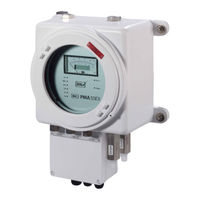
Oxygen – Analyzer
Brand:
M&C
| Category:
Measuring Instruments
| Size: 3 MB
Table of Contents
Dear Customer
2
Table of Contents
3
List of Illustrations
4
General Information
5
Declaration of Conformity
5
Safety Instructions
6
Intended Use
6
Warranty
6
Used Terms and Signal Indications
7
Qualified Personnel
7
Introduction
9
Serial Number
9
Power Supply
9
Application
9
Technical Data
10
Options
11
Description
12
Figure 1 Dimensions PMA30
12
Figure 2 Wall-Mount Housing (Version Since 05.2024)
12
Front Panel
13
Figure 3 Front Panel PMA30
13
Option Process Pressure Compensation Type PD (Without SIL Certification)
14
Option Zero Suppression with Process Pressure Compensation Type SD/PD (Without SIL-Certification)
14
The Measuring Principle
15
Figure 4 Scheme of the Measuring Cell and Optical Signal Processing
15
Gas Flow Diagram of the Analyzer PMA30
16
Receipt of Goods and Storage
16
Installation
17
Connection of Sample Gas Inlet and Sample Gas Outlet
17
Standard Gas Conditioning System
18
Electrical Connection
18
Figure 6 Standard Gas Conditioning System
18
Analog Signal Output
19
Figure 7 Back Side PMA30
19
Description 0/4-20Ma Outlet
20
Adjustment of the Current Signal Outlet
20
Adjustment of the Load
20
Adjustment of the Max. Current Signal at the Ma-Outlet
20
Description 0-10 V Outlet
21
Status Signal
21
Figure 8 Pin Assignment of D-Sub-Connector X4
21
Remote Range Control and External Measuring Range Indication
22
Figure 9 Pin Assignment of D-Sub-Connector X1
22
Preparations for Commissioning
23
Starting up
23
Calibration
23
Zero Calibration
24
Span Calibration
25
Output Signal
26
Measuring
27
Cross Sensitivities
27
Closing down
31
Storage and Transport
31
Maintenance
31
Removal of the Measuring Cell
32
Figure 10 Transmitter Unit
33
Mechanical Zero Point Adjustment
34
Figure 11 Schematic View of the Transmitter Unit
35
Trouble Shooting
36
Proper Disposal of the Device
37
Spare Parts List
37
Risk Assessment
37
Figure 12 Overview Risk Assessment
38
Appendix
40
Operating Conditions
42
Figure 13 Circuit Diagram PMA30 Main Board
43
Figure 14 Assembly Diagram PMA30 Main Board
44
Figure 15 Circuit Diagram PMA30 Front Board
47
Figure 16 Assembly Diagram Front Board PMA30
48
Figure 17 Circuit Diagram Extension Board PMA30
49
Figure 18 Assembly Diagram Extension Board PMA30
50
Figure 19 Connections Wall Mounting Housing PMA30
51
Figure 20 Wall-Mount Housing (Version Since 05.2024) with Cable Glands
52
Advertisement
M&C PMA Series Instruction Manual (53 pages)
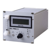
Brand:
M&C
| Category:
Analytical Instruments
| Size: 10 MB
Table of Contents
Table of Contents
3
General Information
5
Declaration of Conformity
5
Electrical Standards
6
Safety Instructions
6
Information and Safety Instructions for Using the Analyzer in Hazardous Areas
7
Proper Use
7
Analyzing Gases from Ex Zone II 1G Ex IIC T4
7
Warranty
8
Used Terms and Signal Indications
8
Introduction
10
Serial Number
10
Application
10
Power Supply
10
Technical Data
11
Options
12
Description
13
Figure 1 PMA50 EX Oxygen Analyzer
13
Pma 50 Ex/P/Pd-1-50 with Pressure Compensation and Enclosure Purging (Without Sil-Certification)
14
PMA 50 Ex/P/Pd with Pressure Compensation (Without SIL-Certification)
15
Option Zero Suppression (Without SIL-Certification)
15
Measuring Principle
15
Option Enclosure Purging or Enclosure Ventilation
15
Figure 2 Drawing of the Measuring Cell and Optical Signal Processing
16
Gas Flow Diagram
17
Figure 3 Gas Flow Diagram
17
Figure 4 Gas Conditioning
18
Receipt of Goods
19
Installation
19
Figure 5 Dimensions for Installation
19
Supply Connections
20
Sample Gas Inlet and Sample Gas Outlet
20
Option Purging Enclosure or Enclosure Ventilation
21
Electrical Connection
22
Figure 6 Electrical Connection Inside the Connection Box of the PMA50 EX
22
Starting up
23
Calibration
23
Zero Calibration
24
Full Scale Value Calibration
25
Measuring
27
Cross Sensitivities
28
Closing down
31
Storage and Transport
31
Maintenance
31
Removal of the Measuring Cell
33
Figure 7 Drawing of the Internal Analyzer Design
33
Figure 8 Transmitter Unit
35
Mechanical Zero Point Adjustment
36
Figure 9 Transmitter Unit for Mechanical Zero Point Adjustment
36
Proper Disposal of the Device
37
Spare Parts List
37
Appendix
38
Figure 10 Circuit Diagram Front Board PMA50 EX
41
Figure 11 Assembly Front Board PMA50 EX
42
Figure 12 Circuit Diagram Mains Adapter PMA50 EX
43
Figure 13 Assembly/Connection Mains Adapter PMA50 EX
44
Figure 14 Cut-Out Magnification Front Board for Adjustment of Temperature Alarm (TP10, P19) (TP11: Current Temperature) und Flow Alarm Threshold (P20)
45
Figure 15 Cut-Out Magnification Front Board Couple Sensor Bridge for Application of a Transmitter
45
Figure 16 Cut-Out Magnification Front Board for Adjustment of Reference Voltage , Amplification and Offset of the O
46
Figure 17 Cut-Out Magnification Mains Adapter for Adjustment of the Temperature, Current and
47
Figure 18 Cut-Out Magnification Mains Adapter for Adjustment of Burden and Limitation of the
47
M&C PMA Series Instruction Manual (50 pages)
Oxygen – Analyzer
Brand:
M&C
| Category:
Measuring Instruments
| Size: 3 MB
Table of Contents
Table of Contents
3
General Information
5
Declaration of Conformity
5
Safety Instructions
6
Warranty
6
Used Terms and Signal Indications
7
Introduction
8
Serial Number
8
Application
8
Power Supply
8
Technical Data
9
Options
10
Description
11
Figure 1 Dimensions PMA30
11
Front Panel
12
Option Process Pressure Compensation Type PD (Without SIL Certification)
13
Option Zero Suppression with Process Pressure Compensation Type Sd/Pd (Without Sil-Certification)
13
The Measuring Principle
13
Gas Flow Diagram of the Analyzer PMA 30
14
Figure 3 Figure
14
Receipt of Goods and Storage
15
Installation
16
Connection of Sample Gas Inlet and Sample Gas Outlet
16
Standard Gas Conditioning System
17
Electrical Connection
17
Figure 5 Standard Gas Conditioning System
17
Analog Signal Output
18
Description 0/4-20Ma Outlet
19
Adjustment of the Current Signal Outlet
19
Adjustment of the Load
19
Adjustment of the Max. Current Signal at the Ma-Outlet
19
Description 0-10 V Outlet
20
Status Signal
20
Remote Range Control and External Measuring Range Indication
21
Figure 7 Figure
21
Starting up
22
Calibration
22
Zero Calibration
22
Span Calibration
24
Measuring
25
Cross Sensitivities
27
Closing down
30
Storage and Transport
30
Maintenance
30
Removal of the Measuring Cell
31
Figure 9 Transmitter Unit
32
Mechanical Zero Point Adjustment
33
Trouble Shooting
35
Proper Disposal of the Device
36
Spare Parts List
36
Appendix
37
Figure 11 Circuit Diagram PMA30 Main Board
40
Figure 12 Assembly Diagram PMA 30 Main Board
41
Figure 13 Circuit Diagram PMA 30 Front Board
43
Figure 18 PMA 30 in Wall Mounting Housing
48
Advertisement
M&C PMA Series Instruction Manual (32 pages)
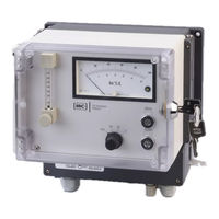
Portable Oxygen Analyzer
Brand:
M&C
| Category:
Measuring Instruments
| Size: 1 MB
Table of Contents
Dear Customer
2
Table of Contents
3
List of Illustrations
4
General Information
5
Declaration of Conformity
5
Safety Instructions
6
Intended Use
6
Warranty
6
Used Terms and Signal Indications
7
Qualified Personnel
7
Introduction
9
Serial Number
9
Application
9
Technical Data
10
Description
11
Front Panel
12
Figure 1 Dimensions
12
Figure 2 Front Panel
12
Gas Flow Diagram of the Analyzer PMA10(S)
13
Options
13
Approval According to 13. and 17. Bimschv and TA-Luft (Not for PMA10S)
13
Output Signal
13
Rechargeable Battery
13
Figure 3 Gas Flow Diagram PMA10(S)
13
Sample Gas Pump
14
Alarm Contact Outlet (Not for PMA10S)
14
The Measuring Principle
14
Figure 4 Scheme of the Measuring Cell and Optical Signal Processing
14
Receipt of Goods and Storage
15
Installation
15
Connection of Sample Gas Inlet and Sample Gas Outlet
16
Standard Gas Conditioning System
17
Electrical Connection
17
Signal Output
17
Figure 5 Standard Gas Conditioning System
17
Option Alarm Contact Output
18
Contact Assignment
18
Adjustment of the Alarm Threshold
18
Figure 6 Plug Connection Signal Output
18
Contact Rating
18
Connections on the Rear Side
19
Preparations for Commissioning
19
Starting up
19
Figure 7 Rear Side
19
Version with Rechargeable Battery
20
Calibration
21
Zero Calibration
21
Cross Sensitivities
22
Consideration of Cross Sensitivities
23
Span Calibration
25
Measuring
26
Closing down
26
Maintenance
27
Check and Change of the Internal Filter Element
27
Figure 8 PMA10(S) with Open Housing
27
Trouble Shooting
28
Proper Disposal of the Device
28
Spare Parts List
28
Risk Assessment
29
Figure 9 Overview Risk Assessment
29
Appendix
31
Figure 10 Assembly of the Components (Drawing-No.: 2355-5.01.0)
32
M&C PMA Series Instruction Manual (28 pages)
Brand:
M&C
| Category:
Analytical Instruments
| Size: 2 MB
Table of Contents
Table of Contents
2
General Information
4
Declaration of Conformity
4
Safety Instructions
5
Warranty
5
Used Terms and Signal Indications
6
Introduction
7
Serial Number
7
Application
7
Technical Data
8
Description
9
Figure 1 Dimensions PMA20
9
Front Panel
10
Gas Flow Diagram of the Analyser PMA 20
10
Figure 2 Front Panel PMA20
10
Figure 3 Gas Flow Diagram PMA 10
10
The Measuring Principle
11
Figure 4 Scheme of the Measuring Cell and Optical Signal Processing
11
Receipt of Goods and Storage
12
Installation
12
Connection of Sample Gas Inlet and Sample Gas Outlet
13
Standard Gas Conditioning System
13
Figure 5 Standard Gas Conditioning System
13
Electrical Connection
14
Signal Output
14
Starting up
14
Figure 6 Electrical Connection PMA 20
14
Calibration
15
Zero Calibration
15
Cross Sensitivities
17
Consideration of Cross Sensitivities
18
Span Calibration
19
Measuring
21
Closing down
21
Maintenance
21
Trouble Shooting
21
Spare Parts List
22
Appendix
22
Figure 7 Circuit Diagram PMA 20
23
Figure 8 Circuit Diagram Oxygen Transducer Unit PMA1.02.0
24
Figure 9 Components List Circuit Diagram PMA1.02.0
25
Figure 10 Components List Circuit Diagram PMA1.02.0
26
Figure 11 Temperature Sensor Resistance Dependent on Temperature
27
Figure 12 Installation Provisions and Spare Parts Positions
28
M&C PMA Series Instruction Manual (24 pages)
Brand:
M&C
| Category:
Measuring Instruments
| Size: 1 MB
Table of Contents
Table of Contents
3
General Information
4
Declaration of Conformity
4
Safety Instructions
5
Warranty
5
Used Terms and Signal Indications
6
Introduction
7
Serial Number
7
Power Supply
7
Application
7
Technical Data
8
Description
9
Figure 1 Dimensions of Oxygen Analyzer PMA 45K1
9
Figure 2 PMA 45K1
10
Measuring Principle
11
Figure 3 Diagram of the Measuring Cell and Optical Signal Processing
11
Gas Flow Chart
12
Figure 4 Gas Flow Chart
12
Receipt of Goods
13
Installation
13
Power Supply Connections
14
Sample Gas Inlet and Outlet
14
Electrical Connection
14
Determination of the Two Measuring Ranges to be Selected on the Instrument
15
Figure 5 Electrical Connections PMA 45K1
15
Starting up
16
Figure 6 Determination of Measuring Range Via Jumpers
16
Calibration
17
Zero Point Adjustment
17
Cross Sensitivities
19
Consideration of Cross Sensitivities
20
Sensitivity Adjustment
21
Measuring
23
Closing down
23
Storage
23
Maintenance
23
Annexe
24
Advertisement
Related Products
M&C PMA 45K1
M&C PMA 30/D
M&C PMA 30/A/D
M&C GenTwo PMA1000V2.4
M&C PMA10
M&C PMA10S
M&C PMA 50 EX
M&C PMA 05
M&C PMA05 MB01
M&C PMA 20
M&C Categories
Measuring Instruments
Water Pump
Accessories
Laboratory Equipment
Industrial Equipment
More M&C Manuals
Login
Sign In
OR
Sign in with Facebook
Sign in with Google
Upload manual
Upload from disk
Upload from URL