M&C PMA Series Instruction Manual
Oxygen – analyzer
Hide thumbs
Also See for PMA Series:
- Instruction manual (54 pages) ,
- Instruction manual (32 pages) ,
- Instruction manual (28 pages)

Related Manuals for M&C PMA Series


Summary of Contents for M&C PMA Series
- Page 1 ® Oxygen – Analyzer Series PMA PMA 30/D, PMA 30/A/D Instruction Manual Version 1.01.03...
- Page 2 Dear customer, Thank you for buying our product. In this manual you will find all necessary information about this M&C product. The information in the manual is fast and easy to find, so you can start using your M&C product right after you have read the manual.
-
Page 3: Table Of Contents
Content General information ............................... 5 Declaration of conformity ............................. 5 Safety instructions ..............................6 Warranty ................................... 6 Used terms and signal indications ........................7 Introduction ................................8 Serial number ..................................... 8 Power supply ....................................8 Application ................................8 Technical data ................................9 Options ...................................... - Page 4 List of Illustrations Figure 1 Dimensions PMA30 ................................11 Figure 2 Front panel PMA 30 ................................12 Figure 3 Scheme of the measuring cell and optical signal processing ................. 14 Figure 4 Gas flow diagram PMA 30 ..............................14 Figure 5 Standard gas conditioning system ..........................
-
Page 5: General Information
HEAD OFFICE M&C TechGroup Germany GmbH Rehhecke 79 40885 Ratingen Germany Telephone: 02102 / 935 – 0 Fax: 02102 / 935 – 111 E - mail: info@mc-techgroup.com www.mc-techgroup.com GENERAL INFORMATION The product described in this operating manual has been examined before delivery and left our works in perfect condition related to safety regulations. -
Page 6: Safety Instructions
SAFETY INSTRUCTIONS Please take care of the following basic safety procedures when mounting, starting up or operating this equipment: Read this operating manual before starting up and use of the equipment. The information and warnings given in this operating manual must be heeded. Any work on electrical equipment is only to be carried out by trained specialists as per the regulations cur- rently in force. -
Page 7: Used Terms And Signal Indications
USED TERMS AND SIGNAL INDICATIONS This means that death, severe physical injuries and/or important material damages will occur in case the respective safety measures are not fulfilled. D A N G E R ! This means that death, severe physical injuries and/or important material damages may occur in case the respective safety measures are not ful- filled. -
Page 8: Introduction
INTRODUCTION The M&C oxygen analyzer PMA 30 is a temperature-controlled instrument which has been designed for continuous measurements of oxygen concentrations in particle free and dry sample gas. SERIAL NUMBER The type plate with the serial number is on the back of the analyzer. Whenever you call M&C regarding questions or orders for the spares please give us the serial number of your PMA 30. -
Page 9: Technical Data
TECHNICAL DATA Version PMA 30/D, PMA 30A/D Oxygen analyzer Series PMA PMA 30/D 230 V 50 Hz, Part No. 03A2005 PMA 30/D 115 V 60 Hz, 03A2005a PMA 30A/D 230 V 50 Hz, 03A2001 PMA 30A/D 115 V 60 Hz 03A2005a Power supply 230 V AC (standard) or 115 V AC available (a)*... -
Page 10: Options
Version PMA 30/D, PMA 30A/D Oxygen analyzer Series PMA Platinum, Glass, PTFE, PVDF, Stainless Steel 316Ti, FKM, Epoxy resin Materials in contact with sample gas Sample gas connection 1/8" NPT i thermo-conductive flow sensor downstream mounted after measuring cell Flow alarm Status alarm 2 x change over contact, potential free, max. -
Page 11: Description
DESCRIPTION The PMA 30 is a reliable and easy-to-operate instrument. It is built into a compact 19-inch cassette. The transducer unit maintains a constant operating temperature of 55 °C and a flashing LED on the control panel indicates the proper operating temperature of the analyzer. The five measuring ranges are displayed on the analogue meter with 30 and 100 % scale. -
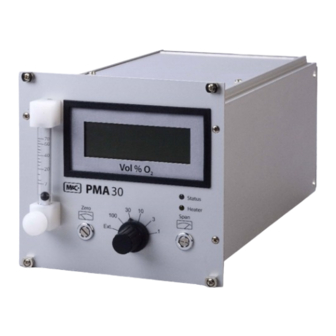
Page 12: Front Panel
FRONT PANEL Analog indication Needle valve 7 - 70 Nl/h Zero potentiometer Measuring range selector switch Span potentiometer LED - heating control Flow meter LED – alarm status Figure 2 Front panel PMA 30 PMA30 | 1.01.03 www.mc-techgroup.com... -
Page 13: Option Process Pressure Compensation Type Pd (Without Sil Certification)
OPTION PROCESS PRESSURE COMPENSATION TYPE PD (WITHOUT SIL CERTIFICATION) In case of barometric or process originated pressure variations, the PMA 30 can be equipped with a special pressure compensation. The compensation can be effected within a pressure range of 0.6 – 1.6 bar abs.. Thereby errors in measurement caused by pressure variations can be eliminated. -
Page 14: Gas Flow Diagram Of The Analyzer Pma 30
Figure 3 Scheme of the measuring cell and optical signal processing The measuring cell consists of two nitrogen-filled spheres which are arranged in the form of a dumbbell. In the dumbbell’s central point of rotation, a small mirror is placed. The dumbbell is surrounded by a wire coil needed for the compensation procedure. -
Page 15: Receipt Of Goods And Storage
The measuring cell 3 must absolutely be protected against dust particles. Therefore, the preceding external gas conditioning system should be equipped with a fine filter 1 of at least 2 micron filter porosity (eg. type FP-2T). The maximum gas flow of 60 Nl/h is adjusted via flow meter 2 with needle valve on the front plate. A flow sensor 4 in the outlet of the measuring cell is controlling the gas flow through the cell according to the measuring principle of thermal conductivity. -
Page 16: Installation
INSTALLATION The PMA 30 is intended for stationary operation. In combination with a gas conditioning according to the requirements a long-lasting operability and a minimum of maintenance is guaranteed. The sample gas must be dust free and dry to prevent a contamination and condensation in the analyzer. -
Page 17: Standard Gas Conditioning System
13.2 STANDARD GAS CONDITIONING SYSTEM PMA 30 +5°C Figure 5 Standard gas conditioning system 1 : Heated gas sample probe (e.g. probe SP2000-H) 2 : Heated gas sample line (e.g. 4M4/6) 3 : Sample gas cooler (e.g. ECM-1G) 4 : Peristaltic pump or condensate collecting vessel (e.g. -
Page 18: Analog Signal Output
1 = Gas IN 1/8“ NPTi 5/6 = Mains fuses (L and N) 2 = Option purge gas connection 4/6 7 = Mains IN / connector plug 3 = Gas OUT 1/8“ NPTi 8 = D-Sub-connector 25-pole for remote control 4 = D-Sub-connector 9-pole for signal outlet and indication Figure 6... -
Page 19: Description 0/4-20Ma Outlet
13.3.2 DESCRIPTION 0/4-20MA OUTLET Every measuring range meets 0/4-20 mA (standard measuring ranges: 0-1 %; 0-3 %; 0-10 %; 0-30 %; 0-100 % O Current range switchable (see 13.3.3; 4-20 mA standard factory setting) Galvanically isolated (internal power supply) ... -
Page 20: Description 0-10 V Outlet
13.3.6 DESCRIPTION 0-10 V OUTLET 0-10 V always correspond to 100 % O independent of the measuring range For a load of > 100 KOhm Linear from -0.5 V to 11 V General evaluation of the 0-10 V signal: Measuring Range Measuring Range Measuring Range... -
Page 21: Remote Range Control And External Measuring Range Indication
13.3.8 REMOTE RANGE CONTROL AND EXTERNAL MEASURING RANGE INDICATION The 25-pole D-sub-connector X1 (see figure 8) allows the connection for the remote range control. For release of this remote range control the measuring range selection switch at the front panel of the PMA30 (see figure 2, no. -
Page 22: Starting Up
STARTING UP Check electrical connections and gas connections. Check mechanical zero of the indication; if necessary adjust zero position by turning the slotted screw in the pane of the indication instrument. Turn measuring range selection switch to 30 %. ... - Page 23 Purge the pressure reducer and the complete hose line for approximately 5 sec.; Check the adjusted control pressure and reduce if necessary to ≤ 0.1 bar, then shut off the pressure reducer valve again. Connect the free hose end of the zero gas bottle connection to the gas inlet of the analyzer or if existing to the external calibration valve;...
-
Page 24: Span Calibration
15.2 SPAN CALIBRATION In case the oxygen concentration of the sample gas is below 30 % O the calibration can be performed with dry air. Should the concentra- tions be higher, ideally, the test gas should correspond to the span N O T E ! value! Before calibrating the span value, always check the zero point. -
Page 25: Measuring
The signal to be measured can be calculated as follows: (max. signal output - min. signal output) x Concentration [%] Measured value + min. Signal output Measuring range span value [%] A test gas concentration of 20.93% (air) would result in the following: Output signal Signal to be measured with span value 100 %... - Page 26 Basically measurements should be carried out only with flow quantity and room temperature held constant. N O T E ! PMA30 | 1.01.03 www.mc-techgroup.com...
-
Page 27: Cross Sensitivities
CROSS SENSITIVITIES The following table shows the cross sensitivities of the most important gases at 20 °C and 50 °C. All values are based on a zero calibration with N and a span calibration with 100 vol% O . The deviations are each valid for 100 vol% of the respective gas. - Page 28 The selectivity of the above mentioned measuring principle is based on the high susceptibility of oxygen to other gases (see table). The following examples shall show how cross sensitivities can be considered for the zero calibration. Example 1: Determination of the rest content of oxygen in a 100% carbon dioxide (CO protective atmosphere at 20 °C In the table of cross sensitivities, you can read the value for CO at 20 °C of –0.27.
- Page 29 The correction factor is calculated as follows: Correction factor (100 – O -concentration) It is incidental: = 1.0526 (100 – 5) For the gas mixture the rectified sum cross sensitivity then is calculated in good approximation: 1.0526 x -0.1123 vol% = -0.1182 vol% The rectified sum cross sensitivity with change of sign now can be used for the correction of the zero calibra- tion.
-
Page 30: Closing Down
For the gas mixture in example 2 the rectified sum cross sensitivity then is calculated in good approximation for 20.93 vol% oxygen: 0.7907 x -0.1182 vol% = -0.0935 vol% The rectified sum cross sensitivity with change of sign now can be used for the correction of the span cali- bration. -
Page 31: Removal Of The Measuring Cell
The preceding components necessary for the sample gas conditioning are to be maintained according to the respective operating manuals. The zero point and full scale calibration must be performed with the appropriate test gases according to the instructions. Recommended interval of calibration for standard applications: 1 x per week. 20.1 REMOVAL OF THE MEASURING CELL For dismounting the measuring cell, the following procedure is recommended:... -
Page 32: Figure 9 Transmitter Unit
Electrical connections meas. cell Heater element Gas outlet measuring cell Transmitter board Gas inlet measuring cell Temperature cut out at 72 °C Fastening screw for measuring cell Temperature sensor Figure 9 Transmitter unit ... -
Page 33: Mechanical Zero Point Adjustment
In case there are minimally different positions of the dumpbells inside the measuring cells when mounting a new cell, it is absolutely necessary to adjust the zero point mechanically. The PMA30 housing can remain open for this purpose; Fix earthing cable (geen-yellow) of the transmitter unit; ... - Page 34 1 IR LED 5 Heater element 2 Temperature cut out (72 °C) 6 Adjustment screw photocell 3 Sample gas heating coil 7 Measuring cell 4 Fastening screw photocell 8 Photocell Figure 10 Schematic view of the transmitter unit Open the housing of the analyzer; ...
-
Page 35: Trouble Shooting
TROUBLE SHOOTING Error Possible reason Check/Repair No indication No supply voltage Check supply voltage according to type plate. Check whether mains cable is plugged in accurate. Check fine fuse in the low heat device socket. Check fine fuses F1, F2 (TR5) on main board (next to trans- former) No sample gas flow Sample line or filter is blocked... -
Page 36: Proper Disposal Of The Device
PROPER DISPOSAL OF THE DEVICE At the end of the life cycle of our products, it is important to take care of the appropriate disposal of obsolete electrical and non-electrical devices. To help protect our environment, please follow the rules and regulations of your country regarding recycling and waste management. -
Page 37: Appendix
APPENDIX Safety manual according to SIL Circuit diagram main board PMA 30 Assembly diagram main board PMA 30 Jumper-Settings, test points, plugs for main-, front- and extension board Circuit diagram front board PMA 30 Assembly diagram front board PMA 30 ... - Page 38 Extra charge for electrical zero suppressing with process pressure compensation type SD/PD for PMA30, pressure 03A9535 range 0.6bar, media wetted parts : stainless steel, PVDF, FKM. Not with SIL-certification! 03A9530 Extra charge for process pressure compensation type PD for PMA30, pressure range 0.6 bar, media wetted parts : stainless steel, PVDF, FKM.
- Page 39 The sample gas has to be dry (dew point 5 °C) and dust free and the sample gas inlet temperature is not allowed to exceed 50 °C. Generally a fine filter with min. 2 μm has to be installed upstream. Sample gas has to discharge freely into atmosphere at the sample gas outlet because a pressure rise at the outlet and therefore in the measuring cell will result in false readings.
-
Page 40: Figure 11 Circuit Diagram Pma30 Main Board
Figure 11 Circuit diagram PMA30 main board PMA30 | 1.01.03 www.mc-techgroup.com... -
Page 41: Figure 12 Assembly Diagram Pma 30 Main Board
LED alarm short-circuit Flow alarm max. Couple signal Measuring range selection switch Measuring range lower deviation Measuring range exceedance Low temperature alarm +15 V power alarm -15 V power alarm Excess temperature alarm Flow alarm min. LED alarm open Offset O2 2. Op.-level Temperature alarm Range overflow alarm set point 5V reference O2-signal 0-10 V range... - Page 42 PMA30 Main board Connections Test points Power In TP1 O in 2. op. level 0-5 V Temperature fuse TP2 Temperaturalarm Sollwert Temperature sensor TP3 GND Heating TP4 Temperature actual value Current-, voltage-, status signal TP5 O in 1. op. level Measuring range choice, indication, TP6 GND compensation...
-
Page 43: Figure 13 Circuit Diagram Pma 30 Front Board
PMA30 Front board Connection Test points SV1: to extension board None SV2: to main board to digital display Jumper Setting JP1: Signal to dig. display 2+3: compensated 1+2: non compensated Figure 13 Circuit diagram PMA 30 front board www.mc-techgroup.com PMA30 | 1.01.03... - Page 44 Figure 14 Assembly diagram front board PMA 30 PMA30 | 1.01.03 www.mc-techgroup.com...
- Page 45 Figure 15 Circuit diagram extension board PMA 30 www.mc-techgroup.com PMA30 | 1.01.03...
- Page 46 Span zero suppression Offset zero suppression Offset 0-5 V suppressed compensation Span 0-5 V suppressed compensation Span 0-5 V compensated Zero 0-5 V compensated Zero 0-10 V compensated Span 0-10 V compensated 5 V ref. Zero pressure measurement Span pressure measurement Figure 16 Assembly diagram extension board PMA 30 PMA30 | 1.01.03...
- Page 47 Figure 17 Connections wall mounting housing PMA 30 www.mc-techgroup.com PMA30 | 1.01.03...
-
Page 48: Figure 18 Pma 30 In Wall Mounting Housing
Figure 18 PMA 30 in wall mounting housing PMA30 | 1.01.03 www.mc-techgroup.com... - Page 49 www.mc-techgroup.com PMA30 | 1.01.03...
- Page 50 PMA30 | 1.01.03 www.mc-techgroup.com...
Need help?
Do you have a question about the PMA Series and is the answer not in the manual?
Questions and answers