M&C PMA Series Instruction Manual
Hide thumbs
Also See for PMA Series:
- Instruction manual (54 pages) ,
- Instruction manual (50 pages) ,
- Instruction manual (32 pages)

Related Manuals for M&C PMA Series


Summary of Contents for M&C PMA Series
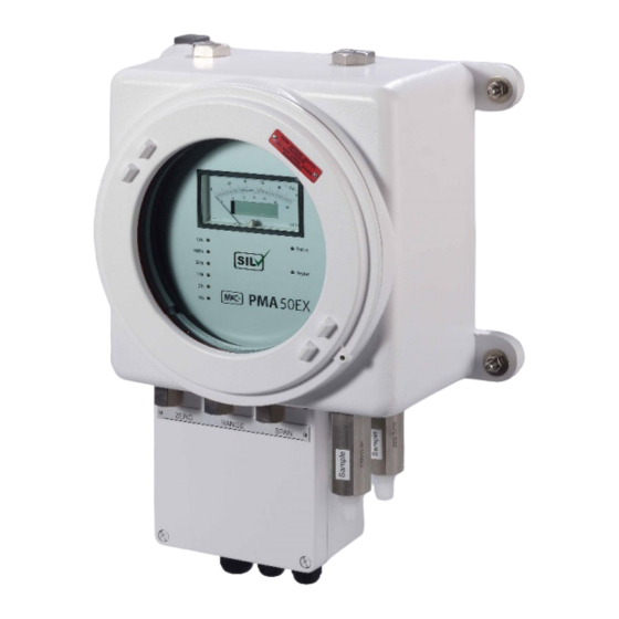
- Page 1 ® Oxygen Analyzer Series PMA PMA 50 EX (Effective from: March 2018, Serial No. 1803436) Instruction Manual Version 1.01.04...
- Page 2 Dear customer, Thank you for buying our product. In this instruction manual you will find all necessary information about this M&C product. The information in the instruction manual is fast and easy to find, so you can start using your M&C product right after you have read the manual.
-
Page 3: Table Of Contents
List of Contents General information ..........................5 Declaration of conformity ........................5 Electrical standards ..........................6 Safety instructions ..........................6 Proper Use ....................................7 Information and safety instructions for using the Analyzer in hazardous areas ......7 Analyzing gases from Ex zone II 1G Ex IIC T4 ..................... - Page 4 List of Illustrations Figure 1 PMA50 EX oxygen analyzer ............................13 Figure 2 Drawing of the measuring cell and optical signal processing ..............16 Figure 3 Gas flow diagram ................................17 Figure 4 Gas conditioning ................................18 Figure 5 Dimensions for installation ............................19 Figure 6 Electrical connection inside the connection box of the PMA50 EX ............
-
Page 5: General Information
Head Office M&C TechGroup Germany GmbH Rehhecke 79 40885 Ratingen Germany Telephone: 02102 / 935 - 0 Fax: 02102 / 935 - 111 E - mail: info@mc-techgroup.com www.mc-techgroup.com GENERAL INFORMATION The product described in this instruction manual has been examined before delivery and left our works in perfect condition related to safety regulations. -
Page 6: Electrical Standards
ELECTRICAL STANDARDS The electrical standard of electrical equipment corresponds to the safety regulations concerning the EN61010 and to the safety requirements of the European standards: EN 61010 EN 61508 EN 60079-0:2012+A11:2013 EN 60079-1:2014 EN 60079-7:2015 for operation of the equipment in hazardous areas group II category 2. -
Page 7: Information And Safety Instructions For Using The Analyzer In Hazardous Areas
PROPER USE The oxygen analyzer PMA50 EX is suitable for analyzing gas mixtures classified in Zone 1 with an oxygen content of up to 21% by volume. The PMA50 EX is suitable for the continuous measurement of oxygen in particle-free and dry sample gases with a maximum dew point of 5 °C [41 °F]. Only install and operate the analyzer under the operating parameters and conditions described in chapter 5 “Information and safety instructions for using the Analyzer in hazardous areas”... -
Page 8: Warranty
WARRANTY If the equipment fails, please contact M&C directly or else go through your M&C authorised dealer. We offer a one year warranty as of the day of delivery as per our normal terms and conditions of sale, and assuming technically correct operation of the unit. Consumables are hereby excluded. The terms of the war- ranty cover repair at the factory at no cost or the replacement at no cost of the equipment free ex user location. - Page 9 High voltages! Protect yourself and others against damages which might be caused by high voltages. Corrosive! These substances destroy living tissue and equipment upon contact. Do not breathe vapors; avoid contact with skin and eyes. Hot surface! Contact may cause burn! Do not touch! Wear protective gloves! Working with chemicals, sharp objects or extremely high temperatures re- quires wearing protective gloves.
-
Page 10: Introduction
INTRODUCTION SERIAL NUMBER The type plate with the serial number is fixed on the left side of the analyzer’s housing. Please indicate always this serial number in case of questions or when purchasing spare parts. POWER SUPPLY The internal power supply of the oxygen analyzer PMA50 EX is 115 V or 230 V AC, 40 - 60 Hz. Detailed infor- mation can be found on the type plates. -
Page 11: Technical Data
TECHNICAL DATA 05A1000 PMA 50 EX, power supply 230 V, pressure range 0.6 to 1.1 bar abs. 05A1000a PMA 50 EX, power supply 115 V, pressure range 0.6 to 1.1 bar abs. 05A2500 PMA 50 EX/P/PD-1-50, power 230 V, (not with SIL-certification) pressure compensation 0.6 to 1.5 bar abs. -
Page 12: Options
-10 up to +50 °C [14 up to 122 °F] dry gas Temperature of sample gas Fixed at +55 °C [131 °F] (factory-set) -Transmitter temperature At 72 °C [161.6 °F] via thermal fuse, non-reversible Temperature cut-off 0 to +50 °C [32 to 122 °F] Ambient temperature -20 to +60 °C [-4 to 140 °F] at relative air moisture of 0-90 % r.h. -
Page 13: Description
DESCRIPTION The main part of the PMA50 EX is the paramagnetic oxygen measuring cell. This measuring principle is one of the most precise quantitative methods for determination of the oxygen contents in the range of 0-100 vol% O The Oxygen Analyzer PMA50 EX is destined for stationary operation. The mounting into an Ex db eb IIC T4 housing with breathing and draining devices in the sample gas inlet and outlet , allows the analyzer to be... -
Page 14: Pma 50 Ex/P/Pd-1-50 With Pressure Compensation And Enclosure Purging (Without Sil-Certification)
A window in the housing of the analyzer enables the control of the analog/digital measured value display 15, the heating control LED and status LED 14, as well as the measuring range LEDs and 6. All operating elements are accessible from the outside and guarantee simple and user-friendly handling dur- ing calibration as well as measuring range switching. -
Page 15: Pma 50 Ex/P/Pd With Pressure Compensation (Without Sil-Certification)
The enclosure purging has to flow off atmospherically free! 11.2 PMA 50 EX/P/PD WITH PRESSURE COMPENSATION (WITHOUT SIL-CERTIFICATION) In case of barometric or process-related pressure variations, the PMA50 EX can be equipped with a special pressure compensation. The pressure can be compensated in a range of 0.6 to 1.1 bar abs. This can eliminate measurement errors due to pressure fluctuations. -
Page 16: Figure 2 Drawing Of The Measuring Cell And Optical Signal Processing
GAS INLET GAS OUTLET 1 Nitrogen-filled spheres 6 Photo cell 2 Tightening strap out of platinum 7 Measuring amplifier 3 Small mirror 8 Measuring amplifier 4 Wedge-shaped pole pieces 9 Display 5 Projektions-LED Figure 2 Drawing of the measuring cell and optical signal processing The measuring cell consists of two hollow spheres 1 filled with nitrogen, which are formed into a dumbbell. -
Page 17: Gas Flow Diagram
GAS FLOW DIAGRAM Figure 3 shows the gas flow diagram of the Oxygen Analyzer PMA50 EX. 1 : External fine filter 4 : Measuring cell 5 : Flow alarm sensor 2 : External flow meter 3 : breathing and draining device 6 : breathing and draining device Figure 3 Gas flow diagram... -
Page 18: Figure 4 Gas Conditioning
Figure 4 shows the structure of the conditioning system according to the above-mentioned specification. I Atmospheric pressure Sample gas Condensate Max 1.1 bar abs. Sample gas outlet II Overpressure Max 1.1 bar abs. Sample gas outlet 1 Gas cooler 7 Pressure display 2 Fine filter 8 Overflow valve 3 Flow meter 6-60 Nl/h... -
Page 19: Receipt Of Goods
RECEIPT OF GOODS The analyzer PMA50 EX is a completely pre-installed unit. Please take the analyzer and possible special accessories carefully out of the packaging material immedi- ately after arrival, and compare the goods with the items listed on the packing list; ... -
Page 20: Supply Connections
When using the analyzer outdoors, it must be protected against the effects of the weather. If possible, the installation should be done in constant climatic ambient conditions. A vibration-free location is ideal for installation. If this is not possible, antivibration mounts must be used to decouple the housing. -
Page 21: Option Purging Enclosure Or Enclosure Ventilation
16.2 OPTION PURGING ENCLOSURE OR ENCLOSURE VENTILATION According to the Ex-Certificate (see annexe) purging of the enclosure is also required in case of increased inlet pressure of 1.1 to max. 1.5 bar abs. To do this, choose the option Part No. 05A9005. For increased pressure and corrosive gases, the analyzer must be equipped with the option enclosure purging (Part No. -
Page 22: Electrical Connection
16.3 ELECTRICAL CONNECTION If you do not use the correct supply voltage, the equipment may be destroyed. Please take care of the correct supply voltage as indicated on the type plate. Warning The equipotential bonding terminals of the analyzer housing and the terminal box must always be connected in case of installation in hazardous area. -
Page 23: Starting Up
STARTING UP The following steps must be carried out when commissioning the analyzer: Before starting the equipment for the first time, check that the electrical connections and the gas connec- tions have been executed as requested. The voltage indicated on the type plate must correspond to the mains supply. -
Page 24: Zero Calibration
18.1 ZERO CALIBRATION To do a zero-point calibration of the analyzer, use an O2-free gas, e.g. nitrogen (N ) 5.0. Follow the steps below: Connect the flexible PVC or Viton tube with the bottle’s pressure reducer of the N -zero gas bottle;... -
Page 25: Full Scale Value Calibration
After zero calibration, the full scale value must also be calibrated! Note 18.2 FULL SCALE VALUE CALIBRATION For oxygen concentrations of the sample gas below 30 % O , dry air can be used for calibration. Higher concentrations ideally require a test gas corresponding to the full scale value! Note Before calibrating the full scale value, always check the zero point. - Page 26 Check the analog output signals; The signal to be measured can be calculated as follows: (max. signal output - min. signal output) x Concentration [%] Measured value = + min. Signal output Full scale value [%] A test gas concentration of 20.93 % (air) would result in the following: Output signal Signal to be measured with full scale value 100 %...
-
Page 27: Measuring
MEASURING During initial commissioning at a new measurement location, all the steps described above must be followed. The accuracy requirements for the analysis determine the interval of recalibration. The sample gas quantity should be adjusted between 10 Nl/h and 60 Nl/h air (external flow meter). After selecting the desired measuring range, the analyzer is ready for measurement. -
Page 28: Cross Sensitivities
CROSS SENSITIVITIES The following table shows the cross sensitivities of the most important gases at 20 °C [68 °F] and 50 °C [122 °F]. All values are based on a zero calibration with N and a full scale value calibration with 100 vol% O . - Page 29 The selectivity of the above mentioned measuring principle is based on the high susceptibility of oxygen to other gases (see table). The following examples shall show how cross sensitivities can be considered for the zero calibration. Example 1: Determination of the rest content of oxygen in a 100 % carbon dioxide (CO ) protective atmosphere at 20 °C [68 °F] In the table of cross sensitivities you can read the value for CO...
- Page 30 The correction factor is calculated as follows: Correction factor = (100 – O -concentration) This results in the following correction factor: = 1.0526 (100 – 5) For the gas mixture, the corrected total cross sensitivity for 0 vol% oxygen is therefore calculated in good approximation: 1.0526 x -0.1123 vol% = -0.1182 vol% The corrected total cross sensitivity with plus/minus sign change can now be used for correction during zero...
-
Page 31: Closing Down
For the gas mixture in example 2 the corrected total cross sensitivity then is calculated in good approximation for 20.93 vol% oxygen: 0.7907 x -0.1182 vol% = -0.0935 vol% The corrected total cross sensitivity with plus/minus sign change now can be used for the correction of the full scale value calibration. - Page 32 The physical measuring principle and the special design of the analyzer minimize the maintenance require- ments. The preceding components necessary for the sample gas conditioning are to be maintained according to the respective instruction manuals. The calibration of zero point and full scale value must be carried out with the corresponding test gases ac- cording to the instructions.
-
Page 33: Removal Of The Measuring Cell
23.1 REMOVAL OF THE MEASURING CELL Figure 7 shows a drawing of the internal analyzer design PMA 50 EX. Electrical connections Sample gas outlet Transmitter type 1.07.X. Flexible tube Hex screws Sample gas inlet Flow sensor, stainless steel Front controller board Union nuts sample gas inlet and outlet Power supply and temperature board Figure 7... - Page 34 For dismounting the measuring cell, the following procedure is recommended: During all work on the analyzer it must be ensured that both the working environ- Warning ment and the analyzer itself are free of explosive or flammable gases! Dangerous voltage. Before performing any maintenance work, disconnect the an- alyzer and all external circuits connected to the analyzer from the power supply.
-
Page 35: Figure 8 Transmitter Unit
Electrical connections meas. cell Heater element Gas outlet measuring cell Transmitter board Gas inlet measuring cell Temperature fuse (cut-off at 72 °C [161.6 °F]) Fastening screw for measuring cell Temperature sensor Figure 8 Transmitter unit ... -
Page 36: Mechanical Zero Point Adjustment
23.2 MECHANICAL ZERO POINT ADJUSTMENT The mechanical zero point adjustment has to be done as described in the following. 5 Heater element Temperature fuse (cut-off at 72 °C [161.6 °F]) 6 Adjustment screw photo cell Sample gas heating coil 7 Measuring cell Fastening screw photo cell 8 Photo cell Figure 9... -
Page 37: Proper Disposal Of The Device
PROPER DISPOSAL OF THE DEVICE At the end of the service life of our products, it is important to take care of the appropriate disposal of obso- lete electrical and non-electrical devices. To help protect our environment, follow the rules and regulations of your country regarding recycling and waste management. -
Page 38: Appendix
APPENDIX Safety handbook according to SIL Circuit diagram front board PMA50 EX Assembly front board PMA50 EX Circuit diagram mains adapter PMA50 EX Assembly / connection mains adapter PMA50 EX Cut-out magnification front board for adjustment of temperature alarm (TP10, P19) (TP11: actual tempera- ture) und flow alarm threshold (P20) ... - Page 39 Safety handbook according to SIL Contemplated devices It was contemplated the PMA 50 EX with part no. 05A1000(a) and the following options: Enclosure ventilation and enclosure purging (part no. 05A9005 and 05A9000), Measuring cell solvant resistant or with glass solder (part no. 90A0009 u. 90A0006) Excluded are the PMA 50 EX/P/PD…...
- Page 40 Operating conditions Ambient conditions: Temperature: 0 °C to +50 °C Pressure: 0.9- 1.1 bar abs. Vibrations have to be avoided. The sample gas has to be dry (dew point 5 °C) and dust free and the sample gas inlet temperature is not allowed to exceed 50 °C.
-
Page 41: Figure 10 Circuit Diagram Front Board Pma50 Ex
Figure 10 Circuit diagram front board PMA50 EX www.mc-techgroup.com PMA 50 EX | 1.01.04... -
Page 42: Figure 11 Assembly Front Board Pma50 Ex
Figure 11 Assembly front board PMA50 EX PMA 50 EX | 1.01.04 www.mc-techgroup.com... -
Page 43: Figure 12 Circuit Diagram Mains Adapter Pma50 Ex
Figure 12 Circuit diagram mains adapter PMA50 EX www.mc-techgroup.com PMA 50 EX | 1.01.04... -
Page 44: Figure 13 Assembly/Connection Mains Adapter Pma50 Ex
Figure 13 Assembly/connection mains adapter PMA50 EX PMA 50 EX | 1.01.04 www.mc-techgroup.com... -
Page 45: Figure 14 Cut-Out Magnification Front Board For Adjustment Of Temperature Alarm (Tp10, P19) (Tp11: Current Temperature) Und Flow Alarm Threshold (P20)
Figure 14 Cut-out magnification front board for adjustment of temperature alarm (TP10, P19) (TP11: current temperature) und flow alarm threshold (P20) Figure 15 Cut-out magnification front board couple sensor bridge for application of a transmitter without couple sensor Failure indication: B15: Flow-min failure B14: Transmitter LED-current failure B11: Transmitter temperature max failure... -
Page 46: Figure 16 Cut-Out Magnification Front Board For Adjustment Of Reference Voltage , Amplification And Offset Of The O
Figure 16 Cut-out magnification front board for adjustment of reference voltage , amplification and offset of the -signal PMA 50 EX | 1.01.04 www.mc-techgroup.com... -
Page 47: Figure 17 Cut-Out Magnification Mains Adapter For Adjustment Of The Temperature, Current And
Figure 17 Cut-out magnification mains adapter for adjustment of the temperature, current and voltage output Figure 18 Cut-out magnification mains adapter for adjustment of burden and limitation of the current output www.mc-techgroup.com PMA 50 EX | 1.01.04... - Page 48 PMA 50 EX | 1.01.04 www.mc-techgroup.com...
- Page 49 www.mc-techgroup.com PMA 50 EX | 1.01.04...
- Page 50 PMA 50 EX | 1.01.04 www.mc-techgroup.com...
- Page 51 www.mc-techgroup.com PMA 50 EX | 1.01.04...
- Page 52 PMA 50 EX | 1.01.04 www.mc-techgroup.com...
- Page 53 www.mc-techgroup.com PMA 50 EX | 1.01.04...
Need help?
Do you have a question about the PMA Series and is the answer not in the manual?
Questions and answers