Sign In
Upload
Manuals
Brands
Leuze electronic Manuals
Barcode Reader
BCL 8 S M 100
Leuze electronic BCL 8 S M 100 Reader Manuals
Manuals and User Guides for Leuze electronic BCL 8 S M 100 Reader. We have
3
Leuze electronic BCL 8 S M 100 Reader manuals available for free PDF download: Technical Description, Original Operating Instructions, Manual
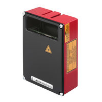
Leuze electronic BCL 8 S M 100 Technical Description (85 pages)
Barcode reader with integrated decoder
Brand:
Leuze electronic
| Category:
Barcode Reader
| Size: 1.55 MB
Table of Contents
Table of Contents
3
1 General Information
8
Explanation of Symbols
8
Declaration of Conformity
8
2 Safety Notices
9
Safety Standards
9
Intended Use
9
Working Safely
10
Figure 2.1: Attachment of the Sticky Labels with Warning Notices at the BCL 34
11
3 Description
12
The Barcode Readers BCL 34
12
Figure 3.1: BCL 34 Device Construction
12
Modular Hoods with Integrated Connectors MS 34 103/MS 34 105
13
Modular Service Display MSD 1 101
13
4 Specifications
14
General Specifications BCL 34
14
LED Indicators
15
General Specifications
15
Table 4.1
15
Device Construction and Components
16
Dimensioned and Connection Drawings
16
Figure 4.1: BCL 34 with MS 34 105
16
Figure 4.2: Dimensioned Drawing BCL 34
16
Figure 4.3: Dimensioned Drawing MS 34 103 / MS 34 105
17
Optical Data
18
Type Overview
18
Table 4.3
18
Type Overview BCL 34 Without Integrated Heating
18
Type Overview BCL 34 with Integrated Heating
18
Raster Aperture
19
Optics Variants and Reading Fields
19
Figure 4.4:BCL 34
19
Figure 4.5:BCL 34
20
Figure 4.6:BCL 34
20
Figure 4.7:BCL 34
21
Figure 4.8:BCL 34
22
Figure 4.9:BCL 34
22
Figure 4.10:BCL 34
23
Automatic Reflector Activation "Autoreflact
24
Figure 4.11:BCL 34
24
Examples of Reflectors Which May be Used
25
Figure 4.12: Reflector Arrangement for Autoreflact
25
5 Accessories / Order Designation
26
Accessories
26
Modular Service Display MSD 1 101
26
Figure 5.1: Modular Service Display MSD 1 101
27
Fastening Accessories
28
Connection Cable KB 034 2000
28
Figure 5.2: Mounting Device BT 56
28
6 Installation
29
Storage, Transportation
29
Figure 6.1: Device Name Plate BCL 34
29
Mounting
30
Figure 6.2: Mounting Example BCL 34
30
Device Arrangement
31
Figure 6.3: Beam Outlet on the BCL 34
31
Figure 6.4: Application Example "Conveyor Chain
32
Address Setting
33
Connection
33
Figure 6.5: View of the Inside of the MS 34
33
Connecting the BCL 34
34
Figure 6.6: Connection Assignment of the BCL 34 with MS 34 103 / MS 34 105
34
Pin Assignment PWR in
35
Pin Assignment SW IN/OUT
35
Table 6.1
35
Pin Assignment DP IN/OUT
36
Table 6.3
36
Mounting the Profibus Connector
37
Figure 6.7: Mounting Profibus Connector
37
Connection of Switching Inputs and Outputs
38
Disassembling, Packing, Disposing
38
Figure 6.8: Connection Diagram Switching Inputs and Outputs BCL 34
38
7 Profibus
39
General Information
39
GSD File
40
Permanently Defined Parameters (Device Parameters)
40
Structure of the Project Modules
42
Overview of the Project Modules
42
Table 7.3
42
Description of the Individual Project Modules
44
Code Table Extension: Modules 1-4
44
Parameters for Modules 1-4
44
Table 7.4
44
Multilabel: Module 5
45
Input Data for Module 5
45
Table 7.5
45
Reading Gate Control: Module 6
46
Output Data Module 5
46
Parameters for Module 6
46
Table 7.7
46
Check Digit: Module 7
47
EAN Designator: Module 8
48
Parameters for Module 7
48
Parameters for Module 8
48
Table 7.9
48
Laser Control: Module 9
49
Figure 7.1: Specifying Switch-On and Switch-Off Positions of the Laser
49
Parameters for Module 10
49
Table 7.11
49
Pharmacode Properties: Module 10
50
Parameters for Module 10
50
Table 7.12
50
Code Type Properties: Module 11
51
Parameters for Module 11
51
Table 7.13
51
Data Formatting: Module 12
52
Parameters for Module 12
52
Switching Input: Module 13
53
Switching Output: Module 14
54
Autoreflact (Automatic Reflector Activation): Module 15
55
Autocontrol: Module 16
56
Reference Code Comparison: Module 17
58
BCL 34 Leuze Electronic
62
Activations: Module 18
64
Activations with ACK: Module 19
65
Decoding State: Module 20
66
Decoding Result: Modules 21 to 27
66
Fragmented Reading Result: Module 34
68
Table 7.30
68
Parameters for Module 13
68
Input Data for Module 13
68
Output Data for Module 14
68
Reading Gate Activations: Module 35
69
Reading Gate Number: Module 36
69
Table 7.34
69
Input Data for Module 15
69
Input Data for Module 16
69
Number of Scans Per Reading Gate: Module 37
70
Input Data for Module 17
70
Code Position: Module 38
71
Input Data for Module 20
71
Figure 7.2: Relative Position of the Barcode in the Scanner Beam
71
Reading Security (Equal Scans): Module 39
72
Scans Per Barcode: Module 40
72
Input Data for Module 34
72
Input Data for Module 35
72
Scans with Information: Module 41
73
Decoding Quality: Module 42
73
Input Data for Module 36
73
Input Data for Module 37
73
Code Direction: Module 43
74
Number of Digits: Module 44
74
Input Data for Module 38
74
Input Data for Module 39
74
Code Type: Module 45
75
Input Data for Module 40
75
Alignment Mode: Module 46
76
Input Data for Module 41
76
Service: Module 47
77
Input Data for Module 42
77
8 Example Configurations
78
Indirect Activation Via the PLC
78
Task
78
Procedure
78
Direct Activation Via the Switching Input
80
Task
80
Procedure
80
Device Parameters for Example Configuration 2
80
Direct Activation Via the Switching Input
82
Task
82
Procedure
82
Device Parameters for Example Configuration 3
82
9 Commissioning
84
Measures to be Performed Prior to the Initial Commissioning
84
Function Test
84
Service Operating Mode
85
10 Maintenance
85
General Maintenance Information
85
Repairs, Servicing
85
Advertisement
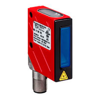
Leuze electronic BCL 8 S M 100 Original Operating Instructions (73 pages)
Bar Code Reader with Integrated Decoder, Smart Sensor Business
Brand:
Leuze electronic
| Category:
Barcode Reader
| Size: 3.52 MB
Table of Contents
Table of Contents
3
1 General Information
6
Explanation of Symbols
6
Declaration of Conformity
6
2 Safety
7
Intended Use
7
Foreseeable Misuse
8
Competent Persons
8
Disclaimer
9
Laser Safety Notices
9
Figure 2.1: Laser Apertures, Laser Warning Signs
11
Figure 2.2: Laser Warning and Laser Information Signs - Supplied Stick-On Labels
12
3 Description
13
The BCL 8 Bar Code Reader
13
Figure 3.1: Device Construction of the BCL 8
13
Stand Alone Operation
14
Daisy Chain Network
14
4 Specifications
15
General Specifications BCL 8
15
Table 4.1
15
Technical Data
15
LED Indicators
16
Table 4.1
16
Dimensioned and Connection Drawings
17
Figure 4.1: Dimensioned Drawing BCL 8 S M
17
Figure 4.2: Dimensioned Drawing BCL 8 S M
18
Optical Data
19
Type Overview
19
Type Overview - M-Optics
19
Table 4.3
19
Type Overview - N-Optics
19
Reading Fields
20
Figure 4.3: Reading Field of BCL 8 S M
20
Figure 4.4: Reading Field of BCL 8 S N
21
5 Accessories / Order Designation
22
Accessories Overview
22
Accessories / Order Codes
22
Table 5.1
22
Connector Unit MA 8.1
23
Figure 5.1: Photo and Dimensioned Drawing of the MA 8.1 Connector Unit
23
Electrical Connection MA 8.1
24
Figure 5.2: Electrical Connection MA 8.1
24
MA 8.1 - PWR in HOST/RS 232 - Voltage Supply and RS 232
25
MA 8.1 - SW IN/OUT - Switching Input and Switching Output
25
Figure 5.1: MA 8.1 - Pin Assignment PWR in HOST/RS 232
25
Figure 5.1: MA 8.1 - Pin Assignment SW IN/OUT
25
Figure 5.2: Connection of the Switching Input/Output of the MA 8.1
26
MA 8.1 - BCL - Connecting the BCL 8 to the MA 8.1
27
Figure 5.1: MA 8.1 - Pin Assignment BCL
27
Connector Unit MA 8-01
28
Figure 5.2: Pin Assignment MA 8-01
28
MA 8-01 - PWR in HOST/RS 485 - Voltage Supply and RS 485
29
Figure 5.1: MA 8-01 - Pin Assignment PWR in HOST/RS 485
29
MA 8-01 - SW IN/OUT - Switching Input and Switching Output
30
Figure 5.1: MA 8-01 - Pin Assignment SW IN/OUT
30
MA 8-01 - BCL - Connecting the BCL 8 to the MA 8-01
31
Figure 5.2: Electrical Connection MA 8-01
31
Figure 5.1: MA 8-01 - Pin Assignment BCL
31
Termination of the RS 485 Interface
32
Figure 5.2: Termination of the RS 485 Interface in the MA 8-01
32
Mounting Accessories
33
Figure 5.3: Universal Rod Mounting System for BCL 8
33
6 Installation
34
Storage, Transportation
34
Figure 6.1: BCL 8 Device Name Plate
34
Mounting
35
Device Arrangement
35
Figure 6.2: Definition of the BCL 8 Reading Angles
36
Connection
37
Connecting the BCL 8
37
Figure 6.3: BCL 8 Pin Assignment
37
Table 6.1
37
Wiring Description BCL 8
37
Connecting the Switching Input/Output
38
Figure 6.4: Switching Input for BCL 8 Connection Version 1 (Standard Setting)
38
Figure 6.5: Switching Input for BCL 8 Connection Version 2 (Setting "Inverted")
38
Figure 6.6: Switching Output BCL 8
39
Line Lengths
40
Disassembling, Packing, Disposing
40
7 Commissioning
41
Measures to be Performed Prior to the Initial Commissioning
41
Function Test
41
Setting the Parameters
42
Parameter Sets
42
Service Operating Mode
43
Figure 7.1: Bar Code Label "Service
43
Figure 7.2: Connecting the RS 232 Interface to a PC or Terminal
43
8 Operation
44
Display Elements
44
Error Handling
45
9 Communicating with the Device
46
Installing the Bclconfig Software
46
Figure 9.1: Installation Window
46
Figure 9.2: Installation Directory
47
Figure 9.3: BCL 8 Configuration Software
47
10 Important Parameters
48
Decode Tab
48
Figure 10.1: Decode Tab
48
10.1.1 Properties Window - Decode Tab
49
Figure 10.2: Standard Settings for the Properties Window - Decode Tab
49
Output Tab
50
Figure 10.3: Output Tab
50
Control Tab
51
Figure 10.4: Control Tab
51
Host Interface Tab
52
Figure 10.5: Host Interface Tab
52
10.4.1 Properties Window - Host Interface Tab
53
Figure 10.6: Standard Settings for the Properties Window - Host Interface Tab
53
Reference Code Tab
54
Figure 10.7: Reference Code Tab
54
Sensor Tab
55
Figure 10.8: Sensor Tab
55
Laser Tab
56
Figure 10.9: Laser Tab
56
Figure 10.10: Autoreflact Wizard
57
Switch Tab
58
Figure 10.11: Switch Tab
58
11 Online Commands
59
Overview of Commands and Parameters
59
11.1.1 General 'Online' Commands
60
11.1.2 'Online' Commands for System Control
66
11.1.3 'Online' Commands for Parameter Set Operations
67
12 Maintenance
71
General Maintenance Information
71
Repairs, Servicing
71
Diagnostics and Troubleshooting
72
Example Bar Code Label Types
73
Figure 12.1: Example Bar Code Label Types
73
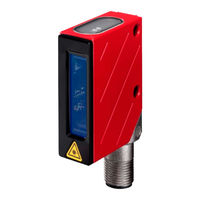
Leuze electronic BCL 8 S M 100 Manual (68 pages)
Barcode Reader with Integrated Decoder
Brand:
Leuze electronic
| Category:
Barcode Reader
| Size: 3.49 MB
Table of Contents
Table of Contents
2
1 General Information
5
Explanation of Symbols
5
Declaration of Conformity
5
2 Safety Notices
6
Safety Standards
6
Approved Purpose
6
Working Safely
7
Figure 2.1: Example for the Attachment of the Sticky Labels with Warning Notices
8
3 Description
9
The BCL 8 Barcode Reader
9
Figure 3.1: Device Construction of the BCL 8
9
Stand Alone Operation
10
Daisy Chain Network
10
4 Specifications
11
General Specifications BCL 8
11
Table 4.1
11
Technical Data
11
LED Indicators
12
Table 4.1
12
Dimensioned and Connection Drawings
13
Figure 4.1: Dimensioned Drawing BCL 8 S M
13
Figure 4.2: Dimensioned Drawing BCL 8 S M
14
Optical Data
15
Type Overview
15
Type Overview - M-Optics
15
Table 4.3
15
Type Overview - N-Optics
15
Reading Fields
16
Figure 4.3: Reading Field of BCL 8 S M
16
Figure 4.4: Reading Field of BCL 8 S N
17
5 Accessories / Order Codes
18
Accessories Overview
18
Table 5.1
18
Connector Unit MA 8.1
19
Figure 5.1: Photo and Dimensioned Drawing of the MA 8.1 Connector Unit
19
Electrical Connection MA 8.1
20
Figure 5.2: Electrical Connection MA 8.1
20
MA 8.1 - PWR in HOST/RS 232 - Voltage Supply and RS 232
21
MA 8.1 - SW IN/OUT - Switching Input and Switching Output
21
Figure 5.2: MA 8.1 - Pin Assignment PWR in HOST/RS 232
21
Figure 5.3: MA 8.1 - Pin Assignment SW IN/OUT
21
Figure 5.4: Connection of the Switching Input/Output of the MA 8.1
22
MA 8.1 - BCL - Connecting the BCL 8 to the MA 8.1
23
Figure 5.5: MA 8.1 - Pin Assignment BCL
23
Connector Unit MA 8-01
24
Figure 5.6: Pin Assignment MA 8-01
24
MA 8-01 - PWR in HOST/RS 485 - Voltage Supply and RS 485
25
Figure 5.7: MA 8-01 - Pin Assignment PWR in HOST/RS 485
25
MA 8-01 - SW IN/OUT - Switching Input and Switching Output
26
Figure 5.8: MA 8-01 - Pin Assignment SW IN/OUT
26
MA 8-01 - BCL - Connecting the BCL 8 to the MA 8-01
27
Figure 5.1: Electrical Connection MA 8-01
27
Figure 5.9: MA 8-01 - Pin Assignment BCL
27
Termination of the RS 485 Interface
28
Figure 5.1: Termination of the RS 485 Interface in the MA 8-01
28
Mounting Accessories
29
Figure 5.2: Mounting Devices for the BCL 8
29
6 Installation
30
Storage, Transportation
30
Figure 6.1: BCL 8 Device Name Plate
30
Mounting
31
Figure 6.2: BCL 8 Mounting Example
31
Device Arrangement
32
Figure 6.3: Definition of the BCL 8 Reading Angles
32
Connection
33
Connecting the BCL 8
33
Figure 6.4: BCL 8 Pin Assignment
33
Table 6.1
33
Wiring Description BCL 8
33
Connecting the Switching Input/Output
34
Figure 6.5: Switching Input for BCL 8 Connection Version 1 (Standard Setting)
34
Figure 6.6: Switching Input for BCL 8 Connection Version 2 (Setting "Inverted")
34
Figure 6.7: Switching Output BCL 8
35
Line Lengths
36
Disassembling, Packing, Disposing
36
7 Commissioning
37
Measures to be Performed Prior to the Initial Commissioning
37
Function Test
37
Setting the Parameters
38
Parameter Sets
38
Service Operating Mode
39
Figure 7.1: Barcode Label "Service
39
Figure 7.2: Connecting the RS 232 Interface to a PC or Terminal
39
8 Operation
40
Display Elements
40
Error Handling
41
9 Communicating with the Device
42
Installing the Bclconfig Software
42
Figure 9.1: Installation Window
42
Figure 9.2: Installation Directory
43
Figure 9.3: BCL 8 Configuration Software
43
10 Important Parameters
44
Decode Tab
44
Figure 10.1: Decode Tab
44
10.1.1 Properties Window - Decode Tab
45
Figure 10.2: Standard Settings for the Properties Window - Decode Tab
45
Output Tab
46
Figure 10.3: Output Tab
46
Control Tab
47
Figure 10.4: Control Tab
47
Host Interface Tab
48
Figure 10.5: Host Interface Tab
48
10.4.1 Properties Window - Host Interface Tab
49
Figure 10.6: Standard Settings for the Properties Window - Host Interface Tab
49
Reference Code Tab
50
Figure 10.7: Reference Code Tab
50
Sensor Tab
51
Figure 10.8: Sensor Tab
51
Laser Tab
52
Figure 10.9: Laser Tab
52
Figure 10.10: Autoreflact Wizard
53
Switch Tab
54
Figure 10.11: Switch Tab
54
11 Online Commands
55
Overview of Commands and Parameters
55
11.1.1 General 'Online' Commands
56
11.1.2 'Online' Commands for System Control
62
11.1.3 'Online' Commands for Parameter Set Operations
63
12 Maintenance
66
General Maintenance Information
66
Repairs, Servicing
66
Diagnostics and Troubleshooting
67
Example Barcode Label Types
68
Figure 12.1:Example Barcode Label Types
68
Advertisement
Advertisement
Related Products
Leuze electronic BCL 8 S M 550
Leuze electronic BCL 8 S M 102
Leuze electronic BCL 8 S M 552
Leuze electronic BCL 34 S M 100 H
Leuze electronic MA 10
Leuze electronic BCL 8 S 2 Series
Leuze electronic BCL 8 Series
Leuze electronic BCL 8 S N 100
Leuze electronic BCL 8 S N 552
Leuze electronic BCL 8 S N 550
Leuze electronic Categories
Accessories
Barcode Reader
Measuring Instruments
Security Sensors
Scanner
More Leuze electronic Manuals
Login
Sign In
OR
Sign in with Facebook
Sign in with Google
Upload manual
Upload from disk
Upload from URL