Sign In
Upload
Manuals
Brands
Juniper Manuals
Network Router
PTX3000
Juniper PTX3000 Manuals
Manuals and User Guides for Juniper PTX3000. We have
4
Juniper PTX3000 manuals available for free PDF download: Features Manual, Hardware Manual, Quick Start Manual
Juniper PTX3000 Features Manual (506 pages)
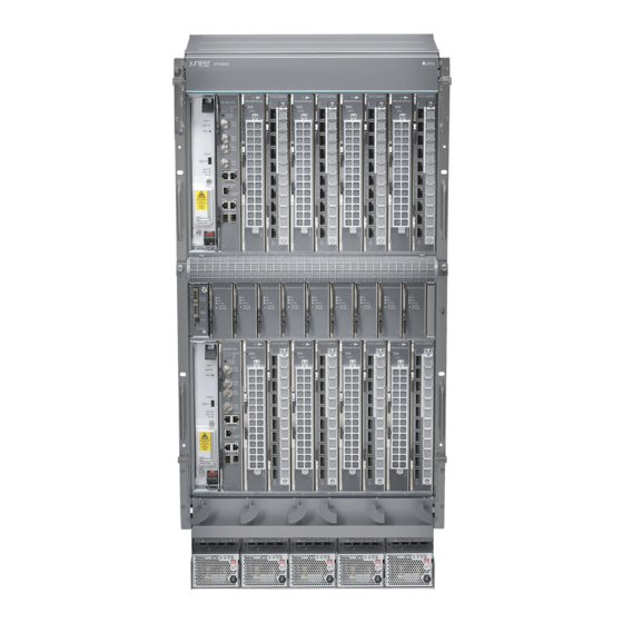
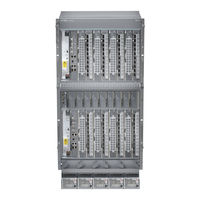
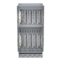
Packet Transport Router Integrated Photonic Line System
Brand:
Juniper
| Category:
Network Router
| Size: 2.78 MB
Table of Contents
Table of Contents
3
About the Documentation
11
Documentation and Release Notes
11
Using the Examples in this Manual
11
Merging a Full Example
12
Merging a Snippet
12
Documentation Conventions
13
About the Documentation
13
Table 1: Notice Icons
13
Table 2: Text and Syntax Conventions
13
Documentation Feedback
15
Requesting Technical Support
15
Self-Help Online Tools and Resources
15
Opening a Case with JTAC
16
Overview
17
Understanding the PTX3000 Integrated Photonic Line System Architecture and Configuration
17
Understanding Optical Supervisory Channel Communication in the
17
Chapter 1 Understanding the PTX3000 Integrated Photonic Line System Architecture and Configuration
19
Integrated Photonic Line Card Base and Expansion Module Overview
19
Overview
20
Configuring, Managing, and Monitoring the IPLC
20
Junos os CLI
20
Figure 1: IPLC Point-To-Point Configuration
20
Junos Space Connectivity Services Director
21
Snmp
21
Optical Supervisory Channel
21
High Availability, Resiliency, and Integrity
21
Usability, Serviceability, Security and Troubleshooting
21
Performance Monitors
21
Understanding the Integrated Photonic Line Card Architecture
22
Architecture Overview
22
Two-Degree Node
23
Functional Component Overview
23
IPLC Base Module Functional Components
23
Figure 2: Combined Functions of the IPLC Base and Expansion Modules
23
IPLC Expansion Module Functional Components
24
Understanding How to Configure the Integrated Photonic Line Card
25
Understanding the Front Panel Connections
25
Recommended Slot Placement
25
Understanding How to Configure Wavelengths on the IPLC Ports
26
Understanding How to Configure the Wavelength Operational Mode
26
Chapter 2 Understanding Optical Supervisory Channel Communication in the Amplifier Chain
27
Understanding Optical Supervisory Channel Communication in the Amplifier
27
Chain
27
Understanding the Functional Components of the Optical Inline
27
Amplifier
27
Understanding How the Optical ILA Is Managed and Controlled
28
Figure 3: Functional Overview of Optical Inline Amplifier
28
Figure 4: Management, Control and Communication of the Optical Inline Amplifier
29
SNMP Management Overview and Configuration
29
Os Cli
30
Table 3: Summary of Optical ILA Configuration Capabilities in Junos os CLI
30
Chain
31
Understanding How to Configure the OSC Using the Junos os CLI
31
Configuring Performance Monitor Thresholds
33
Integrated Photonic Line Card and Optical Inline Amplifier Configuration
33
Chapter 3 Configuring Integrated Photonic Line Card Nodes
35
Increasing the Channel Capacity of the Node
35
Configuring a Two-Degree Node for Express Traffic
37
Ports
38
Chapter 4 Configuring and Managing Express Traffic on Two-Degree IPLC Nodes
41
Bypassing a Wavelength
41
Chapter 5 Switchingwavelengthson Theiplctoopticalinterfaces Inalocalor
43
Remote Chassis
43
Switching a Wavelength to an Optical Interface in the same Chassis
43
Switching a Wavelength to an Optical Interface on a Remote Chassis
44
Configuring the Integrated Photonic Line Card to Switch Wavelengths to Local or Remote Optical Interfaces
45
Switching a Wavelength to an Optical Interface in the same Chassis
46
Switching a Wavelength to an Optical Interface on a Remote Chassis
47
Chapter 6 Configuring the Optical Supervisory Channel in the Amplifier Chain When Using the Optical Inline Amplifier
49
PTX3000 Integrated Photonic Line System
49
Configuring the Anchor IPLC of the Amplifier Chain
50
Configuring the IP Address of the Anchor IPLC
51
Configuring the MAC Address of the Anchor IPLC
52
Configuring the Optical ILA Identification Number
53
Configuring the IP Address of an Optical Inline Amplifier
55
Configuring Optical ILA Authentication through the Junos os CLI
56
Upgrading the Optical Inline Amplifier from the Junos os CLI
57
Chapter 7 Configuring Performance Monitor Thresholds
61
Enabling and Configuring Thresholds on the Integrated Photonic Line Card Performance Monitors
61
Table 4: IPLC Optical Performance Monitors
61
Table 5: IPLC Threshold Crossing Alert Minimum and Maximum Values
62
Enabling and Configuring Thresholds on the Optical Inline Amplifier Performance
67
Monitors
67
Table 6: Optical ILA Performance Monitors
68
Table 7: Optical ILA Threshold Crossing Alert Minimum and Maximum
69
Example Configurations
73
Example: Configuring the PTX3000 Integrated Photonic Line System in a Metro Linear Packet Optical Network
73
Chapter 8 Example: Configuring the PTX3000 Integrated Photonic Line System in
73
Example: Configuring the PTX3000 Integrated Photonic Line System in a Metro Linear Packet Optical Network
75
Configuration
75
Metro Linear Packet Optical Network
75
Figure 5: IPLC in Metro Linear Packet Optical Deployment
76
Table 8: Example Configuration Summary
78
Chapter 9 Example: Configuring the Optical Supervisory Channel
89
Example: Configuring the Optical Supervisory Channel for the Integrated Photonic Line System and Optical Inline Amplifier
89
Figure 6: Example Topology and Configuration
90
Chapter 10 Troubleshooting and Maintenance
97
Enabling or Disabling Erbium-Doped Fiber Amplifiers
97
Enabling or Disabling the Optical Supervisory Channel Laser
98
Resetting an Optical Inline Amplifier through the Junos os CLI
99
Configuration Statements and Operational Commands
101
Configuration Statements
101
Chapter 11 Configuration Statements
103
Amplifier-Chain (IPLC)
104
Expansion-Card (IPLC)
106
Express-In (IPLC)
108
Fpc (M320, T320, T640 and PTX Series Routers)
110
Ila-Options
112
Table 9: Optical ILA EDFA Threshold Crossing Alerts
114
Table 10: Optical ILA OSC Threshold Crossing Alerts
115
Table 11: Optical ILA VOA Threshold Crossing Alerts
115
Optical-Options (IPLC)
116
Switch (IPLC)
118
Tca (IPLC)
120
Table 12: IPLC Optical Performance Monitors
120
Table 13: IPLC Threshold Crossing Alert Minimum and Maximum Values
122
Wavelength (IPLC)
126
Table 14: IPLC Port Number, Wavelength, and Frequency Mapping
127
Wss-Express-In (IPLC)
131
Chapter 12 Operational Commands
133
Clear Chassis Fpc Optical-Properties
134
Show Chassis Fpc Optical-Properties Alarms
135
Table 15: Alarm Descriptions
135
Table 16: Show Chassis Fpc Optical-Properties Alarms Output Fields
136
Show Chassis Fpc Optical-Properties Edfa
138
Table 17: Show Chassis Fpc Optical-Properties Edfa Output Fields
138
Show Chassis Fpc Optical-Properties Mfg-Info
140
Table 18: Show Chassis Fpc Optical-Properties Mfg Info Output Fields
140
Show Chassis Fpc Optical-Properties Ocm
142
Table 19: Show Chassis Fpc Optical-Properties Ocm Output Fields
142
Show Chassis Fpc Optical-Properties Pm-Current
144
Table 20: Show Chassis Fpc Optical-Properties Pm-Current Output Fields
144
Show Chassis Fpc Optical-Properties Pm-Currentday
147
Table 21: Show Chassis Fpc Optical-Properties Pm-Currentday Output Fields
147
Show Chassis Fpc Optical-Properties Pm-Interval
150
Table 22: Show Chassis Fpc Optical-Properties Pm-Interval Output Fields
150
Show Chassis Fpc Optical-Properties Pm-Previousday
153
Table 23: Show Chassis Fpc Optical-Properties Pm-Previousday Output Fields
153
Show Chassis Fpc Optical-Properties Status
156
Table 24: Show Chassis Fpc Optical-Properties Status Output Fields
156
Show Chassis Fpc Optical-Properties Topology
158
Table 25: Show Chassis Fpc Optical-Properties Topology Output Fields
158
Show Chassis Hardware
160
Table 26: Routing Engines Displaying DIMM Information
164
Table 27: Show Chassis Hardware Output Fields
169
Show Chassis Environment Fpc
401
Table 28: Show Chassis Environment Fpc Output Fields
405
Show Chassis Environment Monitored
450
Table 29: Show Chassis Environment Monitored Output Fields
451
Request Chassis Fpc Optical-Module Firmware-Upgrade
472
Request Chassis Fpc Optical-Module Amplifier-Chain Ila Firmware-Upgrade
473
Request Chassis Fpc Optical-Module Amplifier-Chain Ila Soft-Reset
474
Request Chassis Fpc Optical-Module Amplifier-Chain Ila Hard-Reset
475
Show Chassis Fpc Optical-Properties Amplifier-Topology
476
Table 30: Show Chassis Fpc Optical-Properties Amplifier-Topology Output
476
Show Chassis Fpc Optical-Properties Amplifier-Chain Ila Summary
477
Table 31: Show Chassis Fpc Optical-Properties Amplifier-Chain Ila Summary Output
477
Table 32: Show Chassis Fpc Optical-Properties Amplifier-Chain Ila Edfa Output
480
Table 33: Show Chassis Fpc Optical-Properties Amplifier-Chain Ila Osc Output
484
Table 34: Show Chassis Fpc Optical-Properties Amplifier-Chain Ila Voa Output
486
Table 35: Show Chassis Fpc Optical-Properties Amplifier-Chain Ila Alarms Output
488
Table 36: Alarm Descriptions
489
Table 37: Show Chassis Fpc Optical-Properties Pm-Current Output Fields
494
Table 38: TCA Descriptions
495
Output Fields
497
Table 39: Show Chassis Fpc Optical-Properties Amplifier-Chain Ila Pm-Currentday
497
Table 40: TCA Descriptions
498
Table 41: Show Chassis Fpc Optical-Properties Amplifier-Chain Ila Pm-Interval
500
Table 42: TCA Descriptions
501
Table 43: Show Chassis Fpc Optical-Properties Amplifier-Chain Ila Pm-Previousday
504
Table 44: TCA Descriptions
505
Advertisement
Juniper PTX3000 Hardware Manual (174 pages)
Optical Inline Amplifier Hardware Guide
Brand:
Juniper
| Category:
Chassis
| Size: 2.92 MB
Table of Contents
Table of Contents
3
About the Documentation
9
Documentation and Release Notes
9
Using the Examples in this Manual
9
Merging a Full Example
10
Merging a Snippet
11
Documentation Conventions
11
Documentation Feedback
14
Requesting Technical Support
14
Self-Help Online Tools and Resources
15
Creating a Service Request with JTAC
15
1 Overview
16
Optical ILA System Overview
17
Optical Inline Amplifier Description
17
Front Panel
18
FRU Panel
19
Optical ILA Hardware Component Overview
19
Optical ILA Component Redundancy
20
Optical ILA Field-Replaceable Units
20
Optical ILA Chassis
21
Optical ILA Chassis Description
22
Optical ILA Front Panel and FRU Panel
22
Front Panel
22
FRU Panel
23
Optical ILA Chassis Status Leds
24
Optical ILA Management Panel
26
Optical ILA Management Port Leds
28
Optical ILA Cooling System Description
29
Fan Modules
30
Optical ILA Power System
31
Optical ILA AC Power Supply Description
31
Optical ILA DC Power Supply Description
32
Optical ILA Power Supply Leds
34
Optical ILA AC Power Specifications
36
Optical ILA AC Power Cord Specifications
36
Optical ILA DC Power Specifications
37
Optical ILA DC Power Cable and Lugs Specifications
38
DC Power Cables
38
DC Power Connector
39
Optical ILA Chassis Grounding Cable and Lug Specifications
39
2 Site Planning, Preparation, and Specifications
41
Optical ILA Site Preparation Checklist
42
Optical ILA Site Guidelines and Requirements
43
Optical ILA Environmental Requirements and Specifications
44
Optical ILA Clearance Requirements for Airflow and Hardware Maintenance
45
Optical ILA Physical Specifications
46
Optical ILA Rack Requirements
46
Rack Requirements for the Optical ILA
46
Optical ILA Cabinet Requirements
47
Optical Specifications for the Optical ILA
48
Optical ILA Management Cable Specifications and Pinouts
49
Cable Specifications for Console and Management Connections for the Optical ILA
49
Management Port Connector Pinouts for the Optical ILA
50
Console Port Connector Pinouts for the Optical ILA
51
3 Initial Installation and Configuration
52
Overview of Installing the Optical ILA
53
Unpacking and Mounting the Optical ILA
54
Unpacking the Optical ILA
54
Follow the Instructions in "Unpacking and Mounting the Optical ILA
54
Mounting an Optical ILA in a Rack or Cabinet
55
Before You Begin Mounting the Optical ILA
56
Mounting the Optical ILA
57
Connecting the Optical ILA to External Devices
58
Connecting the Optical ILA to a Management Ethernet Device
58
Connecting the Optical ILA to a Management Console
59
Connecting the Optical ILA to the Network and External Devices
60
Connecting the Optical ILA to Power
61
Connecting the Optical ILA Grounding Cable
62
Connecting AC Power to an Optical ILA
63
Connecting DC Power to an Optical ILA
66
Configuring the Software on the Optical ILA
69
Performing Initial Software Configuration for the Optical ILA
69
Optical ILA Modes of Operation
70
Optical ILA CLI System Commands
71
Optical ILA CLI Show Commands
72
Optical ILA CLI Configuration Commands
78
Optical ILA CLI Upgrade Commands
85
Optical ILA CLI Debug Commands
86
Powering off an Optical ILA
88
4 Maintaining Components
91
Maintaining the Optical ILA Cooling System
92
Removing a Fan Module from an Optical ILA
92
Installing a Fan Module in an Optical ILA
93
Maintaining Power Supplies
95
Removing a Power Supply from an Optical ILA
95
Installing a Power Supply in an Optical ILA
97
Maintaining the Optical ILA Fiber-Optic Cables
99
Disconnect a Fiber-Optic Cable
99
Connect a Fiber-Optic Cable
100
How to Handle Fiber-Optic Cables
101
Removing an Optical ILA from a Rack or Cabinet
102
5 Troubleshooting Hardware
104
Troubleshooting the Optical ILA
105
Troubleshooting Resources Overview
105
Optical ILA Alarm Messages Overview
105
6 Contacting Customer Support and Returning the Chassis or Components
111
Returning the Optical ILA Chassis or Components
112
Contacting Customer Support
112
Locating the Serial Number on an Optical ILA Chassis or Component
113
Listing the Chassis and Component Details by Using the CLI
113
Locating the Chassis Serial Number ID Label on an Optical ILA
115
Locating the Serial Number ID Labels on FRU Components
115
How to Return a Hardware Component to Juniper Networks, Inc
116
Guidelines for Packing Hardware Components for Shipment
117
Packing an Optical ILA Chassis or Component for Shipping
118
Packing an Optical ILA for Shipping
118
7 Safety and Compliance Information
120
General Safety Guidelines and Warnings
122
Definitions of Safety Warning Levels
123
Fire Safety Requirements
126
Fire Suppression
126
Fire Suppression Equipment
126
Qualified Personnel Warning
127
Warning Statement for Norway and Sweden
128
Installation Instructions Warning
128
Chassis and Component Lifting Guidelines
129
Restricted Access Warning
130
Rack-Mounting and Cabinet-Mounting Warnings
132
Grounded Equipment Warning
138
Laser Safety Warnings for Class 1M Juniper Networks Devices
139
General Laser Safety Guidelines
139
Class 1M Laser Product Warning
140
Class 1 LED Product Warning
141
Laser Beam Warning
142
Radiation from Open Port Apertures Warning
143
Maintenance and Operational Safety Guidelines and Warnings
144
Battery Handling Warning
145
Jewelry Removal Warning
146
Lightning Activity Warning
148
Operating Temperature Warning
149
Product Disposal Warning
151
General Electrical Safety Guidelines and Warnings
152
Action to Take after an Electrical Accident
153
Prevention of Electrostatic Discharge Damage
153
AC Power Disconnection Warning
155
Optical ILA DC Power Electrical Safety Guidelines
155
DC Power Copper Conductors Warning
157
DC Power Disconnection Warning
158
DC Power Grounding Requirements and Warning
160
DC Power Wiring Sequence Warning
162
DC Power Wiring Terminations Warning
165
Multiple Power Supplies Disconnection Warning
168
Site Electrical Wiring Guidelines for Juniper Networks Devices
169
Distance Limitations for Signaling
169
Radio Frequency Interference
169
Electromagnetic Compatibility
169
Agency Approvals and Compliance Statements
170
Optical ILA Agency Approvals
171
Compliance Statements for EMC Requirements
172
Canada
172
European Community
172
Israel
172
Japan
173
United States
173
Compliance Statements for Environmental Requirements
173
Compliance Statements for NEBS
173
Optical ILA Compliance Statements for Acoustic Noise
174
Juniper PTX3000 Quick Start Manual (48 pages)
Packet Transport Router
Brand:
Juniper
| Category:
Network Router
| Size: 4 MB
Table of Contents
Table of Contents
1
Quick Start Description
3
Step 1: Prepare the Site for the PTX3000
3
Rack-Mounting Requirements
3
Tools Required to Unpack and Install the PTX3000
6
Step 2: Unpack the PTX3000
7
Step 3: Install the PTX3000 Mounting Hardware
7
Install Cage Nuts, if Needed
7
Install the Mounting Shelf
8
Step 4: Install the PTX3000
9
Step 5: Connect the PTX3000 Grounding Cable
15
Step 6: Connect External Devices and PIC Cables to the PTX3000
17
Connect the PTX3000 to a Console or Auxiliary Device
17
Connect the PTX3000 to a Network for Out-Of-Band Management
18
Connect PIC Cables to the PTX3000
20
Step 7: Connect the PTX3000 to Power
23
Connect AC Power to the PTX3000 AC Power Supply Modules
24
Connect Nonredundant AC Power to the PTX3000 AC Power Supply Modules
24
Connect Redundant AC Power to the PTX3000 AC Power Supply Modules
24
Connect DC Power to the PTX3000 DC Power Supply Modules
27
Connect Nonredundant DC Power to the PTX3000 DC Power Supply Modules
27
Connect Redundant DC Power to the PTX3000 DC Power Supply Modules
27
Step 8: Power on the PTX3000
32
Power on the AC-Powered PTX3000
32
Power on the DC-Powered PTX3000
34
Step 9: Install the Front Doors on the PTX3000
36
Step 10: Perform the PTX3000 Initial Software Configuration
37
Enter Configuration Mode
38
Configure User Accounts and Passwords
38
Configure System Attributes
39
Commit the Configuration
40
Safety Warnings
42
PTX3000 Compliance Statements for NEBS
44
Compliance Statements for EMC Requirements
44
Canada
44
European Community
44
Israel
45
Japan
45
United States
45
Junos os Documentation and Release Notes
46
Requesting Technical Support
46
Self-Help Online Tools and Resources
46
Creating a Service Request with JTAC
47
Revision History
48
Advertisement
Juniper PTX3000 Quick Start Manual (37 pages)
Packet Transport Router
Brand:
Juniper
| Category:
Network Hardware
| Size: 2.86 MB
Table of Contents
Table of Contents
1
Quick Start Description
3
Step 1: Prepare the Site for the PTX3000 Packet Transport Router
3
Rack-Mounting Requirements
3
Tools Required to Unpack and Prepare the PTX3000 Packet Transport Router for Installation
5
Step 2: Unpack the PTX3000 Packet Transport Router
5
Step 3: Install the PTX3000 Packet Transport Router Mounting Hardware
5
Install Cage Nuts, if Needed
5
Install the Mounting Shelf
6
Step 4: Install the PTX3000 Packet Transport Router
7
Install the Packet Transport Router by Using a Lift
7
Step 5: Connect the PTX3000 Packet Transport Router Grounding Cable
12
Transport Router
14
Connect the PTX3000 to a Console or Auxiliary Device
14
Connect the PTX3000 to a Network for Out-Of-Band Management
15
Connect PIC Cables to the PTX3000
16
Step 7: Connect the PTX3000 Packet Transport Router to Power
19
Connect DC Power to the PTX3000 DC Power Supply Modules
19
Connect Nonredundant DC Power to the PTX3000 DC Power Supply
19
Modules
19
Connect Redundant DC Power to the PTX3000 DC Power Supply
19
Modules
20
Connect AC Power to the PTX3000 AC Power Supply Modules
24
Connect Nonredundant AC Power to the PTX3000 AC Power Supply
24
Modules
24
Connect Redundant AC Power to the PTX3000 AC Power Supply
24
Step 8: Power on the PTX3000 Packet Transport Router
26
Power on the DC-Powered PTX3000 Packet Transport Router
26
Power on the AC-Powered PTX3000 Packet Transport Router
27
Router
28
Step 10: Perform the PTX3000 Packet Transport Router Initial Software
29
Configuration
29
Enter Configuration Mode
29
Configure User Accounts and Passwords
30
Configure System Attributes
30
Commit the Configuration
31
Safety Warnings
33
Compliance Statements for NEBS
35
Compliance Statements for EMC Requirements
35
Canada
35
European Union
35
Junos os Documentation and Release Notes
35
Requesting Technical Support
36
Self-Help Online Tools and Resources
36
Opening a Case with JTAC
36
Revision History
37
Advertisement
Related Products
Juniper PTX5000
Juniper PTX10002-60C
Juniper PTX10003-160C
Juniper PTX10003-80C
Juniper PTX1000
Juniper PTX10001-36MR
Juniper PTX10004
Juniper PTX10016
Juniper PTX Series
Juniper PTX10004-PREM2
Juniper Categories
Network Router
Switch
Gateway
Software
Network Hardware
More Juniper Manuals
Login
Sign In
OR
Sign in with Facebook
Sign in with Google
Upload manual
Upload from disk
Upload from URL