Sign In
Upload
Manuals
Brands
Johnson Controls Manuals
Control Panel
IFC-3030
Johnson Controls IFC-3030 Manuals
Manuals and User Guides for Johnson Controls IFC-3030. We have
4
Johnson Controls IFC-3030 manuals available for free PDF download: Programming Manual, Operation Manual, Installation Manual, Wiring Manual
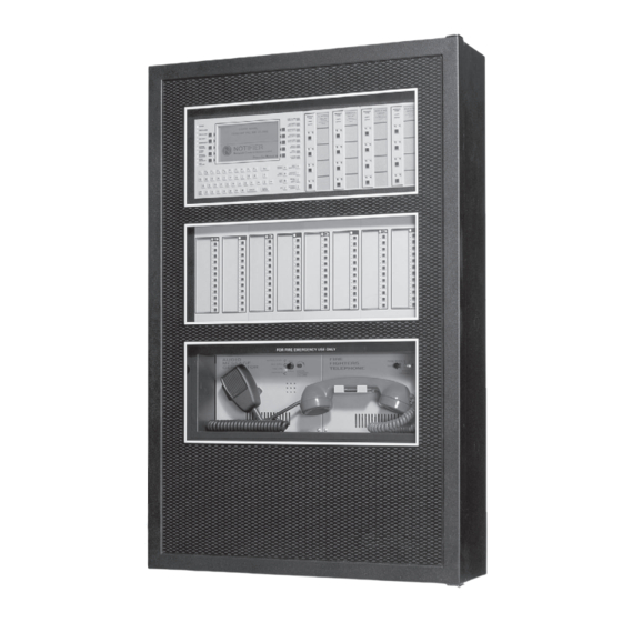
Johnson Controls IFC-3030 Programming Manual (156 pages)
Fire Alarm Control Panel
Brand:
Johnson Controls
| Category:
Control Panel
| Size: 1 MB
Table of Contents
Table of Contents
5
Section 1: General Information
9
About this Manual
9
Supplemental Information
10
Introduction to the Control Panel
11
1: Features
11
Navigating Menu and Programming Screens
11
Basic Procedure
12
Getting Started
12
1: Password Change
12
Section 2: Main Menu
15
Event Counts Display
15
Multiple Event List
15
History Display (History Select Screen)
15
Read Status
16
Program/Alter Status
16
Printer Functions
16
Section 3: Program
17
General Information
17
Panel Program
18
1: Panel Program Menu (1)
18
2: Network Parameters
19
3: Panel Settings
21
4: Panel Timers (Menu 1)
23
5: Panel Timers (Menu 2)
25
6: LCD Programming
26
7: ACS Programming
26
8: Supervision
30
Panel Program Menu (2)
31
1: Password Change
31
2: Weekly Occupancy Schedule
31
3: Remote Display Menu
32
4: Loop Configuration
33
5: Custom Action Message
35
6: Event Logging
36
7: Holiday Menu
36
Point Program
37
1: Detector Point
38
2: Module Point
43
3: Panel Circuit Module
47
4: General Zone
51
5: Releasing Zone
51
6: Logic Zone
52
7: Trouble Zone
55
8: Annunciator Board Label
56
Delete Program
56
Autoprogram Menu
58
1: to Create a New Program
58
2: to Add/Delete Devices from the Program
58
3: Confirmation Screens
59
Section 4: Alter Status
65
Disable/Enable Point Selection
65
Disable/Enable
66
Detector Sensitivity
67
1: Sensitivity Select
67
Clear Verify Counters
69
Clear History
69
Walk Test
70
1: Walk Test Menu
72
2: Walk Test Loops Parameters
73
3: Advanced Walk Test Activation
73
4: Devices Test Selection
74
Program Time/Date
75
Control On/Off Point Select
76
1: Control off
76
2: Control on
77
Section 5: Service Screens
79
Version Information
79
Power-Up Screen
80
Bootloader Screen
81
1: LCD-160 Download Menu
81
2: Loop Download Menu
82
Download Screen
83
Application Corrupt Screen
83
Appendix A: Menu Hierarchy
85
A.1: Screens Overview
85
Appendix B: Releasing Applications
89
B.1: Releasing Zones
89
B.2: NFPA Releasing Applications
90
B.3: Abort Switches
90
B.3.1: ULI Abort Switch
92
B.3.2: IRI Abort Switch
93
B.3.3: NYC Abort Switch
94
B.3.4: AHJ Abort Switch
96
B.3.5: Cross Zones
97
B.3.6: Using Type Codes for Releasing Zones
98
B.4: Miscellaneous
112
B.4.1: Initiating Devices
112
B.4.2: Warning Sounders
112
B.4.3: Auxiliary Control Functions
112
B.4.4: ACS Annunciation
112
Appendix C: Special Zone Outputs
113
C.1: Presignal and Positive Alarm Sequence (PAS)
113
C.1.1: What Is Presignal and PAS
113
C.1.2: Selecting Presignal and PAS Outputs
113
C.2: Coding Functions for Panel Circuit Outputs
114
Appendix D: AWACS™ Applications
115
D.1: AWACS Overview
115
D.2: AWACS Features
115
D.2.1: Drift Compensation and Smoothing
115
D.2.2: Maintenance Warnings - Three Levels
116
D.2.3: Self-Optimizing Pre-Alarm
117
D.2.4: Detector Sensitivity
117
D.2.5: Cooperative Multi-Detector Sensing
118
D.3: Pre-Alarm
118
D.3.1: Definition
118
D.3.2: Alert Level
118
D.3.3: Action Level
119
D.4: Detector Sensitivity Settings
119
D.4.1: How to Select Pre-Alarm and Alarm Sensitivity
119
D.4.2: to Test Detectors Set below 0.50% Obscuration Per Foot
121
D.5: Detector Status Display
121
D.5.1: Detector Maintenance Display
121
D.5.2: Print a Detector Maintenance Report
122
D.5.3: to Interpret a Detector Status Display or Maintenance Report
122
Appendix E: CBE: Zones and Equations
125
E.1: Zones
125
E.2: Equations
126
E.2.1: Arguments
126
E.2.2: Logic Equations
126
E.2.3: Trouble Equations
129
Appendix F: Detector Initialization
131
F.1: Overview
131
F.2: to Replace a Detector with a Different Type of Detector
131
Appendix G: Type Codes
133
G.1: What Are Type Codes
133
G.2: How to Select a Type Code
133
G.3: Type Codes for Input Devices
134
G.3.1: Overview
134
G.3.2: Type Codes for Intelligent Detectors
134
G.3.3: Type Codes for Monitor Modules
135
G.4: Type Codes for Output Devices
136
G.5: Flashscan Codes
137
Appendix H: System Troubles
139
Appendix I: Local Settings
141
I.1: Singapore
141
I.2: Chicago
142
Glossary
143
Index
147
Advertisement
Johnson Controls IFC-3030 Installation Manual (72 pages)
Fire Alarm Control Panel
Brand:
Johnson Controls
| Category:
Control Panel
| Size: 2 MB
Table of Contents
Fcc Warning
3
Installation Precautions
3
Table of Contents
5
Section 1: about this Manual
7
Standards and Other Documents
7
Supplemental Documentation
8
Cautions and Warnings
9
Section 2: System Overview
11
System Description
11
1: Standard Features
11
2: Options
11
3: System Limitations
11
System Components
12
Product Diagram
13
1: Main Power Supply
14
System Cabinets
15
Compatible Equipment
16
Notifier/Johnson Controls Compatible Equipment
16
System Sensor Compatible Equipment
17
Section 3: Installation
19
Preparing for Installation
19
Installation Checklist
19
Mounting a Cabinet
20
Laying out Equipment in Cabinet and Chassis
21
Attaching the CPU & Chassis
22
Mounting Chassis in Backbox
23
1: Memory-Backup Battery
23
Attaching Option Boards
24
Mounting Procedures
24
Attaching Panel Circuit Modules
25
1: Overview
25
2: Mount Expander Boards
26
3: Installing a Multi-Layer Module into the Chassis
26
4: Connecting Expander Row Ribbon Cables
28
Initiating Device Circuits with IZM-8RK/IZE-A
29
1: Style B Field Wiring (up to 8 Style B Idcs)
29
2: Style D Field Wiring
30
Nacs with ICM-4RK⁄ICE-4
31
1: Power Supply Connections
32
Form-C Relays on the CPU
33
Form-C Relays with CRM-4RK/CRE-4
34
Form-C Relays with Auxiliary Relay Module (ARM-4)
35
1: Overview
35
2: Installation
35
3: Field Wiring an Auxiliary Relay Module
36
Notification Appliance Circuit Current Limitations
36
Connecting Specific Option Boards
37
1: Network Control Module
37
2: Loop Control Module, Loop Expander Module
37
Mounting Instructions
37
Setting SLC Loop Number
38
Enabling External Power Supervision
38
Connecting Power Sources and Outputs
41
1: Overview
41
2: Connecting the Power Supply
42
3: Checking AC Power
42
4: Auxiliary Power Supply Connections
42
UL Power-Limited Wiring Requirements
43
ULC Remote Connection Feature
43
Installing Printers
44
1: Printer Installation Sequence
45
2: Configuring the Printer
46
PRN Printer Settings
46
Keltron Printer VS4095/5 Settings
46
Wiring a Signaling Line Circuit (SLC)
47
1: Overview
47
2: Capacity
47
3: Installation
48
Connecting a PC for Programming
48
Section 4: Applications
49
Overview
49
Devices Requiring External Power Supervision
49
NFPA 72 Central or Remote Station Fire Alarm System (Protected Premises Unit)
50
NFPA 72 Proprietary Fire Alarm Systems
51
Fire/Security Applications
52
1: General Operation
52
2: General Security Requirements
52
3: Installing a Security Tamper Switch
53
4: Receiving Unit
53
5: Programming
53
6: Wiring for Proprietary Security Alarm Applications
54
7: Connecting an RKS-S Remote Key Switch
55
8: Single Tenant Security System with Entry/Exit Delay
56
Programming Notes for Figure 4.8
56
9: Security Annunciation
58
Releasing Applications
58
1: Overview
58
2: Programming
58
3: Wiring
59
Connecting a Releasing Device to a M300CJ Module
59
1: Connecting an NBG-12LRA Agent Release-Abort Station
60
Section 5: Testing the System
61
Acceptance Test
61
Periodic Testing and Service
61
Operational Checks
61
Battery Checks and Maintenance
62
Appendix A: Electrical Specifications
63
A.1: Operating Power
63
A.2: SLC Loops
63
A.3: Notification Appliance Circuits
63
A.4: Wire Requirements
63
Appendix B: Canadian Applications
65
B.1: Standalone Application
65
B.2: Local Network Application
65
B.3: Automatic Alarm Signal Silence
65
B.4: Annunciator Applications
65
B.5: Releasing Devices
65
Index
69
Johnson Controls IFC-3030 Wiring Manual (72 pages)
Intelligent Control Panel SLC
Brand:
Johnson Controls
| Category:
Control Panel
| Size: 2 MB
Table of Contents
Table of Contents
5
Section 1: Introduction
8
About this Manual
8
UL 864 Compliance
8
1: Products Subject to AHJ Approval
8
Reference Documentation
9
SLC Overview
11
Polling Protocols
11
Devices
12
1: Monitor/Zone Interface Modules
12
2: Control Modules
12
3: Isolator Modules
12
4: Relay Modules
13
5: Transponders
13
6: Plug-In Detector Bases
13
7: Intelligent Detectors
13
8: Addressable Manual Pull Stations
14
9: RFX Wireless Interface
14
10: ACPS-610/E Addressable Charger/Power Supply
14
11: ACPS-2406 Addressable Charger/Power Supply
15
12: AMPS-24/E Addressable Power Supply
15
SLC Capacity
15
SLC Performance
15
LED Operation
16
Section 2: Wiring Requirements
17
Recommended SLC Wiring
17
Two-Wire SLC - Style 4 (Class B)
18
1: Measuring Loop Resistance
18
2: Measuring Total Wire Length
19
Four-Wire SLC Style 6 & 7 (Class A)
19
1: Measuring Loop Resistance
19
2: Measuring Total Wire Length
20
Control Panel Terminal Blocks
20
1: IFC2-3030 and IFC-3030 with LCM-320, LEM-320
20
2: IFC2-640 with Loop Expander Modules, IFC-320
21
3: IFC-640 with Loop Expander Modules
21
4: Ifc-200
21
5: Ifc-300/Ifc-400
22
6: IFC-1010/IFC-2020 with JLIB-200A or JLIB-400
22
Section 3: Shielded Wire Termination
23
Overview
23
No Conduit
23
Full Conduit
24
Partial Conduit
24
Floating Shield
25
Section 4: SLC Circuits Without Isolators
26
Overview
26
NFPA Style 4 SLC
26
NFPA Style 6 SLC
27
Section 5: SLC Circuits with Isolators
28
Overview
28
Fault Isolator Module
28
1: Wiring an Isolator Module
28
Isolator Detector Bases
29
1: How an Isolator Base Works
29
NFPA Style 4 SLC Using Isolator Modules
30
NFPA Style 6 SLC Using Isolator Modules
31
NFPA Style 7 SLC Using an Isolating Device
32
Section 6: Monitor Modules
33
Description
33
1: Addressable Monitor Module
33
2: Zone Interface Module
33
3: Dual Monitor Module
34
4: Miniature Monitor Module
34
5: M300MJ-4-20 4-20Ma Monitor Module
34
Setting an SLC Address for a Module
35
NFPA Style B IDC Using Monitor Modules
36
NFPA Style D IDC Using Monitor Modules
37
NFPA Style B IDC Using Dual Monitor Modules
38
NFPA Style B IDC Using Zone Interface Modules
39
NFPA Style D IDC Using Zone Interface Modules
40
Section 7: Control Modules
41
Description
41
Wiring a NAC with Addressable Control Modules
41
1: Wiring a Solenoid with the M300CJ-REL
42
Wiring a Style y NAC (Two-Wire) with Addressable Control Modules
43
Wiring a Style Z NAC (Four-Wire) with Addressable Control Modules
44
Connecting a Releasing Device to the Addressable Control Module
45
Section 8: Relay Module
47
Description
47
Wiring the Addressable Relay Module (Form-C Relay)
47
Section 9: Intelligent Detector Bases
48
Description
48
Wiring a Detector Base
48
Wiring an Isolator Base
50
Wiring a Relay Base
50
Wiring a Sounder Base
51
Section 10: Addressable Manual Pull Station
52
Description
52
Wiring a Manual Pull Station
52
Appendix A: Power Considerations
53
A.1: Supplying Power to 24 VDC Detectors and Nacs
53
A.2: Supervising 24 VDC Power
54
A.2.1: Using Type Codes with Built-In Power Supervision on IFC-3030
54
A.2.2: Power Supervision Relay
54
A.2.3: Using the Addressable Control Module Without Relay
56
Appendix B: SLC Surge Suppression
58
B.1: Introduction
58
B.2: Installation
59
B.2.1: Ifc-200
59
B.2.2: Ifc-300, Ifc-400
60
B.2.3: IFC-1010 & IFC-2020 (JLIB-200A or JLIB-400)
61
B.2.4: Ifc-640/E, Ifc-3030
62
Appendix C: Terminal Conversion Charts for V-Type and H-Type Devices
63
C.1: M300Rj
63
Advertisement
Johnson Controls IFC-3030 Operation Manual (76 pages)
Fire Alarm Control Panel
Brand:
Johnson Controls
| Category:
Control Panel
| Size: 0 MB
Table of Contents
Fire Alarm System Limitations
2
Installation Precautions
3
Table of Contents
5
Section 1 General Information
7
About this Manual
7
Supplemental Information
7
Introduction to the Control Panel
8
Operating Features
8
1: the Display/Keypad
10
The Liquid Crystal Display
10
The Keypad
10
Message Formats
12
1: System Normal Screen
12
2: Event Reporting Format
13
Point Events Format
13
System Events Format
14
Navigating Menu and Programming Screens
15
The Main Menu
15
1: Event Counts Display
16
2: more Information
17
3: Multiple Event List
18
4: History Display (History Select Screen)
19
5: Read Status
20
6: Program/Alter Status
20
7: Printer Functions
20
Section 2 Operation of the Control Panel
21
Overview
21
1: System Normal
21
2: Acknowledging an Event
21
Fire Alarm Event
23
1: How the Control Panel Indicates a Fire Alarm
23
2: How to Respond to a Fire Alarm
23
3: Interpreting Type ID Codes
24
System or Point Trouble Event
25
1: How the Control Panel Indicates a System or Point Trouble
25
2: How to Respond to a System or Point Trouble
26
3: Trouble Types
26
Point (Device) Troubles
26
System Troubles
28
4: Interpreting Type ID Codes
29
Pre-Alarm Event
30
1: How the Control Panel Indicates a Pre-Alarm
30
2: How to Respond to a Pre-Alarm Warning
30
3: Interpreting Type ID Codes
31
Security Alarm Event
32
1: How the Control Panel Indicates a Security Alarm
32
2: How to Respond to a Security Alarm
32
3: Interpreting Security Type Codes
33
Supervisory Signal Event
34
1: How the Control Panel Indicates an Active Supervisory
34
2: How to Respond to an Active Supervisory
34
3: How to Interpret Type Codes
35
Disabled Points Event
36
Active Event
37
1: How the Control Panel Indicates an Active Fire Control Point
37
2: How the Control Panel Indicates an Active Non-Fire Point
37
Operation of Special System Timers, Presignal, and PAS
38
1: System (Panel) Timers
38
Alarm Verification Timer (VERIFY TIME)
38
AC Fail Delay Timer
38
Silence Inhibit Timer
38
Auto Silence Timer
38
2: Presignal
38
How the Panel Indicates a Presignal Alarm
39
How to Respond to a Presignal Alarm
39
3: PAS (Positive Alarm Sequence)
39
Section 3 Read Status
41
Point Select Screen
41
Smoke Detector
42
Heat Detector
43
Monitor Module
44
Control Module
44
Panel Input
46
Panel Output
46
General Zone
47
Logic Zone
47
Releasing Zone
48
Special Function Zone
48
Trouble Zone
49
Annunciator
49
Section 4 Viewing and Printing History Information
51
Events History
51
Time and Date Range Selection for All Events
52
Point Range Select for All Events in Range
53
Section 5 Printing Reports
55
Printer Functions Screen
55
Print Programming Menu Screen
56
Print Programming Menu Screen (2)
58
Active Points Report Screen
59
Installed Points Report Screen
59
Appendix A Software Type ID Codes
63
Appendix B Releasing Zones
67
Advertisement
Related Products
Johnson Controls IFC-300
Johnson Controls IFC-320
Johnson Controls IFC-320E
Johnson Controls IFC-320C
Johnson Controls IFC-200
Johnson Controls IFC-400
Johnson Controls IFC-1010
Johnson Controls IFC-2020
Johnson Controls IFC-640E
Johnson Controls IFC2-640
Johnson Controls Categories
Controller
Air Conditioner
Thermostat
Control Unit
Irrigation System
More Johnson Controls Manuals
Login
Sign In
OR
Sign in with Facebook
Sign in with Google
Upload manual
Upload from disk
Upload from URL