Sign In
Upload
Manuals
Brands
JLG Manuals
Forklifts
TOUCAN 10E
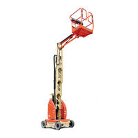
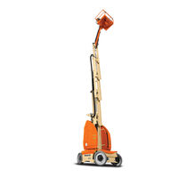
JLG TOUCAN 10E Manuals
Manuals and User Guides for JLG TOUCAN 10E. We have
3
JLG TOUCAN 10E manuals available for free PDF download: Service And Maintenance Manual, Operation And Safety Manual
JLG TOUCAN 10E Service And Maintenance Manual (191 pages)
Brand:
JLG
| Category:
Boom Lifts
| Size: 15 MB
Table of Contents
Table of Contents
5
Section a - Introduction - Maintenance Safety Precautions
3
General
3
Bhydraulic System Safety
3
Cmaintenance
3
Table of Contents
5
Section 1. Operating Specifications
16
Operating Specifications
16
DIMENSIONAL Data
16
Performance Data
17
Capacities
18
Components Data
18
Batteries
18
Electric Pump / Electric Motor Assembly
18
Drive Motor Assembly
18
Swing Motor
19
Cylinders
19
Tires
19
Major Components Weights
20
Lubrication
21
Hydraulic Oil
21
Lubrication Chart
22
Lube Specifications
23
Torque Requirements
23
Serial Number Locations
24
Section 2 - General Service Information
27
Machine Preparation, Inspection and Maintenance
27
General
27
Preparation, Inspection and Maintenance
27
Pre-Start Inspection
27
Pre-Delivery Inspection and Frequent Inspection
27
Annual Machine Inspection
27
Preventative Maintenance
27
Preventive Maintenance and Inspection Schedule
28
Servicing and Maintenance Guidelines
31
General
31
Safety and Workmanship
31
Cleanliness
32
Components Removal and Installation
32
Component Disassembly and Reassembly
32
Pressure-Fit Parts
32
Bearings
32
Care and Installation of Teflon Coated Bushings
32
Bolt Usage and Torque Application
33
Hydraulic Lines and Electrical Wiring
33
Hydraulic System
33
Welding on Work Platform
34
Lubrication
34
Battery
34
Lubrication Information
34
Hydraulic System
34
Lubrication Specifications
34
Hydraulic Oil
34
Changing Hydraulic Oil
34
Pressure Relief Valve
34
Section 3 - Theory of Operation
38
Overview
38
Modes of Operation
38
Ground Mode
38
Platform Mode
38
Can Communications
38
Joysticks
40
Traction
40
Pump/Structure Movements
41
Lift Up/Down
41
Hydraulic Pump Electric Schematic
41
Mast Lift System - Basic Schematic
41
Swing
42
Steer
43
Interlocks
43
Steer System - Basic Schematic
43
Personality Settings and Calibration
44
Section 4 - Chassis Mounted Components
47
Drive Motors
47
Brake - Dust Cleaning
47
Brake Disassembly
47
Brake Disk Wear Checking
47
Dust Cleaning
47
Brake Assembly
48
Drive Motor Assembly Removal
48
Drive Motor Assembly Installation
49
Wheel Motor Disassembly
49
Drive Motor Installation
49
Motor Disassembly
49
Wheel Motor Assembly
50
Rotor Disassembly
50
Encoder Disassembly
50
Encoder Assembly
50
Rotor Assembly
51
Oil Filling
52
Wheels and Tires
52
Tire Wear and Damage
52
Wheel and Tire Replacement
52
Wheel Installation
52
Steering Linkage
53
Steer Cylinder
54
Steering Linkage - Spindle/Hub Assembly
54
Hoses and Cables Routing
55
Front Wheel Hub
55
Section 5 - Turntable and Vertical Mast
57
Swing Bearing
57
Swing Bearing Attach Bolts Check
57
Swing Bearing Lubrication
57
Replacement of Swing Bearing
58
Counterweight Removal (T10E/T26E)
58
Counterweight Removal (T8E/T20E)
59
Mast Assembly Lifting
59
Mast Section #1 Set on Blockings
60
Bearing Alignment T10E/T26E
60
Bearing Alignment T8E/T20E
60
Swing Motor
62
Mast Profile Lubrication
63
Rollers
63
Inspection
63
Removal and Installation
63
Mast Profiles Lubrication
63
Roller Assembly
64
Roller Removal
64
Roller Installation
64
Mast and Rollers Setting
65
Introduction
65
Procedure
65
Top Rollers Mast Configuration
65
Top Rollers Mast Centering
66
(Top View-Mast Lowered)5-10
66
Bottom Rollers Mast Configuration
66
Bottom Rollers Mast Centering
67
(Bottom View - Mast Raised)5-11
67
Mast Vertical Alignment
67
Top and Bottom Rollers
68
Lifting Chains
69
Safety Accessories and Tooling
69
Lubrication
69
Lifting Chains Inspection
70
Lifting Chains Removal and Installation
71
Chains Stages and Attachments Description - T10E/T26E
71
Chains Stages and Attachments Description (T8E/T20E)
72
Second Chain Stage (T8E/T20E)5-19
75
Chain Tension Adjustment
79
Chains Tension Control
79
Pulley - Pulley Support
80
Pulley Inspection
80
Removal and Installation
81
Mast Cylinder Removal and Installation
81
Mast Cylinder Removal
81
Mast Cylinder Disassembly
82
Mast Cylinder Installation
82
Section 6 - Jib and Platform
83
Platform
83
Platform Removal
83
Platform Installation
83
Overlaod System
83
Bevel Washers Lubrication
83
Bevel Washer Lubrication
83
Overload System Verification
84
Overload System Setting
84
Jib Cylinder Removal and Installation
84
Jib Cylinder Removal
84
Jib Cylinder Removal - Figure 1 of 2
84
Jib Cylinder Removal - Figure 2 of 2
84
Jib Cylinder Disassembly
85
Jib Cylinder Installation
85
Section 7 - Hydraulics
88
Hydraulic Tank
88
Oil Level
88
Oil Level if Decal Is Missing
88
Adding Oil to the System
88
Tank Draining/Cleaning
88
Tank Filling
89
Hydraulic Filter Replacement
89
Oil Filter Replacement
89
Hydraulic Power Unit
90
Ports Identification
90
Hydraulic Lines Connections
91
Proportional Pressure Relief Valve
91
Air Bleeding
91
Flow Directional Valve
92
Steer Valve
92
Swing Valve
92
Swing Motor By-Pass Valve
92
Electric Motor
92
Terminal Tightening
92
Dust Cleaning
92
Swing Motor
93
Ports Identification
93
Swing Motors
93
Cylinders Holding Valves
94
Mast Cylinder Holding Valve
94
Jib Cylinder Holding Valve
95
Mast Cylinder Holding Valve - Schematic/Exploded View
95
Cylinder Repair
96
Disassembly
97
Inspection
97
Assembly
98
Section 8 - Control Components
101
Control Components Overview
101
Control Components Location - T8E/T20E
101
Control Components Location - T10E/T26E
102
Control Components - Service
103
Battery Maintenance and Safety Practices
103
Main Power Contactor Relay
106
Power Fuse
106
Mast Elevation Limit Switches
107
Chain Slack Sensor
108
Overload Sensor (if Equipped)
110
Drive Orientation Switch
110
Overload Sensor
110
Steering Sensor
111
Tilt Sensor
111
Ground Alarm
113
Warning Beacon
113
Descent/Motion Alarm (Optional)
114
Traction System
115
Common Traction System Difficulties
115
Power Module
116
Removal
116
Installation
117
Power Module Electrical Evaluation
118
Ground Control Station
120
Membrane Panel
120
Printed Circuit Board (PCB) Replacement
120
Platform Control Station
121
Printed Circuit Board (PCB) Replacement
121
Upper Control Box - Component Replacement
121
Upper Control Box - Components Evaluation
122
Section 9 - Jlg Control System
126
Hand Held Analyzer
126
To Connect the Hand Analyzer
126
Using the Analyzer
126
Changing the Access Level of the Hand Held Analyzer
127
Machine Setup
128
Analyzer Screen Layout
129
Machine Setup Programming Information
134
Calibration Instructions
135
Calibrating Steering Sensor
135
Calibrating Overload System
135
Calibrating the Joysticks
136
Calibrating the Pressure Relief Valve
136
Machine Personality - Adjustment Settings
137
System Test
140
Section 10 - Diagnostic Trouble Codes Section 10. Diagnostic Trouble Codes 10.1 Introduction
143
Section 10 - Diagnostic Trouble Codes
143
Introduction
143
Dtc Index
143
Dtc Check Tables
144
Help Comments
144
Power-Up
145
Platform Controls
145
Ground Controls
146
Function Prevented
150
Line Contactor Open Circuit
150
Line Contactor Short Circuit
151
Ground Output Driver
151
Thermal Limit
155
Battery Supply
156
Transmission and Drive System
157
Communication
158
Accessory
159
Electric Motor
159
Tilt Sensor
160
Platform Load Sense
161
Steering/Axle
161
Safety System Override
162
Hardware
162
Section 11 - General Electrical Information & Schematics
168
General
168
Multimeter Basics
168
Grounding
168
Backprobing
168
Min/Max
168
Polarity
168
Scale
168
Voltage Measurement
168
Resistance Measurement
169
Continuity Measurement
169
Current Measurement
170
Checking Switches
170
Basic Check
170
Limit Switches
170
Automatic Switches
171
Switch Wiring - Low Side, High Side
171
Applying Silicone Dielectric Compound to Electrical Connections
171
AMP Connector
172
Applying Silicone Dielectric Compound to AMP Connectors
172
Assembly
172
Disassembly
174
Wedge Lock
174
Service - Voltage Reading
174
Deutsch Connectors
176
DT/DTP Series Assembly
176
DT/DTP Series Disassembly
176
HD30/HDP20 Series Assembly
177
HD30/HDP20 Series Disassembly
177
Advertisement
JLG TOUCAN 10E Service And Maintenance Manual (156 pages)
Brand:
JLG
| Category:
Boom Lifts
| Size: 8 MB
Table of Contents
Section a - Introduction - Maintenance Safety Precautions Revison Log
5
Section a - Introduction - Maintenance Safety Precautions
3
General
3
Bhydraulic System Safety
3
Cmaintenance
3
Table of Contents
5
Section 1 - Operating Specifications
15
Operating Specifications
15
DIMENSIONAL Data
15
Performance Data
16
Capacities
16
Components Data
17
Batteries
17
Drive Motor Assembly
17
Electric Pump / Electric Motor Assembly
17
Swing Motor
17
Cylinders
18
Tires
18
Major Components Weights
18
Lubrication
19
Hydraulic Oil
19
Lubrication Chart
20
Lube Specifications
21
Torque Requirements
21
Serial Number Locations
22
Section 2 - General Service Information
23
Machine Preparation, Inspection and Maintenance
23
Annual Machine Inspection
23
General
23
Pre-Delivery Inspection and Frequent Inspection
23
Pre-Start Inspection
23
Preparation, Inspection and Maintenance
23
Preventative Maintenance
23
Preventive Maintenance and Inspection Schedule
24
Servicing and Maintenance Guidelines
27
General
27
Safety and Workmanship
27
Bearings
28
Care and Installation of Teflon Coated Bushings
28
Cleanliness
28
Component Disassembly and Reassembly
28
Components Removal and Installation
28
Pressure-Fit Parts
28
Bolt Usage and Torque Application
29
Hydraulic Lines and Electrical Wiring
29
Hydraulic System
29
Welding on Work Platform
29
Battery
30
Lubrication
30
Lubrication Information
30
Changing Hydraulic Oil
30
Hydraulic Oil
30
Hydraulic System
30
Lubrication Specifications
30
Pressure Relief Values
30
Section 3 - Theory of Operation
31
Overview
31
Modes of Operation
31
Ground Mode
31
Platform Mode
31
Can Communications
31
Joysticks
33
Traction
33
Pump/Structure Movements
34
Lift Up/Down
34
Hydraulic Pump Electric Schematic
34
Mast Lift System - Basic Schematic
34
Swing
35
Interlocks
36
Steer
36
Personality Settings and Calibration
37
Section 4 - Chassis Mounted Components
39
Drive Motors
39
Brake - Dust Cleaning
39
Brake Disassembly
39
Brake Disk Wear Checking
39
Dust Cleaning
39
Brake Assembly
40
Drive Motor Assembly Removal
40
Drive Motor Assembly Installation
41
Oil Filling
41
Oil Type & Capacity
41
Drive Motor Installation
41
Steering Linkage
42
Tire Wear and Damage
42
Wheel and Tire Replacement
42
Wheel Installation
42
Wheels and Tires
42
Steer Cylinder
43
Steering Linkage - Spindle/Hub Assembly
43
Front Wheel Hub
44
Hoses and Cables Routing
44
Section 5 - Turntable and Vertical Mast
45
Swing Bearing
45
Swing Bearing Attach Bolts Check
45
Swing Bearing Lubrication
45
Replacement of Swing Bearing
46
Mast Assembly Lifting
47
Mast Section #1 Set on Blockings
47
Swing Motor
49
Chain Slack Detection System - Sensor Cable
49
Inspection
50
Mast Profile Lubrication
50
Removal and Installation
50
Rollers
50
Mast Profiles Lubrication
50
Roller Assembly
50
Roller Removal
50
Mast Transversal Play/Mast Sections Alignment
51
Roller Installation
51
Mast Sections Vertical Alignment
51
Lifting Chains
52
Lubrication
52
Safety Accessories and Tooling
52
Lifting Chains Inspection
53
Lifting Chains Removal and Installation
54
Chains Stages and Attachments Description
54
Chain Tension Adjustment
60
Chains Tension Control
60
Pulley - Pulley Support
61
Pulley Inspection
61
Mast Cylinder Removal
62
Mast Cylinder Removal and Installation
62
Removal and Installation
62
Mast Cylinder Disassembly
63
Mast Cylinder Installation
63
Section 6 - Jib and Platform
65
Platform
65
Platform Installation
65
Platform Removal
65
Overlaod System
65
Bevel Washers Lubrication
65
Bevel Washer Lubrication
65
Jib Cylinder Removal
66
Jib Cylinder Removal and Installation
66
Overload System Setting
66
Overload System Verification
66
Jib Cylinder Removal - Sheet 1 of 2
66
Jib Cylinder Removal - Sheet 2 of 2
66
Jib Cylinder Disassembly
67
Jib Cylinder Installation
67
Section 7 - Hydraulics
69
Hydraulic Tank
69
Adding Oil to the System
69
Oil Level
69
Oil Level if Decal Is Missing
69
Tank Draining/Cleaning
69
Tank Filling
70
Hydraulic Filter Replacement
70
Oil Filter Replacement
70
Hydraulic Power Unit
71
Air Bleeding
72
Flow Directional Valve
72
Hydraulic Lines Connections
72
Ports Identification
72
Proportional Pressure Relief Valve
72
Steer Valve
72
Electric Motor
73
Swing Motor By-Pass Valve
73
Swing Valve
73
Dust Cleaning
73
Cylinders Holding Valves
74
Mast Cylinder Holding Valve
74
Ports Identification
74
Swing Motor
74
Mast Cylinder Holding Valve - Schematic/Exploded View
75
Jib Cylinder Holding Valve
76
Cylinder Repair
77
Assembly
78
Disassembly
78
Inspection
78
Section 8 - Control Components
81
Control Components Overview
81
Control Components Location
81
Battery Maintenance and Safety Practices
82
Control Components - Service
82
Main Power Contactor Relay
85
Power Fuse
85
Mast Elevation Limit Switches
86
Chain Slack Sensor
87
Chain Slack Sensors
87
Drive Orientation Switch
88
Overload Sensor
88
Steering Sensor
89
Tilt Sensor
89
Tilt Sensor Check
90
Tilt Sensor Calibration
90
Tilt Sensor Calibration Verification
90
Descent/Motion Alarm (Optional)
91
Ground Alarm
91
Warning Beacon
91
Descent/Motion Alarm
91
Common Traction System Difficulties
92
Traction System
92
Power Module
93
Removal
93
Installation
94
Power Module Electrical Evaluation
95
Ground Control Station
97
Membrane Panel
97
Printed Circuit Board (PCB) Replacement
97
Platform Control Station
98
Printed Circuit Board (PCB) Replacement
98
Upper Control Box - Component Replacement
98
Upper Control Box - Components Evaluation
99
Section 9 - Jlg Control System
101
Hand Held Analyzer
101
To Connect the Hand Analyzer
101
Using the Analyzer
101
Changing the Access Level of the Hand Held Analyzer
102
Machine Setup
103
Analyzer Screen Layout
104
Machine Setup Programming Information
105
Calibration Instructions
106
Calibrating Steering Sensor
106
Calibrating Overload System
106
Calibrating the Joysticks
107
Calibrating the Pressure Relief Valve
107
Machine Personality - Adjustment Settings
108
System Test
111
Section 10 - Diagnostic Trouble Codes Section 10. Diagnostic Trouble Codes 10.1 Introduction
113
Section 10 - Diagnostic Trouble Codes
113
Introduction
113
Dtc Index
113
Dtc Check Tables
114
Help Comments
114
Power-Up
115
Platform Controls
115
Ground Controls
116
Function Prevented
119
Line Contactor Open Circuit
120
Line Contactor Short Circuit
120
Ground Output Driver
120
Thermal Limit
124
Battery Supply
125
Transmission and Drive System
126
Communication
127
Accessory
128
Electric Motor
129
Tilt Sensor
130
Platform Load Sense
130
Steering/Axle
130
Hardware
132
Section 11 - General Electrical Information & Schematics
135
General
135
Multimeter Basics
135
Backprobing
135
Grounding
135
Min/Max
135
Polarity
135
Scale
135
Voltage Measurement
135
Continuity Measurement
136
Resistance Measurement
136
Current Measurement
137
Checking Switches
137
Basic Check
137
Limit Switches
137
Automatic Switches
138
Switch Wiring - Low Side, High Side
138
Applying Silicone Dielectric Compound to Electrical Connections
138
AMP Connector
139
Applying Silicone Dielectric Compound to AMP Connectors
139
Assembly
139
Disassembly
141
Service - Voltage Reading
141
Wedge Lock
141
Deutsch Connectors
143
DT/DTP Series Assembly
143
DT/DTP Series Disassembly
143
HD30/HDP20 Series Assembly
144
HD30/HDP20 Series Disassembly
144
Connectors Identification
145
Electrical Schematic
150
Hydraulic Schematic
153
JLG TOUCAN 10E Operation And Safety Manual (130 pages)
Brand:
JLG
| Category:
Forklifts
| Size: 4 MB
Table of Contents
Table of Contents
7
Section 1 - Safety Precautions
13
General
13
Pre-Operation
13
Operator Training and Knowledge
13
Workplace Inspection
14
Machine Inspection
14
Operation
15
General
15
Trip and Fall Hazards
16
Electrocution Hazards
17
Minimum Approach Distance (M.A.D.)
17
Tipping Hazards
18
Crushing and Collision Hazards
20
Towing, Lifting, and Hauling
20
Additional Hazards / Safety
21
Beaufort Scale (for Reference Only)
22
Section 2. User Responsibilities, Machine Preparation, and Inspection
23
Personnel Training
23
Operator Training
23
Training Supervision
23
Operator Responsibility
23
Preparation, Inspection, and Maintenance
24
Inspection and Maintenance Table
25
Pre-Start Inspection
26
General
28
Function Check
29
Tilt Sensor Check
30
Overload Sensor Check (if Equipped)
31
Overload Sensor
31
Slack/Broken Chain Sensors Check
32
Section 3 - Machine Controls and Indicators
33
General
34
Controls and Indicators
34
Ground Control Station
34
Platform Manual Descent Valves
38
Mast Manual Descent Valve
38
Jib Manual Descent Valve
39
Manual Swinging Operating Devices
39
Platform Control Station
40
Decal Installation
46
Decal Installation - Sheet 1
46
T10E & T26E - Decal Installation
49
Section 4. Machine Operation
51
Description
51
Operating Specifications and Limitations
51
Capacities
51
Stability
51
Position of Least BACKWARD Stability
51
Position of Least FORWARD Stability
52
Grade and Side Slope
53
Operation
55
Steering and Travelling (Driving)
55
Steering
56
Travelling (Driving)
56
Steer/Drive Controls
56
Drive Orientation System (DOS)
57
Raising and Lowering the Platform
57
Raising and Lowering the Mast
58
Raising and Lowering the Jib
58
Swinging
59
Emergency Control
59
Emergency Controls
59
Swing Control
59
Alarms
60
Overload Warning Light/Alarm (if Equipped)
60
Tilt Warning Light/Alarm
60
Slack Chain Warning Light/Alarm
61
Soft Touch Warning Light/Alarm (Option)
62
Shut down and Park
62
Battery Charging
63
Battery Charger Fault Code
64
Tie-Down/Lift Lugs
65
Tie down
65
Machine Tie-Down
65
Lifting
66
Towing
66
Lifting the Machine
66
Electric Brake Release
67
Section 5 - Emergency Procedures
69
General
69
Incident Notification
69
Emergency Operation
69
Operator Unable to Control Machine
69
Platform or Jib Caught Overhead
70
Platform Manual Descent
70
Emergency Towing
70
Section 6 - General Specifications & Operator Maintenance
71
Introduction
71
Other Publications Available
71
Operating Specifications
72
Operator Maintenance
79
Operator Maintenance & Lubrication Diagram
79
Chassis Hood Removal
80
Battery Maintenance
80
Battery Maintenance and Safety Practices
80
Filling System Draining
82
Battery Voltage and Electrolyte Specific Gravity
84
Filling System Maintenance
85
Use of a Battery in a Cold Environment
85
Battery Not Working Continuously or Inactive Battery
85
Battery Troubleshooting
86
Oil Level/Oil Filter
87
Hydraulic Oil Check
87
Hydraulic Filter Replacement
88
Tires & Wheels
89
Tire Wear and Damage
89
Wheel and Tire Replacement
89
Wheel Installation
89
Wheel Lug Nut Tightening Sequence
89
Lubrication
90
Overload System Spring Washer (if Equipped)
91
Swing Bearing Race
92
Swing Bearing Race Lubrication
92
Swing Bearing Teeth
93
Swing Bearing Teeth Lubrication
93
Mast Profiles Races
94
Lifting Chains
95
Overload System Verification (if Equipped)
96
Overload System Verification
96
Tilt Sensor Verification
97
Dtc Index
98
Supplemental Information
98
Dtc Check Tables
99
Help Comments
99
Power-Up
100
Platform Controls
101
Ground Controls
103
Function Prevented
105
Line Contactor Open Circuit
107
Line Contactor Short Circuit
107
Ground Output Driver
108
Thermal Limit
111
Battery Supply
113
Transmission and Drive System
115
Communication
116
Accessory
116
Electric Motor
117
Tilt Sensor
118
Platform Load Sense
119
Steering/Axle
119
Hardware
120
Inspection and Repair Log
127
Advertisement
Advertisement
Related Products
JLG TOUCAN 26E
JLG Toucan 8e
JLG Skytrak 10042
JLG Skytrak 10054
JLG 10msp
JLG Triple-L 1014
JLG 100HX
JLG 1030P
JLG 1055
JLG Toucan 12E
JLG Categories
Boom Lifts
Lifting Systems
Scissor Lifts
Construction Equipment
Work Light
More JLG Manuals
Login
Sign In
OR
Sign in with Facebook
Sign in with Google
Upload manual
Upload from disk
Upload from URL