Sign In
Upload
Manuals
Brands
JLG Manuals
Lifting Systems
G5-18A
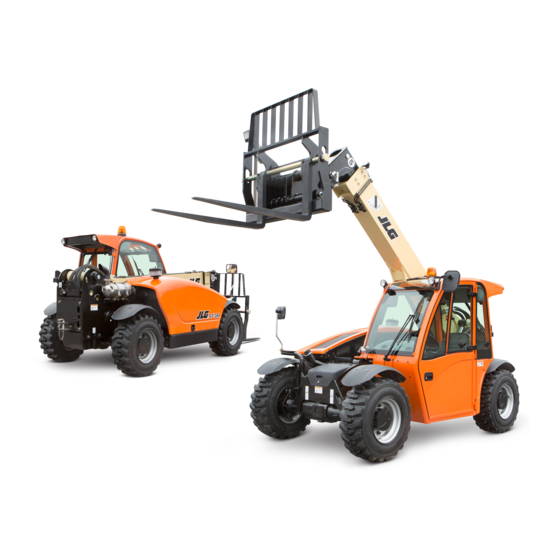
User Manuals: JLG G5-18A Compact Telehandler
Manuals and User Guides for JLG G5-18A Compact Telehandler. We have
2
JLG G5-18A Compact Telehandler manuals available for free PDF download: Service Manual, Operation Manual
JLG G5-18A Service Manual (192 pages)
Brand:
JLG
| Category:
Lifting Systems
| Size: 16 MB
Table of Contents
Section
5
Table of Contents
5
Subject
6
Safety Practices
10
Introduction
10
Disclaimer
10
Operation & Safety Manual
10
Do Not Operate Tags
10
Safety Information
10
Safety Alert System and Signal Words
10
Safety Instructions
11
Equipment Hazards
11
General Hazards
11
Operational Hazards
11
Personal Hazards
11
Safety Decals
12
Section 2 General Information and Specifications
13
General Information and Specifications
13
Replacement Parts and Warranty Information
14
Specifications
15
Travel Speed
15
Electrical System
15
Hydraulic Cylinder Performance Specifications
15
Engine Performance Specifications
16
Tires
16
Fluids, Lubricants and Capacities
17
Maintenance Schedules
18
10,1St 50 & 50 Hour Maintenance Schedule
18
1St 250, 250, 500 & 1000 Hour Maintenance Schedule
18
Lubrication Schedule
19
Hour Lubrication Schedule
19
Thread Locking Compound
20
Torque Charts
21
SAE Fastener Torque Chart
21
Metric Fastener Torque Chart
27
Hydraulic Connection Assembly and Torque Specification
32
Definitions
32
Assembly Instructions for American Standard Pipe Thread Tapered Connections
36
Assembly Instructions for British Standard Pipe Thread Tapered Connections
37
Assembly Instructions for 37° (JIC) Flare Fittings
38
Assembly Instructions for 45° SAE Flare Fittings
40
Assembly Instructions for O-Ring Face Seal (ORFS) Fittings
42
Assembly Instructions for DIN 24° Flare Bite Type Fittings (MBTL and MBTS)
44
Assembly Instructions for Bulkhead (BH) Fittings
46
Assembly Instructions for O-Ring Boss (ORB) Fittings
50
Assembly Instructions for Adjustable Port End Metric Fittings
58
Assembly Instructions for Metric ISO 6149 Port Assembly Stud Ends
66
Assembly Instructions for Adjustable Port End (BSPP) Fittings
68
Assembly Instructions for Flange Connections (FL61 and FL62)
76
Double Wrench Method
79
Adjustable Stud End Assembly
80
FFWR and TFFT Methods
80
O-Ring Installation (Replacement)
80
Section 3 Boom
81
Boom System Component Terminology
82
Boom System - Two Section Boom
83
Boom Assembly Maintenance
83
Boom System Description
83
Second Section Boom Removal
83
First Boom Section Removal
84
Complete Boom Removal
85
First Boom Section Installation
85
Second Boom Section Installation
85
Second Section Boom Removal
86
Boom Installation
87
Second Section Boom Installation
87
Tilt and Auxiliary Hose Removal
88
Tilt and Auxiliary Hose Installation
89
Extend/Retract Cylinder Installation
90
Extend/Retract Cylinder Removal
90
Boom Wear Pads
91
Wear Pad Inspection
91
Boom Wear Pad Replacement
91
Boom Wear Pad Lubrication
92
Quick Attach Assembly
93
Connecting with a Mechanical JLG Quick Attach
93
Connecting with a Hydraulic JLG Quick Attach
93
Connecting a Hydraulic Operated Attachment
94
Connecting with a Universal Quick Attach
94
Quick Attach Removal
94
Forks
95
Quick Attach Installation
95
Troubleshooting
96
Section 4 Cab and Covers
99
Cab and Covers
99
Operator's Cab and Covers Component Terminology
100
Cab Components
101
Operator's Cab Description
101
Serial Number Decal
101
Steering Wheel
101
Brake Pedal and Valve
102
Steering Column/Valve Replacement
102
Throttle Pedal Replacement
103
Heater/Defroster System
105
Joystick Assembly Replacement
105
Windshield Washer Assembly
105
Windshield Wiper Assembly
105
Operator's Cab
101
Cab Removal
106
Cab Installation
107
Section 5 Axles, Drive Shafts, Wheels and Tires
109
Axles, Drive Shafts, Wheels and Tires
110
Axle, Drive Shaft and Wheel Component Terminology
110
Axle Assemblies
111
Axle Serial Number Plate
111
Axle Internal Service
111
Axle Maintenance
111
Axle Specifications
111
Axle Removal
112
Axle Installation
113
Axle Assembly and Drive Shaft Troubleshooting
114
Steering System Purge Procedure
117
Drive Shafts
118
Drive Shaft Cleaning and Drying
118
Drive Shaft Inspection
118
Drive Shaft Installation
118
Drive Shaft Maintenance
118
Drive Shaft Removal
118
General Information
111
Wheels and Tires
119
Removing Wheel and Tire Assembly from Machine
119
Brakes
120
Installing Wheel and Tire Assembly Onto Machine
120
Brake Disk Inspection
120
Steering Angle Adjustment
120
Steering Adjustment
120
Section 6 Transmission
121
Transmission Assembly Component Terminology
122
Transmission Replacement
123
Transmission Maintenance
123
Transmission Removal
123
After Transmission Replacement
124
Transmission Disassembly
124
Transmission Installation
124
Transmission Specifications
123
Transmission Description
123
Transmission Filter Replacement
125
Filter Removal
125
Filter Installation
125
Towing a Disabled Machine
126
Section 7 Engine: Perkins 1104D-44T
127
Engine: Perkins 1104D-44T
127
Introduction
128
Disclaimer and Scope
128
Component Terminology
128
Engine Serial Number
130
Specifications and Maintenance Information
130
Engine Cooling System
130
Radiator Pressure Cap
130
Radiator/Oil Cooler and Coolant Heater Replacement
130
Engine Electrical System
131
Fuel System
131
Diesel Fuel
131
After Fuel System Service
132
Fuel/Hydraulic Oil Tank
132
Engine Exhaust and Air Cleaner System
133
Engine Replacement
133
Engine Removal
133
Engine Installation
134
Engine Coupler
135
Coupler Removal
135
Coupler Installation
135
Troubleshooting
136
Section 8 Hydraulic System
137
Hydraulic System
137
Hydraulic Component Terminology
139
Hoses, Tube Lines, Fittings, Etc
140
Replacement Considerations
140
Safety Information
140
Specifications
140
Hydraulic Pressure Diagnosis
141
Pressure Checks and Adjustments
141
Boom Function Pressure Checking
142
Charge Pressure Checking
142
Main Control Valve Pressure Checking
142
Steering Pressure Checking
143
Hydraulic Schematics
144
G5-18A
144
Auxiliary Options
146
Hydraulic System Pump
147
Pressurized Hydraulic Oil Fill Cap
147
Hydraulic Oil Reservoir Draining
147
Hydraulic Oil Reservoir Filling
147
Implement Pump Failure Analysis
147
Implement Pump Replacement
147
Hydraulic Reservoir
147
Front Drive Motor
149
Valves and Manifolds
150
Main Control Valve
150
Service Brake Valve
151
Parking Brake Valve
152
Brake Test
153
Pilot Select Valve
153
Steering Orbitrol Valve
153
Steer Select Valve
155
Joystick Enable Valve (CE)
157
Decompression Valve
158
Load Stability Indicator Valve (CE)
159
Hydraulic Cylinders
160
Section 9 Electrical System
165
Electrical Component Terminology
166
Electrical System
166
Specifications
167
Fuses and Relays
167
Electrical System Schematics
170
Cab Harness Schematic "A
170
Cab Harness Schematic "B
171
Cab Roof Schematic
172
Chassis Schematic
173
Options Chassis Schematic
174
Circuit Breakdowns
175
Charge Circuit Breakdown
175
Start Circuit Breakdown
176
Constant Power Circuit Breakdown
177
Drive Circuit Breakdown
178
Engine Start Circuit
179
Starter
179
Charging Circuit
180
Alternator
180
Electrical System Components
181
Back-Up Alarm
181
Instrument Cluster
181
Window Wiper/Washer
183
Windshield Wiper Motor
183
Rear Window or Roof Wiper Motor (if Equipped)
183
Cab Heater and Fan
184
Windshield Washer Reservoir and Pump
184
Cab Heater Controls
184
Switches, Solenoids and Senders
185
Ignition Key Switch
185
Dash Switches
186
Fuel Level Indicator and Fuel Level Sender
186
Hourmeter
186
Coolant Temperature Sender
187
Fuel Shut-Off Solenoid
187
Oil Pressure Sender
188
Advertisement
JLG G5-18A Operation Manual (160 pages)
Brand:
JLG
| Category:
Lifting Systems
| Size: 12 MB
Table of Contents
Read this First
4
Operator Qualifications
4
Modifications
4
Other Publications Available
6
Machine Configuration
6
Table of Contents
7
Table of Contents
13
Section 1 - General Safety Practices
13
Hazard Classification System
13
Safety Alert System and Safety Signal Words
13
General Precautions
13
Operation Safety
14
Electrical Hazards
14
Tip over Hazard
16
Travel Hazard
19
Load Falling Hazard
20
Lifting Personnel
21
Driving Hazards on Slopes
22
Pinch Points and Crush Hazards
23
Fall Hazard
25
Chemical Hazards
26
Clearsky (if Equipped)
27
Federal Communications Commission (FCC) Information for Users
27
Section 2 - Pre-Operation and Inspection
29
Pre-Operation Check and Inspection
29
Safety Decals
32
ANSI (G5-18A, if Equipped)
32
ISO (2505H) (G5-18A, if Equipped)
35
Walk-Around Inspection
38
Warm-Up and Operational Checks
40
Warm-Up Check
40
Operational Check
40
Operator Cab
41
Windows
42
Cab Door Window (if Equipped)
42
Rear Window
43
Table of Contents
45
Section 3 - Controls and Indicators
45
General
45
Controls
46
Park Brake
48
Parking Procedure
49
Ignition
50
Transmission Control Lever
51
Load Stability Indicator - LSI (2505H)
52
LSI Override Switch (2505H)
54
Steering Column Adjuster (if Equipped)
55
Instrument Panel
56
Joystick
58
Right Hand Console
60
Accessory Control Lever (if Equipped)
62
Reversing Fan (if Equipped)
63
Steer Modes
64
Steer Mode Change
64
Operator Seat
65
Operator Presence (CE & AUS)
65
Adjustments
66
Seat Belt
67
Boom Angle and Extension Indicators
68
Reverse Sensing System
69
Section 4 - Operation
71
Engine
71
Starting the Engine
71
Cold Weather Starting
72
Battery Boosted Starting
73
Normal Engine Operation
74
Shut-Down Procedure
74
Operating with a Non-Suspended Load
75
Lift Load Safely
75
Before Picking up a Load
75
Transporting a Load
76
Leveling Procedure
76
Placing a Load
77
Disengaging a Load
77
Operating with a Suspended Load (ANSI & CE)
78
Lift Load Safely
78
Picking up a Suspended Load
78
Transporting a Suspended Load
79
Leveling Procedure
79
Placing a Suspended Load
80
Disengaging a Suspended Load
80
Road Operation (2505H)
81
Loading and Securing for Transport
82
Tiedown
82
Lifting
83
Section 5 - Attachments and Hitches
85
Approved Attachments
85
Unapproved Attachments
85
JLG Supplied Attachments
86
Telehandler/Attachment/Fork Capacity
88
Use of the Capacity Chart
89
Capacity Indicator Locations
89
Sample Capacity Chart (ANSI & CE)
90
Sample Capacity Chart (AUS)
91
Example
92
Attachment Installation
93
Standard Quick Attach
93
Universal Quick Attach (UQC)
96
Hydraulic Operated Attachment
98
Adjusting/Moving Forks
99
Attachment Operation
100
Carriage with Forks
102
Fork Mounted Hook (ANSI & CE)
103
Side Tilt Carriage
104
Side Shift Carriage
106
Bucket
108
Grapple Bucket
110
Coupler Mounted Hook
112
5.10 Hitches
113
Retrieval Hitch
113
Adjustable Auto Hitch
114
Pin Hitch - CUNA C
115
EEC Manual Pin Hitch
116
Table of Contents
117
Section 6 - Emergency Procedures
117
Towing a Disabled Product
117
Moving Short Distances
117
Moving Longer Distances
117
Emergency Lowering of Boom
118
Emergency Exit from Enclosed Cab
119
Inside Cab
119
Outside Cab (if Equipped)
119
Section 7 - Lubrication and Maintenance
121
Introduction
121
Clothing and Safety Gear
121
General Maintenance Instructions
122
Service and Maintenance Schedule
123
10 & 1St 50 & 50 Hour Maintenance Schedule
123
1St 250, 250 & 500 Hour Maintenance Schedule
124
1000 & 1500 Hour Maintenance Schedule
125
Lubrication Schedules
126
250 Hour Lubrication Schedule
126
Operator Maintenance Instructions
128
Fuel System
128
Engine Oil
130
Hydraulic Oil
131
Tires
132
Air Intake System
134
Engine Cooling System
136
Battery
137
Brake System
138
Windshield Washer System (if Equipped)
139
Section 8 - Additional Checks
141
General
141
Load Stability Indicator System (2505H)
141
Reverse Sensing System (if Equipped)
142
Section 9 - Specifications
143
Product Specifications
143
Fluids
143
Capacities
146
Tires
147
Performance
148
Dimensions
149
Declaration of Vibration (CE)
150
Noise Emission Level (CE)
150
Machine Towing Capacity
150
Index
151
Inspection, Maintenance and Repair Log
155
Advertisement
Related Products
JLG G6-42A
JLG G9-43A
JLG G10-43A
JLG G6-42P
JLG G10-55A
JLG G12-55A
JLG GRADALL 534D-6
JLG GRADALL 534D-6T
JLG GRADALL 522
JLG GRADALL 524
JLG Categories
Boom Lifts
Lifting Systems
Scissor Lifts
Construction Equipment
Work Light
More JLG Manuals
Login
Sign In
OR
Sign in with Facebook
Sign in with Google
Upload manual
Upload from disk
Upload from URL