Sign In
Upload
Manuals
Brands
Intel Manuals
Chassis
SC5275-E UP
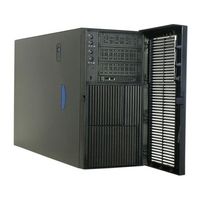
Intel SC5275-E UP Manuals
Manuals and User Guides for Intel SC5275-E UP. We have
4
Intel SC5275-E UP manuals available for free PDF download: User Manual, Technical Product Specification, Install Manual, Configuration Manual
Intel SC5275-E UP User Manual (73 pages)
Entry Server Chassis
Brand:
Intel
| Category:
Chassis
| Size: 2 MB
Table of Contents
About this Manual
3
Manual Organization
3
Product Accessories
3
Additional Information and Software
4
Safety Information
5
Warnings
5
Safety Cautions
6
Wichtige Sicherheitshinweise
7
Instrucciones de Seguridad Importantes
11
Table of Contents
15
Tables
19
Figures
19
Chassis Description
19
Kit Contents
19
Feature Summary
19
Figure 1. Screw Description
19
Table 1. Feature Summary
19
Chassis Front View
20
Front Panel Controls and Indicators
21
Table 2. LED Description
21
Chassis Rear View
22
Peripherals
23
5.25-Inch Removable Media Drive Bays
23
3.5-Inch Hard Drive Bays
23
Optional 3.5-Inch Hot Swap Drive Bay
23
Accessories and Order Codes
23
Table 3. Accessories and Order Codes
23
Power Supply
24
Checking the Power Cord
24
Chassis Security
24
Monitoring
24
Mechanical Locks
25
Figure 2. Mechanical Locks
25
Setting up the Chassis
27
Tools and Supplies Needed
27
Installation Safety Instructions
27
Safety: before You Remove the Access Covers
27
Warnings and Cautions
28
Remove the Access Cover
29
Figure 3. Removing the Access Cover
29
Remove the Front Bezel
30
Figure 4. Removing the Front Bezel
30
Install the I/O Shield
31
Figure 5. Installing the I/O Shield
31
Install the Server Board Standoffs and Bumpers
32
Install a 3.5-Inch Floppy Drive
32
Peripheral Drives
33
Device Installation Considerations
33
IDE Requirements
34
Installing a 5.25-Inch Removable Media Device
34
Install the Server Board
37
Installing 3.5-Inch Hard Drive
38
Connect Cables to the Server Board
41
Installing an Add-In Board
42
Install the Front Bezel
44
Install the Access Cover
45
Maintaining Your Server
47
Tools and Supplies Needed
47
Safety: before You Remove the Access Cover(S)
47
Warnings and Cautions
47
Replacing Fans
49
Replacing a Front System Fan
49
Replacing a Rear System Fan
50
Replacing the Power Supply
51
Replacing the Front Panel Board
52
Replacing the USB Cable
54
Technical Reference
57
Power Supply Specifications
57
600 Watt Single Power Supply Input Voltages
57
600 Watt Single Power Supply Output Voltages
57
Table 4. Power Supply System Output Capability
57
System Environmental Specifications
58
Table 5. Environmental Specifications
58
Equipment Log and Worksheets
59
Equipment Log
59
Current Usage
61
Calculating Power Usage
61
Table 6. Power Usage Worksheet 1
61
Table 7. Power Usage Worksheet 2
61
Regulatory and Compliance Information
63
Product Regulatory Compliance
63
Product Safety Compliance
63
Product EMC Compliance - Class a Compliance
63
Certifications / Registrations / Declarations
64
Product Regulatory Compliance Markings
64
Table 8. Product Certification Markings
64
Electromagnetic Compatibility Notices
65
Fcc (Usa)
65
Industry Canada (ICES-003)
66
Europe (CE Declaration of Conformity)
66
VCCI (Japan)
67
BSMI (Taiwan)
67
Korean RRL Compliance
67
Regulated Specified Components
68
Getting Help
69
World Wide Web
69
Warranty
71
Limited Warranty for Intel Chassis Subassembly Products
71
Extent of Limited Warranty
71
Warranty Limitations and Exclusions
72
Limitations of Liability
72
How to Obtain Warranty Service
73
Telephone Support
73
Returning a Defective Product
73
Advertisement
Intel SC5275-E UP Technical Product Specification (43 pages)
Server Chassis
Brand:
Intel
| Category:
Chassis
| Size: 1 MB
Table of Contents
Table of Contents
3
1 Introduction
9
2 Chassis
10
System Color
10
Front Bezel Features
10
Security
10
Table 1. Chassis Dimensions (Approximate)
10
I/O Panel
11
Chassis Views
11
Figure 1. ATX 2.2 I/O Aperture
11
Figure 2. Front Closed View of the Intel® Server Chassis SC5275-E
11
Figure 3. Rear Closed View of the Intel® Server Chassis SC5275-E
12
Figure 4. Front Internal View of the Intel® Server Chassis SC5275-E
13
Figure 5. Rear Internal View of the Intel® Server Chassis SC5275-E
13
3 Chassis Power Subsystem
14
600W Power Supply
14
Mechanical Outline
14
Figure 6. Mechanical Outline of Power Suppy
14
Output Wire Harness
15
Table 2: Cable Lengths
15
Table 3. Pin-Out Baseboard Power Connector P1
15
Table 4. Processor Power Connector P2
16
Table 5: Power Signal Connector
17
Table 6: PCI Express Connector
17
Table 7: Peripheral Power Connectors
17
Table8: Peripheral Power Connectors
17
AC Input Requirements
18
AC Inlet Connector
18
Table 9. Floppy Power Connector P6
18
Table 10: SATA Power Connector
18
Table 11: SATA Power Connector
18
600W DC Output Specifications
19
Table 12: Voltage Regulation Limits
19
Protection Circuits
20
Current Limit (OCP)
20
Over Voltage Protection (OVP)
20
Over Temperature Protection (OTP)
20
Control and Indicator Functions
20
PSON# Input Signal
20
PWOK (Power OK) Output Signal
20
Mean Time between Failures (MTBF)
20
Smbus Monitoring Interface
21
4 System Cooling
21
Fan Configuration
21
Fan Control
21
Cooling Solution
21
Figure 72:Cooling Fan Configuration
22
Workstation Cooling Kit Solution
23
5 System Peripheral Bays
24
In Peripheral Drive Bay
24
In Peripheral Drive Bays
24
Figure 8: Drive Bay Locations for Server Chassis SC5275-E
24
6 Hard Disk Drive Bays
25
Fixed Hard Drive Bay
25
SCSI Interface
25
SCSI Hot Swap Backplane Specifications
25
FET Short Protection
26
Device SCSI ID
26
Hard Drive Activity LED
26
Table 13. SCSI ID Assignments
26
Table 14. Hard Drive Activity LED
26
Hard Drive Fault LED
27
Hot Swap Drive Bay Electronics
27
Figure 9: 6-HDD Hot Swap Drive Bay, Front/Rear Isometric View
27
Figure 10: Drive Carrier with Air Baffle Installed
27
SATA Hardware Overview
28
SATA Hot Swap Drive Cage Upgrade Kit
28
Connect SATA Backplane Cables
28
Front Panel
28
Table 15. SATA Drive Connectors
28
Figure 11: Front Panel Controls and Indicators
29
Table 16. Front Panel LED Functions
29
7 System Interconnection
30
Signal Definitions
30
Chassis Internal Cables
30
Front Panel Cable
30
USB Cable
30
Fan Connector
30
Server Board Internal Cables
30
Accessory Cables
31
ICMB Interface Card Cable
31
External SCSI Cable
31
I/O Panel Connectors
31
8 Compatible Intel Server Boards
32
9 Product Regulatory Compliance
32
Product Safety Compliance
32
Product EMC Compliance
32
Product Regulatory Compliance Markings
32
Electromagnetic Compatibility Notices
33
Usa
33
FCC Verification Statement
34
ICES-003 (Canada)
34
Europe (CE Declaration of Conformity)
34
Japan EMC Compatibility
34
BSMI (Taiwan)
35
10 Environmental Limits
35
System Office Environment
35
System Environmental Testing
35
Table 17. System Office Environment Summary
35
11 Reliability, Serviceability, and Availability
36
Mtbf
36
Serviceability
36
Table 18. MTBF Calculations
36
Table 19. Maximum Maintenance Procedure Times
36
12 Upgradeability
37
SCSI Hot Swap Drive Bay Upgrade
37
External SCSI Adapter Cable
37
Figure 12: Replacing System Fan from IDE Drive Carrier to the SCSI Drive Carrier
37
SATA Hot Swap Drive Bay Upgrade
38
Figure 13. External SCSI Adapter Cable Detail
38
Figure 14: Replacing System Fan from IDE Drive Carrier to the SATA Drive Carrier
38
Appendix A: Chassis Spares and Accessories
39
Upgrade and Accessory Parts
39
Replacement and Spare Parts for Intel® Server Chassis SC5275-E
39
Glossary
41
Reference Documents
43
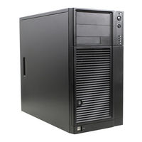
Intel SC5275-E UP Install Manual (34 pages)
Local Control Panel Kit for Entry Server Chassis
Brand:
Intel
| Category:
Chassis
| Size: 1 MB
Table of Contents
Safety Information
3
Important Safety Instructions
3
Wichtige Sicherheitshinweise
3
Consignes de Sécurité
3
Instrucciones de Seguridad Importantes
3
Table of Contents
5
Local Control Panel Kit Installation Instructions
9
Before You Begin
9
Kit Content List
9
Tools and Supplies Needed
10
System References
10
Installation Instructions for Intel® Server Chassis SC5300/SC5400
10
Remove Access Cover
10
Figure 1. Removing Access Cover
10
Remove Bezel Assembly
11
Figure 2. Removing Bezel Assembly
11
Remove Outer Bezel Door from Bezel Assembly
12
Figure 3. Removing Outer Bezel Door from Bezel Assembly
12
Remove Upper Third of Bezel Grill
13
Install LCP Grill
13
Figure 4. Removing Upper One-Third of Bezel Grill
13
Figure 5. Installing LCP Grill
13
Remove Lowest CD-ROM/DVD Drive Filler Panel
14
Figure 6. Removing Lowest Floppy/CD-ROM/DVD Drives or Filler Panel
14
Install EMI Shield Onto LCP Carrier
15
Inserting LCP Carrier into Drive Bay of Server Chassis
15
Figure 7. Installing EMI Shield on LCP Carrier
15
Figure 8. Attaching Drive Rails to LCP Carrier
15
Route LCP Cable
16
Figure 9. Installing LCP Carrier
16
Figure 10. Routing the LCP Cable
16
Connect LCP Cable to LCP Header of Server Board
17
Figure 11. Attaching LCP Cable to Header on Intel® Server Board SE7520AF2
17
Replace Bezel Assembly
18
Figure 12. Attaching LCP Cable to Header on Intel® Server Board SE7520BD2
18
Replace Access Cover
19
Figure 13. Installing Inner Bezel Door
19
Figure 14. Replacing Access Cover
19
Installation Instructions for Intel® Entry Server Chassis SC5275-E
20
Remove Access Cover
20
Figure 15. Removing Access Cover
20
Remove Bezel
21
Remove Lowest CD-ROM/DVD Drive Filler Panel
21
Figure 16. Removing Bezel
21
Figure 17. Removing Lowest Floppy/CD-ROM/DVD Drives or Filler Panel
21
Install EMI Shield Onto LCP Carrier
22
Inserting LCP Carrier into Drive Bay of Server Chassis
22
Figure 18. Installing EMI Shield on LCP Carrier
22
Figure 19. Installing Drive Rails to LCP Carrier
22
Figure 20. Inserting LCP Carrier into Drive Bay
23
Figure 21. Routing LCP Cable in Intel® Entry Server Chassis SC5275-E
23
Connect LCP Cable to LCP Header on Server Board
24
Figure 22. Attaching LCP Cable to Header on Intel® Server Board SE7520AF2
24
Replace Bezel
25
Figure 23. Attaching LCP Cable to Header on Intel® Server Board SE7520BD2
25
Replace Access Cover
26
Figure 24. Installing Bezel
26
Figure 25. Replacing Access Cover
26
Installation Instructions for Intel® Entry Server Chassis SC5299-E
27
Remove Access Cover
27
Remove Bezel
27
Figure 26. Removing Access Cover
27
Remove Lowest CD-ROM/DVD Drive Filler Panel
28
Figure 27. Removing Bezel
28
Figure 28. Removing Lowest Floppy/CD-ROM/DVD Drives or Filler Panel
28
Install EMI Shield Onto LCP Carrier
29
Figure 29. Installing EMI Shield on LCP Carrier
29
Inserting LCP Carrier into Drive Bay of Server Chassis
30
Route LCP Cable
30
Figure 30. Inserting LCP Carrier into Drive Bay
30
Figure 31. Routing LCP Cable
30
Connect LCP Cable to LCP Header on Server Board
31
Figure 32. Attaching LCP Cable to Header on Intel® Server Board S5000VSA
31
Figure 33. Attaching LCP Cable to Header on Intel® Server Board S5000PSL or Intel® Server Board XVN
31
Figure 34. Installing Bezel
32
Figure 35. Replacing Access Cover
33
Advertisement
Intel SC5275-E UP Configuration Manual (7 pages)
Spares / Parts List & Configuration Guide
Brand:
Intel
| Category:
Computer Hardware
| Size: 0 MB
Table of Contents
Table of Contents
2
Contents
2
Change History
2
Disclaimer
2
Production Configurations
3
Production Board and Kdks
3
A1. DDR2 400 Board Skus - Production
4
A2. Spare – Production
4
Production Order Codes
4
A3. Chassis – Production
5
Chassis - Production Codes
5
A4. Chassis Spares & Accessories – Production
6
Chassis Spares & Accessories - Production Codes
6
Chassis Spares & Accessories - Production Codes, Continued
7
Advertisement
Related Products
Intel SC5275-E DP
Intel SC5275-E WS
Intel SC5275-E BRP
Intel SC5299DPNA
Intel SC5299WS
Intel SC5299UP - Server Chassis Tower
Intel SC5295-E
Intel SC5299-E BRP
Intel SC5299-E UP
Intel SC5299-E Series
Intel Categories
Motherboard
Computer Hardware
Server
Desktop
Server Board
More Intel Manuals
Login
Sign In
OR
Sign in with Facebook
Sign in with Google
Upload manual
Upload from disk
Upload from URL