Sign In
Upload
Manuals
Brands
IEI Technology Manuals
Touch Panel
afl2-w15b-h61
IEI Technology afl2-w15b-h61 Manuals
Manuals and User Guides for IEI Technology afl2-w15b-h61. We have
1
IEI Technology afl2-w15b-h61 manual available for free PDF download: Introductory Manual
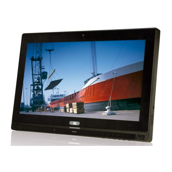
IEI Technology afl2-w15b-h61 Introductory Manual (218 pages)
flat bezel panel pc with 2nd generation Intel Core i7/i5/i3, pentium and Celeron Processor, Touchscreen, Wi-Fi, USB, GbE LAN, RS-232/422/485, 1.3M Pixels Camera, HD Audio and RoHS
Brand:
IEI Technology
| Category:
Touch Panel
| Size: 12 MB
Table of Contents
Table of Contents
4
List of Figures
10
List of Tables
15
Introduction
18
1.1 Overview
19
Figure 1-1: AFL2-W15B-H61 Flat Bezel Panel PC
19
1.1.1 Model Variations
20
Table 1-1: AFL2-W15B-H61 Model Variations
20
1.1.2 Features
21
1.1.3 Light Fanless Technology Design
21
1.2 External Overview
21
1.2.1 Front Panel
21
1.2.1.1 LED Indicators
22
Figure 1-2: Front View
22
Figure 1-3: LED Indicators
22
1.2.1.2 Function Keys
24
Figure 1-4: Function Keys
24
Table 1-2: LED Indicators
24
1.2.2 Rear Panel
25
Table 1-3: Function Key Descriptions
25
1.2.3 Bottom Panel
26
Figure 1-5: Rear View
26
1.2.4 Side Panels
27
Figure 1-6: Bottom Panel
27
1.3 Dimensions
28
Figure 1-7: Side Panels
28
1.4 Internal Overview
29
F Igure 1-8: AFL2-W15B-H61 Dimensions
29
1.5 System Specifications
30
Table 1-4: System Specifications
31
Unpacking
32
2.1.1 Packing List
33
Installation
37
Anti - Static Precautions
38
3.2 Installation Precautions
38
3.3 Installation and Configuration Steps
39
3.4 HDD Installation
39
Figure 3-1: HDD Cover Retention Screws
40
Figure 3-2: HDD Bracket Removal
40
Figure 3-3: Inserting the HDD
41
Figure 3-4: Securing the HDD
41
3.5 CF Card Installation
42
Figure 3-5: CF Card Location
42
Figure 3-6: Insert CF Card
42
RFID Reader Installation (Optional)
43
Figure 3-7: Back Cover Retention Screws
43
Figure 3-8: Internal Cover Retention Screws
43
Figure 3-9: RFID Reader Module Installation
44
Figure 3-10: RFID Reader Connection
44
3.7 AT/ATX Mode Selection
45
3.7.1 at Power Mode
45
3.7.2 ATX Power Mode
45
Figure 3-11: AT/ATX Switch Location
45
3.8 Clear CMOS
46
Figure 3-12: Clear CMOS Switch Location
46
Figure 3-13: Reset Button Location
46
Mounting the System
47
Powering off the System
47
Powering on the System
47
Figure 3-14: Wall-Mounting Bracket
48
Figure 3-15: Chassis Support Screws
50
F Igure 3-16: Secure the Panel
50
Figure 3-17: Cutout Dimensions
51
Panel Mounting
51
Cabinet and Rack Installation
52
Figure 3-18: Tighten the Panel Mounting Clamp Screws
52
Figure 3-19: the Rack/Cabinet Bracket
53
Figure 3-20: Secure the Rack/Cabinet Bracket
54
Figure 3-21: Install into a Rack/Cabinet
54
Arm Mounting
55
Figure 3-22: Arm Mounting Retention Screw Holes
56
F Igure 3-23: Arm Mounting (ARM-11
56
Figure 3-24: Stand Mounting (Stand-A/Bxx)
57
Audio Connection
58
Figure 3-25: Audio Connector
59
Hdmi Device Connection
59
Figure 3-26: HDMI Connection
60
Lan Connection
60
Db-9 Serial Port Connection
61
Figure 3-27: LAN Connection
61
Serial Device Connection
61
Figure 3-28: DB-9 Serial Port Connector
62
Rj-45 Serial Port Connection
62
Figure 3-29: RJ-45 Serial Port Connector
63
Figure 3-30: Type K Temperature Sensor Installation
63
Figure 3-31: USB Device Connection
64
Vga Monitor Connection
65
Bios Setup
66
Starting Setup
67
Using Setup
67
Table 6-1: BIOS Navigation Keys
68
Getting Help
68
Unable to Reboot after Configuration Changes
68
Bios Menu Bar
68
BIOS Menu 1: Main
69
Acpi Settings
71
BIOS Menu 2: Advanced
71
BIOS Menu 3: ACPI Configuration
72
Rtc Wake Settings
72
BIOS Menu 4: RTC Wake Settings
73
BIOS Menu 5: TPM Configuration
74
Cpu Configuration
74
Trusted Computing
74
BIOS Menu 6: CPU Configuration
75
Cpu Information
75
BIOS Menu 7: CPU Configuration
76
BIOS Menu 8: IDE Configuration
77
Sata Configuration
77
BIOS Menu 9: Intel TXT(LT) Configuration
78
BIOS Menu 10: USB Configuration
79
BIOS Menu 11: Super IO Configuration
80
F81216 Super Io Configuration
80
BIOS Menu 12: Serial Port N Configuration Menu
81
BIOS Menu 13: Hardware Health Configuration
84
BIOS Menu 14: Serial Port Console Redirection
87
BIOS Menu 15: Iei Feature
88
BIOS Menu 16: Chipset
89
BIOS Menu 17: Northbridge Chipset Configuration
90
BIOS Menu 18: Southbridge Chipset Configuration
91
BIOS Menu 19: Integrated Graphics
95
BIOS Menu 20: ME Subsystem
96
BIOS Menu 21: Boot
97
BIOS Menu 22: Security
99
BIOS Menu 23: Exit
100
Software Drivers
102
Available Software Drivers
103
Figure 5-1: Drivers
104
Chipset Driver Installation
104
Figure 5-2: Chipset Driver Screen
105
Figure 5-3: Chipset Driver Welcome Screen
105
Figure 5-4: Chipset Driver License Agreement
106
Figure 5-5: Chipset Driver Read Me File
107
Figure 5-6: Chipset Driver Setup Operations
107
Figure 5-7: Chipset Driver Installation Finish Screen
108
Graphics Driver Installation
108
Figure 5-8: Graphics Driver Read Me File
109
Figure 5-9: Graphics Driver Setup Files Extracted
109
Figure 5-10: Graphics Driver Welcome Screen
110
Figure 5-11: Graphics Driver License Agreement
110
Figure 5-12: Graphics Driver Read Me File
111
Figure 5-13: Graphics Driver Setup Operations
111
Figure 5-14: Graphics Driver Installation Finish Screen
112
Lan Driver Installation
112
Figure 5-15: LAN Driver Welcome Screen
113
Figure 5-16: LAN Driver Ready to Install Screen
113
Figure 5-17: LAN Driver Setup Status Screen
114
Figure 5-18: LAN Driver Installation Complete
114
Audio Driver Installation
114
Figure 5-19: Audio Driver Welcome Screen
115
Figure 5-20: Audio Driver Installation
116
Figure 5-21: Audio Driver Installation Complete
116
Figure 5-22: Touch Screen Driver Welcome Screen
117
Figure 5-23: Touch Screen Driver License Agreement
118
Figure 5-24: Touch Screen Driver Choose Install Location
118
Figure 5-25: Touch Screen Driver Installation Screen
119
Figure 5-26: Touch Screen Driver Update Complete
119
Figure 5-27: Penmount Monitor Icon
120
Figure 5-28: Penmount Monitor Popup Menu
120
Figure 5-29: Configuration Screen
121
Figure 5-30: Calibration Initiation Screen
121
Figure 5-31: Calibration Screen
122
Figure 5-32: License Agreement
122
Figure 5-33: Setup Type
123
Figure 5-34: Configuration Tool
124
Figure 5-35: Ready to Install the Program
124
Figure 5-36: Setup Status
125
Figure 5-37: Installation Complete
125
Figure 5-38: USB 3.0 Driver Welcome Screen
126
Figure 5-39: USB 3.0 Driver License Agreement
127
Figure 5-40: USB 3.0 Driver Installation
127
Figure 5-41: USB 3.0 Driver Update Complete
128
System Monitoring
129
Figure 6-1: Cooling Management Console Setup Wizard
130
Figure 6-2: Select Installation Folder
131
Figure 6-3: Confirm Installation
131
Figure 6-4: Installation Complete
132
Figure 6-5: Restart the System
132
Figure 6-6: Cooling Management Console Icon
133
Figure 6-7: ICMC
133
Information Panel
133
Figure 6-8: ICMC Information Panel
134
Table 6-1: ICMC Information Panel Description
135
Figure 6-9: ICMC - Chart Panel
136
Figure 6-10: ICMC - Time Interval Adjustment
137
System Maintenance
138
System Maintenance Introduction
139
Opening the System
140
Removing the Back Cover
140
Turn off the Power
140
Figure 7-1: Back Cover Retention Screws
141
Removing the Internal Aluminum Cover
141
Figure 7-2: Internal Cover Retention Screws
142
Figure 7-3: Internal Components
142
Replacing Components
142
Figure 7-4: DDR SO-DIMM Module Installation
143
Figure 7-5: Removing the Antennas
144
Wlan Card Replacement
144
Figure 7-6: Releasing the WLAN Card
145
Figure 7-7: Removing the WLAN Card
145
Figure 7-8: Attaching the Antennas
146
Reinstalling the Covers
146
Interface Connectors
147
Figure 8-1: Main Board Layout Diagram
148
Peripheral Interface Connectors
148
Internal Peripheral Connectors
149
Battery Connector (Bat)
150
Table 8-1: Peripheral Interface Connectors
150
Table 8-2: Auto-Dimming Connector (JP3) Pinouts
150
Table 8-3: Battery Connector (BAT2) Pinouts
150
Ec Debug Connector (Cn)
151
Fan Connector (Cpu_Fan)
151
Table 8-4: Bluetooth USB Connector (BLUETOOTH1) Pinouts
151
Table 8-5: EC Debug Connector (CN15) Pinouts
151
Table 8-6: Fan Connector (CPU_FAN1) Pinouts
151
Hdd Connector (Jsata)
152
Hot Key Connector (Hotkeycn)
152
Hot Key Led Connector (Hotkeyledcn)
152
Table 8-7: HDD Connector (JSTAT3) Pinouts
152
Table 8-8: Hotkey LED Connector (HOTKEYLEDCN1) Pinouts
152
Table 8-9: Hotkey Connector (HOTKEYCN1) Pinouts
152
Lvds Connector (Lvds)
153
Table 8-10: LED Indicator Connector (LEDCN1) Pinouts
153
Table 8-11: Logo LED Connector ( LOGO_LED ) Pinouts
153
Microphone Connector (DMIC)
154
Table 8-12: LVDS Connector (LVDS1) Pinouts
154
Table 8-13: LVDS Backlight Connector (INVERTER1) Pinouts
154
Table 8-14: Microphone Connector (DMIC1) Pinouts
154
Power Button Connector (Pw_Bt)
155
Table 8-15: Mini USB Connector (MINUSB1) Pinouts
155
Table 8-16: Mini USB Connector (MINUSB2) Pinouts
155
Sata Connector (Sata)
156
Table 8-18: RFID USB Connector (RFID_USB1) Pinouts
156
Table 8-19: SATA Connector (SATA1) Pinouts
156
Table 8-20: SATA Power Connector (CN8) Pinouts
156
Speaker Connector (Spk_Cn)
157
Table 8-21: Speaker Connector (SPK_CN13) Pinouts
157
Table 8-22: SPI Flash Connector (JSPI1) Pinouts
157
Table 8-23: EC SPI Flash Connector (JSPI2) Pinouts
157
Table 8-24: Touch Panel Connector (TS1) Pinouts
158
Table 8-25: TPM Connector (TPM1) Pinouts
158
Tpm Connector (Tpm)
158
External Interface Panel Connectors
159
Table 8-26: Type K Thermocouple Connector (CN13, CN14) Pinouts
159
Table 8-27: Webcam Connector (WEBCAMER1) Pinouts
159
F Igure 3-32: VGA Connector
160
Table 8-28: Rear Panel Connectors
160
Table 8-29: Audio MIC-In Jack (MIC1) Pinouts
160
Table 8-30: Audio Lline-Out Jack (LINE_OUT1) Pinouts
160
Table 8-31: Ethernet Connector (LAN2) Pinouts
160
Ethernet Connector (Lan)
160
Table 8-32: HDMI Connector (HDMI1) Pinouts
161
Table 8-33: Power Connector (PWR1) Pinouts
161
Hdmi Connector (Hdmi)
161
Power Connector (Pwr)
161
Table 8-34: RS-232 Serial Ports (COM1, COM2) Pinouts
161
Table 8-35: RS-422/485 Serial Port (COM3) Pinouts
162
Table 8-36: USB 2.0 Connectors (USB01) Pinouts
162
Table 8-37: USB 2.0 Connector (USB023) Pinouts
162
Table 8-39: VGA Connector (VGA1) Pinouts
163
Table 8-40: Jumpers
163
Table 8-41: LVDS Voltage Selection Jumper (DJ2) Settings
163
Lvds Panel Voltage Selection Jumper (Dj)
163
Vga Connector (Vga)
163
Table 8-42: LVDS Panel Jumper (DPANEL1) Settings
164
Safety Precautions
165
Bios Menu Options
170
Figure C-1: IEI One Key Recovery Tool Menu
174
Figure C-2: Launching the Recovery Tool
179
Figure C-3: Recovery Tool Setup Menu
179
Figure C-4: Command Prompt
180
Figure C-5: Partition Creation Commands
181
Figure C-6: Launching the Recovery Tool
183
Figure C-7: Manual Recovery Environment for Windows
183
Figure C-8: Building the Recovery Partition
184
Figure C-9: Press any Key to Continue
184
Figure C-10: Press F3 to Boot into Recovery Mode
185
Figure C-11: Recovery Tool Menu
185
Figure C-12: about Symantec Ghost Window
186
Figure C-13: Symantec Ghost Path
186
Figure C-14: Select a Local Source Drive
187
Figure C-15: Select a Source Partition from Basic Drive
187
F Igure C-16: File Name to Copy Image
188
Figure C-17: Compress Image
188
Figure C-18: Image Creation Confirmation
189
Figure C-19: Image Creation Complete
189
Figure C-20: Image Creation Complete
189
Figure C-21: Press any Key to Continue
190
Figure C-22: Auto Recovery Utility
191
Figure C-23: Disable Automatically Restart
191
Figure C-24: Launching the Recovery Tool
192
Figure C-25: Auto Recovery Environment for Windows
192
Figure C-26: Building the Auto Recovery Partition
193
Figure C-27: Factory Default Image Confirmation
193
Figure C-28: Image Creation Complete
194
Figure C-29: Press any Key to Continue
194
BIOS Menu 24: IEI Feature
195
Figure C-30: Partitions for Linux
196
Figure C-31: Manual Recovery Environment for Linux
197
Figure C-32: Access Menu.lst in Linux (Text Mode)
197
Figure C-33: Recovery Tool Menu
198
Figure C-34: Recovery Tool Main Menu
199
Figure C-35: Restore Factory Default
200
Figure C-36: Recovery Complete Window
200
Figure C-37: Backup System
201
Figure C-38: System Backup Complete Window
201
Figure C-39: Restore Backup
202
Figure C-40: Restore System Backup Complete Window
202
Figure C-41: Symantec Ghost Window
203
Figure C-42: Disable Automatically Restart
210
Advertisement
Advertisement
Related Products
IEI Technology AFL2-W15A-N270
IEI Technology AFL2-W15A-N270/R/2G-R20
IEI Technology AFL2-W15A-N270/R-EM/1G-R20
IEI Technology AFL2-W19AB-H61 Series
IEI Technology AFL2-W19A-H61-i5/R-R11
IEI Technology AFL2-W19AB-H61-i3/R-R11
IEI Technology AFL2-W19AB-H61-i3/PC-R11
IEI Technology AFL2-W19A-H61-P/R-R11
IEI Technology AFL2-W19A-H61-P/PC-R11
IEI Technology AFL2-W19AB-H61-P/PC-R11
IEI Technology Categories
Motherboard
Touch Panel
Computer Hardware
Single board computers
Desktop
More IEI Technology Manuals
Login
Sign In
OR
Sign in with Facebook
Sign in with Google
Upload manual
Upload from disk
Upload from URL