Sign In
Upload
Manuals
Brands
IEI Technology Manuals
Touch Panel
AFL2-W19A-H61-i5/R-R11
IEI Technology AFL2-W19A-H61-i5/R-R11 Manuals
Manuals and User Guides for IEI Technology AFL2-W19A-H61-i5/R-R11. We have
1
IEI Technology AFL2-W19A-H61-i5/R-R11 manual available for free PDF download: User Manual
IEI Technology AFL2-W19A-H61-i5/R-R11 User Manual (279 pages)
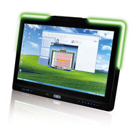
Flat Bezel Panel PC with 2nd Generation Intel Core i7/ i5/ i3, Pentium and Celeron processor, Touch Screen, Wi-Fi, USB, Dual GbE LAN , RS-232/422/485, 1.3M pixels Camera, HD Audio and RoHS
Brand:
IEI Technology
| Category:
Touch Panel
| Size: 11 MB
Table of Contents
Table of Contents
4
Introduction
21
Afl2-W19A/Ab-H61 Flat Bezel Panel Pc Overview
22
Figure 1-1: AFL2-W19A/AB-H61 Flat Bezel Panel PC
22
Model Variations
23
Features
23
Table 1-1: AFL2-W19A/AB-H61 Model Variations
23
Light Fanless Technology Design
24
External Overview
25
Front Panel
25
LED Indicators
25
Figure 1-2: AFL2-W19A/AB-H61 Front View
25
Figure 1-3: LED Indicators
25
Table 1-2: LED Indicators
26
LED Light
27
Figure 1-4: LED Light Software (Auto)
27
Figure 1-5: LED Light Software (Manual)
27
Function Keys
28
Figure 1-6: Function Keys
28
Table 1-3: Function Key Descriptions
28
Rear Panel
29
Bottom Panel
29
Figure 1-7: AFL2-W19A/AB-H61 Rear View
29
Left Side Panel
30
Figure 1-8: AFL2-W19A/AB-H61 Bottom Panel
30
Right Side Panel
31
Internal Overview
31
Figure 1-9: AFL2-W19A/AB-H61 Left Side Panel
31
Figure 1-10: AFL2-W19A/AB-H61 Right Side Panel
31
System Specifications
32
Table 1-4: System Specifications
33
Led Light Bar (Optional)
34
Overview
35
I E Iled Light Bar Display Simulator
35
Figure 2-1: the Setup Wizard Starts
35
Figure 2-2: Select Installation Folder Screen
36
Figure 2-3: Confirm Installation Screen
37
Figure 2-4: Installation Complete
38
Figure 2-5: Iei LED Light Bar Display Simulator
39
Figure 2-6: Color Setting Area
40
Figure 2-7: Color Palette
40
Table 2-1: LED Simulator Software Description
40
Figure 2-8: Simulate the LED Light
41
Figure 2-9: Set the Left Leds
42
Figure 2-10: Set All the Leds
42
Figure 2-11: Light Duration
43
Figure 2-12: Add New Command
44
Figure 2-13: Add Loop Start
44
I E Iled Run
45
Figure 2-14: Add Loop End
45
Figure 2-15: Iei LED RUN Software
45
Led Control Api
46
Introduction
46
Programming Language Support
46
Application Content
46
LED Control API Functions
46
Lightbar_Driverinit
46
Lightbar_Driveruninit
47
Lightbar_Deviceinit
47
Lightbar_Deviceclose
47
Lightbar_Brightness_Single
48
Lightbar_Blnk_Settings
48
Lightbar_Blnk_Type
49
Lightbar_Led_Modeset
49
Structures
50
Led_Color_Info
50
Led_Blnk_Set
50
Led_Blnk_Set
51
Led_Mode_Settings
52
Programming Example
52
Turn on LED - Single
52
Turn on LED - Multiple
53
LED Blink - 1
55
LED Blink - 2
56
Detailed Specifications
59
Dimensions
60
Figure 3-1: AFL2-W19A/AB-H61 Dimensions (MM)
60
Intel ® Core ™ Desktop Processor
61
Motherboard Components
61
Memory Capacity
61
Storage Capacity
61
External Peripheral Interface Connectors
61
Serial Port Connectors
61
LAN Connectivity
62
Figure 3-2: Serial Ports
62
Figure 3-3: RJ-45 Ethernet Connector (Bottom Panel)
62
External USB Connectors
63
Figure 3-4: RJ-45 Ethernet Connector (Left Side Panel)
63
Figure 3-5: External USB Ports (Bottom Panel)
63
Audio
64
Audio Codec Controller
64
Stereo Speakers
64
Figure 3-6: External USB Ports (Left Side Panel)
64
Figure 3-7: Audio Jack
64
Unpacking
65
Unpacking
66
Packing List
66
Installation
70
Anti - Static Precautions
71
Installation Precautions
71
Installation and Configuration Steps
72
Hdd Installation
72
Figure 5-1: HDD Cover Retention Screws
73
Figure 5-2: HDD Bracket Screw
73
Figure 5-3: Removing the HDD Bracket
74
Figure 5-4: Inserting the HDD
74
K-Type Temperature Sensor Installation
75
Figure 5-5: Securing the HDD
75
Rfid Reader (Optional )
76
Figure 5-6: Insert the K-Type Temperature Sensor Cable
76
Figure 5-7: Connect the RFID USB Cable
76
DVD-Rom Installation (Optional )
77
Figure 5-8: Install the RFID Module
77
Figure 5-9: DVD-ROM Cover
78
Figure 5-10: Install the DVD-ROM
78
At/Atx Mode Selection
79
Figure 5-11: DVD-ROM Bracket Screws
79
Figure 5-12: DVD-ROM Cover
79
AT Power Mode
80
ATX Power Mode
80
Clear Cmos
80
Figure 5-13: AT/ATX Switch Location
80
Reset the System
81
Powering O N the System
81
Figure 5-14: Clear CMOS Switch Location
81
Figure 5-15: Reset Button Location
81
Powering off the System
82
Mounting the System
82
Wall Mounting
83
Figure 5-16: Wall-Mounting Bracket
83
Figure 5-17: Chassis Support Screws
85
Figure 5-18: Secure the Panel PC
85
Panel Mounting
86
Figure 5-19: Tighten the Panel Mounting Clamp Screws
86
Stand Mounting
87
Arm Mounting
87
Figure 5-20: Mounting Screw Location
87
External Peripheral Device Connection
88
Figure 5-21: Arm Mounting Retention Screw Holes
88
Audio Connection
89
HDMI Device Connection
90
Figure 5-22: Audio Connector
90
Figure 5-23: HDMI Connection
91
Table 5-1: HDMI Pinouts
91
LAN Connection
92
Figure 5-24: LAN Connection
92
Serial Device Connection
93
Table 5-2: LAN1 Pinouts
93
Table 5-3: LAN2 Pinouts
93
Figure 5-25: DB-9 Serial Port Connector
94
Table 5-4: RS-232 Serial Ports Pinouts (COM1, COM2)
94
USB Device Connection
95
Table 5-5: RS-422/485 Serial Port Pinouts (COM3)
95
Figure 5-26: USB Device Connection
96
Table 5-6: USB 2.0 Connectors Pinouts (Bottom Panel)
96
Table 5-7: USB 2.0 Connectors Pinouts (Left Side Panel)
96
VGA Monitor Connection
97
Table 5-8: USB 3.0 Connectors Pinouts
97
Figure 5-27: VGA Connector
98
Table 5-9: VGA Pinouts
98
System Motherboard
99
Overview
100
Layout
100
Figure 6-1: Connectors and Jumpers (Front)
100
Peripheral Interface Connectors
101
Figure 6-2: Connectors and Jumpers (Rear)
101
Table 6-1: Peripheral Interface Connectors
102
Internal Peripheral Connectors
103
Auto-Dimming Connector
103
Figure 6-3: Auto-Dimming Connector Pinout Location
103
Table 6-2: Auto-Dimming Connector Pinouts
103
Battery Connector
104
BIOS Programming Connector
104
Figure 6-4: Battery Connector Locations
104
Table 6-3: Battery Connector Pinouts
104
Bluetooth Connector
105
Figure 6-5: BIOS Programming Connector Location
105
Table 6-4: BIOS Programming Connector Pinouts
105
CPU Fan Connector
106
Figure 6-6: Bluetooth Connector Location
106
Table 6-5: Bluetooth Connector Pinouts
106
DDR3 SO-DIMM Slots
107
Figure 6-7: CPU Fan Connector Location
107
Table 6-6: CPU Fan Connector Pinouts
107
Debug Port Connector
108
Figure 6-8: DDR3 DIMM Slot Locations
108
Figure 6-9: Debug Port Connector Location
108
Digital Microphone Connector
109
Figure 6-10: Digital Microphone Connector Location
109
Table 6-7: Debug Port Connector Pinouts
109
EC Debug Connector
110
Figure 6-11: Debug Port Connector Location
110
Table 6-8: Digital Microphone Connector Pinouts
110
EC Programming Connector
111
Figure 6-12: EC Programming Connector Location
111
Table 6-9: Debug Port Connector Pinouts
111
Table 6-10: EC Programming Connector Pinouts
111
Hotkey Connector
112
Hotkey LED Connector
112
Figure 6-13: Hotkey Connector Location
112
Table 6-11: Hotkey Connector Pinouts
112
JSATA Connector
113
Figure 6-14: Hotkey LED Connector Location
113
Table 6-12: Hotkey LED Connector Pinouts
113
K Type Thermocouple Connector
114
Figure 6-15: JSATA Connector Location
114
Table 6-13: JSATA Connector Pinouts
114
Figure 6-16: K Type Thermocouple Connector Location
115
Figure 6-17: K Type Thermocouple Connector Location
115
LVDS Connector
116
Figure 6-18: LVDS Connector Location
116
Table 6-14: K Type Thermocouple Connector Pinouts
116
LVDS Backlight Inverter Connector
117
Table 6-15: LVDS Connector Pinouts
117
LED Connector
118
Figure 6-19: LVDS Backlight Inverter Connector Location
118
Table 6-16: LVDS Backlight Inverter Connector Pinouts
118
Light Bar Connectors
119
Figure 6-20: LED Connector Location
119
Table 6-17: LED Connector Pinouts
119
LOGO LED Connector
120
Figure 6-21: LED Bar Connectors Location
120
Table 6-18: LED Bar Connectors Pinouts
120
Mini USB Connector
121
Figure 6-22: LOGO LED Connector Location
121
Table 6-19: LOGO LED Connector Pinouts
121
Figure 6-23: Mini USB Connector Location (MINUSB2)
122
Figure 6-24: Mini USB Connector Location (MINUSB1)
122
Table 6-20: Mini USB Connector Pinouts (MINUSB2)
122
Pcie Mini Card Slot
123
Figure 6-25: Pcie Mini Card Slot Location
123
Table 6-21: Mini USB Connector Pinouts (MINUSB1)
123
Power Button Connector
124
RFID Connector
124
Figure 6-26: Power Button Connector Location
124
Table 6-22: Power Button Connector Pinouts
124
SATA 3Gb/S Drive Connectors
125
Figure 6-27: RFID Connector Location
125
Table 6-23: RFID Connector Pinouts
125
SATA Power Connector
126
Figure 6-28: SATA 3Gb/S Drive Connector Location
126
Table 6-24: SATA 3Gb/S Drive Connector Pinouts
126
Speaker Connector
127
Figure 6-29: SATA Power Connector Locations
127
Table 6-25: SATA Power Connector Pinouts
127
Touch Panel Connector (5-Wire Resistive Type)
128
Figure 6-30: Speaker Connector Location
128
Table 6-26: Speaker Connector Pinouts
128
Touch Panel Connector (Projected Capacitive Type)
129
Figure 6-31: Touch Panel Connector Location
129
Table 6-27: Touch Panel Connector Pinouts
129
TPM Connector
130
Figure 6-32: Touch Panel Connector Location
130
Table 6-28: Touch Panel Connector Pinouts
130
Web Camera Connector
131
Figure 6-33: TPM Connector Location
131
Table 6-29: TPM Connector Pinouts
131
Figure 6-34: Web Camera Connector Location
132
Table 6-30: Web Camera Connector Pinouts
132
Jumper Settings
133
LVDS Voltage Selection
133
Table 6-31: Jumpers
133
LCD Panel Selection
134
Figure 6-35: LVDS Voltage Selection Jumper Location
134
Table 6-32: LVDS Voltage Selection Jumper Settings
134
Table 6-33: LCD Panel Selection Jumper Settings
134
Figure 6-36: LCD Panel Selection Jumper Location
135
System Maintenance
136
System Maintenance Introduction
137
Anti - Static Precautions
137
Turn off the Power
138
Opening the System
138
Removing the
138
Removing the Internal Aluminum Cover
139
Figure 7-1: Back Cover Retention Screws
139
Figure 7-2: Internal Cover Retention Screws
139
Replacing Components
140
Memory Module Replacement
140
Figure 7-3: Internal Components
140
WLAN Card Replacement
141
Figure 7-4: DDR SO-DIMM Module Installation
141
Figure 7-5: Removing the Antennas
142
Figure 7-6: Releasing the WLAN Card
142
Figure 7-7: Removing the WLAN Card
143
Figure 7-8: Attaching the Antennas
143
Reinstalling the Covers
144
Bios Setup
145
Introduction
146
Starting Setup
146
Using Setup
146
Getting Help
147
Unable to Reboot after Configuration Changes
147
BIOS Menu Bar
147
Table 8-1: BIOS Navigation Keys
147
Main
148
Advanced
149
ACPI Settings
150
BIOS Menu 2: Advanced
150
BIOS Menu 3: ACPI Configuration
150
RTC Wake Settings
151
BIOS Menu 4: RTC Wake Settings
151
Trusted Computing
152
CPU Configuration
153
BIOS Menu 5: TPM Configuration
153
CPU Information
154
BIOS Menu 6: CPU Configuration
154
BIOS Menu 7: CPU Configuration
155
SATA Configuration
156
BIOS Menu 8: IDE Configuration
156
Intel TXT (LT) Configuration
157
BIOS Menu 9: Intel TXT(LT) Configuration
157
USB Configuration
158
BIOS Menu 10: USB Configuration
158
F81216 Super IO Configuration
160
Serial Port N Configuration
160
BIOS Menu 11: Super IO Configuration
160
BIOS Menu 12: Serial Port N Configuration Menu
160
H/W Monitor
164
BIOS Menu 13: Hardware Health Configuration
164
Serial Port Console Redirection
166
BIOS Menu 14: Serial Port Console Redirection
166
I E I Feature
167
BIOS Menu 15: Iei Feature
167
Chipset
168
BIOS Menu 16: Chipset
168
Northbridge Configuration
169
BIOS Menu 17: Northbridge Chipset Configuration
169
Southbridge Configuration
170
BIOS Menu 18: Southbridge Chipset Configuration
171
Integrated Graphics
174
BIOS Menu 19: Integrated Graphics
174
ME Subsystem
175
BIOS Menu 20: ME Subsystem
176
Boot
177
BIOS Menu 21: Boot
177
Security
179
BIOS Menu 22: Security
179
Save & Exit
180
BIOS Menu 23: Exit
180
Software Drivers
182
Available Software Drivers
183
Starting the Driver Program
183
Chipset Driver Installation
184
Figure 9-1: Drivers
184
Figure 9-2: Chipset Driver Screen
185
Figure 9-3: Chipset Driver Welcome Screen
185
Figure 9-4: Chipset Driver License Agreement
186
Figure 9-5: Chipset Driver Read Me File
187
Figure 9-6: Chipset Driver Setup Operations
187
Graphics Driver Installation
188
Figure 9-7: Chipset Driver Installation Finish Screen
188
Figure 9-8: Graphics Driver Read Me File
189
Figure 9-9: Graphics Driver Setup Files Extracted
189
Figure 9-10: Graphics Driver Welcome Screen
190
Figure 9-11: Graphics Driver License Agreement
190
Figure 9-12: Graphics Driver Read Me File
191
Figure 9-13: Graphics Driver Setup Operations
192
Figure 9-14: Graphics Driver Installation Finish Screen
192
Touch Screen Driver
193
Figure 9-15: Touch Screen Driver Welcome Screen
193
Figure 9-16: Touch Screen Driver License Agreement
194
Figure 9-17: Touch Screen Driver Choose Install Location
194
Figure 9-18: Touch Screen Driver Installation Screen
195
Figure 9-19: Touch Screen Driver Update Complete
195
Calibrating the Touch Screen
196
Figure 9-20: Penmount Monitor Icon
196
Figure 9-21: Penmount Monitor Popup Menu
196
Figure 9-22: Configuration Screen
197
Figure 9-23: Calibration Initiation Screen
197
Audio Driver Installation
198
Figure 9-24: Calibration Screen
198
Figure 9-25: Audio Driver Welcome Screen
199
Figure 9-26: Audio Driver Installation
199
Lan Driver Installation
200
Figure 9-27: Audio Driver Installation Complete
200
Figure 9-28: LAN Driver Welcome Screen
201
Figure 9-29: LAN Driver Ready to Install Screen
201
Figure 9-30: LAN Driver Setup Status Screen
202
Figure 9-31: LAN Driver Installation Complete
202
Intel ® Management Engine Components Installation
203
Figure 9-32: Intel® ME Driver Welcome Screen
203
Figure 9-33: Intel® ME Driver License Agreement
204
Figure 9-34: Intel® ME Driver Read Me File
204
Figure 9-35: Intel® ME Driver Setup Operations
205
Figure 9-36: Intel® ME Driver Installation Finish Screen
205
Usb 3.0 Driver Installation
206
Figure 9-37: USB 3.0 Driver Welcome Screen
206
Figure 9-38: USB 3.0 Driver License Agreement
207
Figure 9-39: USB 3.0 Driver Installation
207
W I -F I Driver Installation
208
Figure 9-40: USB 3.0 Driver Update Complete
208
Figure 9-41: License Agreement
209
Figure 9-42: Setup Type
209
Figure 9-43: Configuration Tool
210
Figure 9-44: Ready to Install the Program
210
Figure 9-45: Setup Status
211
Led Bar Driver Installation
212
Figure 9-46: Installation Complete
212
Figure 9-47: the Installshield Wizard Starts
213
Figure 9-48: Welcome Screen
213
Figure 9-49: Ready to Install
214
Figure 9-50: Installation
214
Amc Ap Driver Installation
215
Figure 9-51: Installation Complete
215
Figure 9-52: Amcap Driver Welcome Screen
216
Figure 9-53: Amcap Driver Choose Install Location
216
Figure 9-54: Amcap Driver Installation Complete
217
Cooling Management Console (ICMC)
218
Overview
219
ICMC Installation
219
Figure 10-1: Cooling Management Console Setup Wizard
219
Figure 10-2: Select Installation Folder
220
Figure 10-3: Confirm Installation
220
Figure 10-4: Installation Complete
221
Figure 10-5: Restart the System
221
ICMC Overview
222
Information Panel
222
Figure 10-6: Cooling Management Console Icon
222
Figure 10-7: ICMC
222
Figure 10-8: ICMC Information Panel
223
Table 10-1: ICMC Information Panel Description
224
Chart Panel
225
Figure 10-9: ICMC - Chart Panel
225
Figure 10-10: ICMC - Time Interval Adjustment
226
A Safety Precautions
227
Safety Precautions
228
General Safety Precautions
228
CPU Temperature Warning
229
Anti-Static Precautions
229
Product Disposal
230
Maintenance and Cleaning Precautions
230
Maintenance and Cleaning
230
Cleaning Tools
231
B Bios Menu Options
232
C One Key Recovery
235
One Key Recovery Introduction
236
Figure C-1: IEI One Key Recovery Tool Menu
236
System Requirement
237
Supported Operating System
238
Setup Procedure for Windows
239
Hardware and BIOS Setup
240
Create Partitions
240
Figure C-2: Launching the Recovery Tool
241
Figure C-3: Recovery Tool Setup Menu
241
Figure C-4: Command Prompt
242
Figure C-5: Partition Creation Commands
243
Install Operating System, Drivers and Applications
244
Building the Recovery Partition
245
Figure C-6: Launching the Recovery Tool
245
Figure C-7: Manual Recovery Environment for Windows
245
Figure C-8: Building the Recovery Partition
246
Figure C-9: Press any Key to Continue
246
Create Factory Default Image
247
Figure C-10: Press F3 to Boot into Recovery Mode
247
Figure C-11: Recovery Tool Menu
247
Figure C-12: about Symantec Ghost Window
248
Figure C-13: Symantec Ghost Path
248
Figure C-14: Select a Local Source Drive
249
Figure C-15: Select a Source Partition from Basic Drive
249
Figure C-16: File Name to Copy Image to
250
Figure C-17: Compress Image
250
Figure C-18: Image Creation Confirmation
251
Figure C-19: Image Creation Complete
251
Figure C-20: Image Creation Complete
251
Auto Recovery Setup Procedure
252
Figure C-21: Press any Key to Continue
252
Figure C-22: Auto Recovery Utility
253
Figure C-23: Launching the Recovery Tool
253
Figure C-24: Auto Recovery Environment for Windows
253
Figure C-25: Building the Auto Recovery Partition
254
Figure C-26: Factory Default Image Confirmation
254
Figure C-27: Image Creation Complete
255
Figure C-28: Press any Key to Continue
255
BIOS Menu 24: Iei Feature
256
Setup Procedure for Linux
257
Figure C-29: Partitions for Linux
257
Figure C-30: Manual Recovery Environment for Linux
258
Figure C-31: Access Menu.lst in Linux (Text Mode)
259
Figure C-32: Recovery Tool Menu
259
Recovery Tool Functions
260
Figure C-33: Recovery Tool Main Menu
260
Factory Restore
261
Figure C-34: Restore Factory Default
261
Backup System
262
Figure C-35: Recovery Complete Window
262
Figure C-36: Backup System
262
Restore Your Last Backup
263
Figure C-37: System Backup Complete Window
263
Figure C-38: Restore Backup
263
Manual
264
Figure C-39: Restore System Backup Complete Window
264
Restore Systems from a Linux Server through Lan
265
Configure DHCP Server Settings
266
Configure TFTP Settings
267
Configure One Key Recovery Server Settings
268
Start the DHCP, TFTP and HTTP
269
Create Shared Directory
269
Setup a Client System for Auto Recovery
270
Other Information
273
Using AHCI Mode or Ali M5283 / VIA VT6421A Controller
273
System Memory Requirement
275
D Hazardous Materials Disclosure
276
Hazardous Material Disclosure Table for Ipb Products Certified as
277
R Ohs Compliant under 2002/95/Ec Without Mercury
277
Advertisement
Advertisement
Related Products
IEI Technology AFL2-W19A-H61 Series
IEI Technology AFL2-W19A-H61-i5/PC-R11
IEI Technology AFL2-W19A-H61-i3/R-R11
IEI Technology AFL2-W19A-H61-i3/PC-R11
IEI Technology AFL2-W19A-H61-P/R-R11
IEI Technology AFL2-W19A-H61-P/PC-R11
IEI Technology AFL2-W19AB-H61 Series
IEI Technology AFL2-W19AB-H61-i3/R-R11
IEI Technology AFL2-W19AB-H61-i3/PC-R11
IEI Technology AFL2-W19AB-H61-P/PC-R11
IEI Technology Categories
Motherboard
Touch Panel
Computer Hardware
Single board computers
Desktop
More IEI Technology Manuals
Login
Sign In
OR
Sign in with Facebook
Sign in with Google
Upload manual
Upload from disk
Upload from URL