Sign In
Upload
Manuals
Brands
IEI Technology Manuals
Touch Panel
AFL2-W15A-N270
IEI Technology AFL2-W15A-N270 Manuals
Manuals and User Guides for IEI Technology AFL2-W15A-N270. We have
1
IEI Technology AFL2-W15A-N270 manual available for free PDF download: User Manual
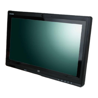
IEI Technology AFL2-W15A-N270 User Manual (141 pages)
Intel Atom N270 CPU, Touchscreen Gigabit Etherner, USB, Audio, RS-232/422/485, SATA RoHS Compliant, IP 64 Protection
Brand:
IEI Technology
| Category:
Touch Panel
| Size: 4 MB
Table of Contents
Table of Contents
4
1 Introduction
13
Overview
14
Figure 1-1: AFL2-W15A-N270
14
Model Variations
15
Features
15
Table 1-1: Model Variations
15
External Overview
16
Figure 1-2: Front Panel
16
Front Panel
16
Rear Panel
16
Bottom Panel
17
Figure 1-3: Rear Panel
17
Internal Overview
18
Figure 1-4: AFL2-W15A-N270 Bottom Panel
18
Specifications
19
Table 1-2: System Specifications
20
Dimensions
21
Figure 1-5: Dimensions
21
2 Installation
22
Unpack the Panel Pc
24
Packing List
24
Hard Drive Installation
25
Table 2-1: Packing List
25
Figure 2-1: HDD Access Panel Retention Screws
26
Figure 2-2: HDD/CF Card Brackets Retention Screws
26
Figure 2-3: HDD Bracket Retention Screws
27
Figure 2-4: HDD Installation
27
Compactflash® Installation
28
Figure 2-5: Compactflash® Slot Location
28
Figure 2-6: Compactflash® Install
28
Usb Dongle Installation
29
Cover Removal
29
Figure 2-7: USB Dongle Installation
29
Figure 2-8: Plastic Back Cover Retention Screws
30
Jumper Settings
31
Figure 2-9: Internal Aluminum Cover Retention Screws
31
Access the Jumpers
32
CF Card Setup
32
Table 2-2: AFL2-W15A-N270 Jumpers
32
Table 2-3: CF Card Setup Jumper Settings
32
Clear CMOS Jumper
33
Figure 2-10: CF Card Setup Jumper Location
33
COM 1 Port Pin 9 Select
34
Figure 2-11: Clear CMOS Jumper Location
34
Table 2-4: Clear CMOS Jumper Settings
34
COM 3 Port Pin 9 Select
35
Figure 2-12: COM1 Pin 9 Setting Jumper Location
35
Table 2-5: COM1 Pin 9 Setting Jumper Settings
35
COM3 RX Function Select Jumper
36
Figure 2-13: COM3 Pin 9 Setting Jumper Location
36
Table 2-6: COM3 Pin 9 Setting Jumper Settings
36
COM3 RS-232/422/485 Serial Port Select Jumper
37
Figure 2-14: COM3 RX Function Select Jumper Location
37
Table 2-7: COM3 RX Function Select Jumper Settings
37
COM3 TX Function Select Jumper
38
Figure 2-15: COM3 RS-232/422/485 Serial Port Select Jumper Location
38
Table 2-8: COM3 RS-232/422/485 Serial Port Select Jumper Settings
38
COM3 RS-422 and RS-485 Pinouts
39
Figure 2-16: COM3 TX Function Select Jumper Location
39
Table 2-10: RS-422 Pinouts
39
Table 2-11: RS-485 Pinouts
39
Table 2-9: COM3 TX Function Select Jumper Settings
39
Mounting the System
40
Arm Mounting
40
Figure 2-17: Arm Mount Retention Screw Holes
41
Figure 2-18: Arm Mounting (ARM-11-RS)
42
Panel Mounting
42
Figure 2-19: Cutout
43
Figure 2-20: Tighten the Panel Mounting Clamp Screws
44
Stand Mounting
44
Figure 2-21: Stand Mounting (Stand-A19)
45
Figure 2-22: Wall Mount
45
Wall Mounting
45
Figure 2-23: Wall-Mounting Bracket
46
Figure 2-24: Chassis Support Screws
47
Bottom Panel Connectors
48
Figure 2-25: Secure the Panel PC
48
Figure 2-26: AFL2-W15A-N270 Bottom Panel
48
Figure 2-27: LAN Connection
49
LAN Connection
49
Serial Device Connection
49
Figure 2-28: Serial Device Connector
50
Figure 2-29: USB Device Connection
50
USB Device Connection
50
Figure 2-30: VGA Connector
51
VGA Monitor Connection
51
Power Connection
52
Driver Installation
52
3 Bios Setup
53
Introduction
54
Starting Setup
54
Using Setup
54
BIOS Menu Bar
55
Getting Help
55
Table 3-1: BIOS Navigation Keys
55
Unable to Reboot after Configuration Changes
55
Main
56
BIOS Menu 1: Main
56
System Overview
56
Advanced
57
BIOS Menu 2: Advanced
57
System Date [XX/XX/XX]
57
System Time [XX:XX:XX]
57
CPU Configuration
58
BIOS Menu 3: CPU Configuration
58
Hyper Threading Technology [Enabled]
58
IDE Configuration
59
BIOS Menu 4: IDE Configuration
59
ATA/IDE Configurations [Compatible]
59
IDE Master, IDE Slave
60
BIOS Menu 5: IDE Master and IDE Slave Configuration
60
Auto-Detected Drive Parameters
60
Legacy IDE Channels [SATA Pri, PATA Sec]
60
Type [Auto]
61
Block (Multi Sector Transfer) [Auto]
62
Lba/Large Mode [Auto]
62
PIO Mode [Auto]
62
32Bit Data Transfer [Enabled]
63
Auto]
63
DMA Mode [Auto]
63
Super IO Configuration
64
BIOS Menu 6: Super IO Configuration
64
Serial Port1 Address [3F8/IRQ4]
64
Serial Port2 Address [2F8/IRQ3]
64
Serial Port3 Address [3E8]
65
Serial Port3 IRQ [10]
65
Hardware Health Configuration
66
BIOS Menu 7: Hardware Health Configuration
66
Monitored Values
66
Power Configuration
67
BIOS Menu 8: Power Configuration
67
ACPI Settings
68
BIOS Menu 9: ACPI Settings
68
Suspend Mode [S1(POS)]
68
APM Configuration
69
BIOS Menu 10: APM Configuration
69
Power Button Mode [On/Off]
69
Restore on AC Power Loss [Last State]
69
Resume on Keyboard/Mouse [Disabled]
70
Resume on Ring [Disabled]
70
Resume on Touch Panel [Disabled]
70
Remote Access Configuration
71
Resume on LAN [Enabled]
71
Resume on RTC Alarm [Disabled]
71
BIOS Menu 11: Remote Access Configuration
72
Remote Access [Disabled]
72
Serial Port Number [COM1]
72
Base Address, IRQ [3F8H, 4]
73
Redirection after BIOS POST [Always]
73
Serial Port Mode [115200 8,N,1]
73
USB Configuration
74
BIOS Menu 12: USB Configuration
74
Terminal Type [ANSI]
74
USB Devices Enabled
74
Legacy USB Support [Enabled]
75
USB 2.0 Controller [Enabled]
75
USB Function [Enabled]
75
USB2.0 Controller Mode [Hispeed]
75
IEI Feature
76
BIOS Menu 13: IEI Feature
76
Auto Recovery Function [Disabled]
76
Pci/Pnp
77
BIOS Menu 14: Pci/Pnp Configuration
77
IRQ# [Available]
77
DMA Channel# [Available]
78
Boot
79
BIOS Menu 15: Boot
79
Reserved Memory Size [Disabled]
79
Boot Settings Configuration
80
BIOS Menu 16: Boot Settings Configuration
80
Quick Boot [Enabled]
80
Quiet Boot [Enabled]
80
Addon ROM Display Mode [Force BIOS]
81
Boot from LAN Support [Disabled]
81
Bootup Num-Lock [On]
81
Boot Device Priority
82
BIOS Menu 17: Boot Device Priority Settings
82
Spread Spectrum Mode [Disabled]
82
Hard Disk Drives
83
Security
83
BIOS Menu 18: Hard Disk Drives
83
BIOS Menu 19: Security
83
Advanced Chipset Settings
84
Change Supervisor Password
84
Change User Password
84
North Bridge Configuration
85
BIOS Menu 20: Advanced Chipset Settings
85
BIOS Menu 21: North Bridge Configuration
85
DVMT Mode Select [DVMT Mode]
86
Internal Graphics Mode Select [Enable, 8 MB]
86
Memory Hole [Disabled]
86
Boot Display Device [Auto]
87
DVMT/FIXED Memory [Maximum DVMT]
87
LVDS Panel Type [By H/W]
87
South Bridge Configuration
87
BIOS Menu 22:South Bridge Configuration
88
Audio Controller [Auto]
88
Spread Spectrum Clock [Disabled]
88
Exit
89
BIOS Menu 23:Exit
89
Discard Changes
89
Discard Changes and Exit
89
Load Optimal Defaults
89
Save Changes and Exit
89
Load Failsafe Defaults
90
4 System Maintenance
91
System Maintenance Introduction
92
Motherboard Replacement
92
Memory Module Replacement
92
Figure 4-1: SO-DIMM Module Installation
92
A Safety Precautions
93
A.1 S Afety P Recautions
94
General Safety Precautions
94
Safety Precautions
94
Anti-Static Precautions
95
Maintenance and Cleaning
96
Maintenance and Cleaning Precautions
96
Product Disposal
96
Cleaning Tools
97
B One Key Recovery
98
B.1 O Ne K Ey R Ecovery I Ntroduction
99
Figure B-1: IEI One Key Recovery Tool Menu
99
One Key Recovery Introduction
99
System Requirement
100
Supported Operating System
101
B.2 S Etup P Rocedure for W Indows
102
Hardware and BIOS Setup
102
Setup Procedure for Windows
102
Create Partitions
103
Figure B-2: Launching the Recovery Tool
103
Figure B-3: Recovery Tool Setup Menu
104
Figure B-4: Command Mode
104
Figure B-5: Partition Creation Commands
105
Install Operating System, Drivers and Applications
106
Build-Up Recovery Partition
107
Figure B-6: Launching the Recovery Tool
107
Figure B-7: System Configuration for Windows
107
Figure B-8: Build-Up Recovery Partition
108
Figure B-9: Press any Key to Continue
108
Create Factory Default Image
109
Figure B-10: Press F3 to Boot into Recovery Mode
109
Figure B-11: Recovery Tool Menu
109
Figure B-12: about Symantec Ghost Window
110
Figure B-13: Symantec Ghost Path
110
Figure B-14: Select a Local Source Drive
111
Figure B-15: Select a Source Partition from Basic Drive
111
Figure B-16: File Name to Copy Image to
112
Figure B-17: Compress Image
112
Figure B-18: Image Creation Confirmation
113
Figure B-19: Image Creation Process
113
Figure B-20: Image Creation Complete
113
B.3 S Etup P Rocedure for L Inux
114
Figure B-21: Press any Key to Continue
114
Setup Procedure for Linux
114
Figure B-22: Partitions for Linux
115
Figure B-23: System Configuration for Linux
116
Figure B-24: Access Menu.lst in Linux (Text Mode)
116
B.4 R Ecovery T Ool F Unctions
117
Figure B-25: Recovery Tool Menu
117
Recovery Tool Functions
117
Figure B-26: Recovery Tool Main Menu
118
Factory Restore
119
Figure B-27: Restore Factory Default
119
Figure B-28: Recovery Complete Window
119
Backup System
120
Figure B-29: Backup System
120
Figure B-30: System Backup Complete Window
120
Figure B-31: Restore Backup
121
Figure B-32: Restore System Backup Complete Window
121
Restore Your Last Backup
121
Figure B-33: Symantec Ghost Window
122
Manual
122
B.5 O Ther I Nformation
123
Other Information
123
Using AHCI Mode or Ali M5283 / VIA VT6421A Controller
123
System Memory Requirement
125
CBIOS Options
126
Appendix C
127
D Terminology
129
E Watchdog Timer
133
Example Program
135
F Hazardous Materials Disclosure
136
Hazardous Materials Disclosure Table for IPB Products Certified as Rohs Compliant under 2002/95/EC Without Mercury
137
G International Standards Compliance
140
Fcc
141
CCC
141
G.1 en 60601-1, en 60601-2
141
Advertisement
Advertisement
Related Products
IEI Technology afl2-w15b-h61
IEI Technology AFL2-W15A-N270/R/2G-R20
IEI Technology AFL2-W15A-N270/R-EM/1G-R20
IEI Technology AFL2-W19A-H61 Series
IEI Technology AFL2-W19AB-H61-i5/R-R11
IEI Technology AFL2-W19A-H61-i5/PC-R11
IEI Technology AFL2-W19AB-H61-i5/PC-R11
IEI Technology AFL2-W19A-H61-i3/R-R11
IEI Technology AFL2-W19A-H61-i3/PC-R11
IEI Technology AFL2-W19AB-H61-P/R-R11
IEI Technology Categories
Motherboard
Touch Panel
Computer Hardware
Single board computers
Desktop
More IEI Technology Manuals
Login
Sign In
OR
Sign in with Facebook
Sign in with Google
Upload manual
Upload from disk
Upload from URL