Sign In
Upload
Manuals
Brands
Gilera Manuals
Scooter
Nexus 500
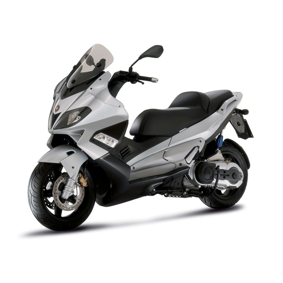
User Manuals: Gilera Nexus 500 Maxi Scooter
Manuals and User Guides for Gilera Nexus 500 Maxi Scooter. We have
2
Gilera Nexus 500 Maxi Scooter manuals available for free PDF download: Workshop Manual, User Manual
Gilera Nexus 500 Workshop Manual (400 pages)
Brand:
Gilera
| Category:
Scooter
| Size: 12 MB
Table of Contents
Index of Topics
5
Characteristics
6
Maintenance Rules
7
Safety Rules
7
Dimensions and Mass
8
Vehicle Identification
8
Weight
8
Capacities
9
Electrical System
9
Frame and Suspensions
9
Braking Plant Installation
10
Wheels and Tyres
10
Tightening Torques
11
Table of Contents
12
Assembly Clearances
13
Cylinder - Piston Assy
13
Muffler Retainer
13
Notice of Technical Servicing
13
Overhaul Data
13
Categories of Coupling
14
Crankcase - Crankshaft - Connecting Rod
14
Height at Which the Diameter Should be Measured
14
Piston Rings
14
Crankshaft Alignment
15
Diameter of Crankshaft Bearings
15
Max. Admissible Displacement
15
Axial Clearance between Crankshaft and Connecting Rod
16
Slot Packing System
16
Base Gasket Thickness
17
Products
17
Tooling
18
Tools
19
Maintenance
30
After 1,000 Km or 4 Months
31
Every 2 Years
31
Every 3,000 Km
31
Maintenance Chart
31
After 12,000 Km or 24 Months and 60,000 Km
32
After 18,000 Km and after 54,000 Km
32
After 6,000 Km or 12 Months
32
After 24,000 Km
33
After 30,000 Km, 42,000 Km and 66,000 Km
33
After 36,000 Km
33
After 48,000 Km
34
After 72,000 Km
34
Check and Replacement
35
Hub Oil
35
Spark Plug
35
Air Filter
37
Engine Oil
38
Engine Oil Filter
39
Engine Oil Drainage Plug
40
Checking the Valve Clearance
41
Cooling System
41
Oil Pressure Warning Light
41
Level Check
42
Braking System
43
Top-Up
43
Headlight Adjustment
44
Checking the End Compression Pressure
45
Components Arrangement
48
Diagnostic Socket
48
Wiring Colour Chart
48
H.V. Coil
49
Overturn Sensor
49
Saddle Opening ECU Remote Control
49
Electronic Control Unit ECU
50
Immobiliser Decoder
50
Relays and Diode Group
50
Conceptual Diagrams
51
Ignition
51
Voltage Regulator
51
Headlights and Automatic Starter Section
53
Light and Flashing Light Bulbs Section
53
Battery Recharge and Starting
54
Level Indicators and Enable Signals Section
55
Safety Switches and Level Indicator Section
55
Battery Recharge Circuit
56
Checks and Inspections
56
Recharge System Voltage Check
56
Stator Check
56
Lights List
57
Look for any Leakage
57
Maximum Current Output Check
57
Voltage Regulator/Rectifier
57
Fuses
58
Dashboard
59
Fuse Holder
59
Data Check Function
62
Commissioning Sealed Batteries
63
Sealed Battery
63
Dry-Charge Battery
64
Check the Signal
66
Phonic Wheel
66
Ecu
67
Receiver Control Unit for Saddle Opener
68
Seat Opening Receiver
68
Engine Rev. Sensor
69
Analogue Odometer
70
Remote Seat Opening
70
Battery Replacement
71
Programming
71
Zeroing
71
Engine from Vehicle
73
Exhaust Assy. Removal
74
Removal of the Engine from the Vehicle
74
Engine
76
Automatic Transmission
77
Transmission Cover
77
Air Duct
78
Transmission Cover
78
Air Duct Filter
79
Removing the Driven Pulley Shaft Bearing
79
Transmission Cover
79
Baffle Roller
80
Plastic Roller
80
Refitting the Driven Pulley Shaft Bearing
80
Transmission Cover
80
Inspecting the Clutch Drum
81
Removing the Driven Pulley
81
Pin Retaining Collar
82
Removing the Clutch
82
Removing the Driven Half-Pulley Bearing
83
Inspecting the Driven Fixed Half-Pulley
84
Inspecting the Driven Sliding Half-Pulley
84
Refitting the Driven Half-Pulley Bearing
84
Refitting the Driven Pulley
85
Inspecting the Clutch Spring
86
Clutch Ring Nut
87
Refitting the Clutch
87
Drive-Belt
88
Removing the Driving Pulley
88
Inspecting the Rollers Case
89
Installing the Roller Container
91
Refitting the Driving Pulley
91
Installing the Fixed Driving Half-Pulley
92
Driving Pulley Nut
93
Refitting the Transmission Cover
93
End Gear
95
Removing the Hub Cover
95
Removing the Wheel Axle
95
Transmission Cover
95
Removing the Hub Bearings
96
Removing the Wheel Axle Bearings
96
Transmission Cover
97
Inspecting the Hub Cover
98
Inspecting the Hub Shaft
98
Refitting the Hub Cover Bearings
100
Refitting the Hub Bearings
101
Flywheel Cover
102
Removing the Flywheel Cover Components
104
Removing the Stator
104
Inspecting the Cover Components
107
Refitting the Stator
109
Refitting the Flywheel Cover Components
110
Refitting the Flywheel Cover
113
Battery
114
Flywheel and Starting
114
Starter Motor
114
Start-Up Remote Control Switch
115
Starter Transmission
115
Removing the Flywheel Magneto
117
Removing the Starter Motor
117
Inspecting the Flywheel Components
121
Starter Gear Rim
121
Intermediate Gear
122
Refitting the Free Wheel
122
Refitting the Intermediate Gear
123
Refitting the Flywheel Magneto
124
Cylinder Assy. and Timing System
126
Refitting the Starter Motor
126
Removing the Intake Manifold
127
Removing the Rocker-Arms Cover
127
Removing the Timing System Drive
128
Removing the Cam Shaft
130
Removing the Cylinder Head
131
Removing the Valves
132
Removing the Cylinder - Piston Assy.
133
Inspecting the Small End
134
Inspecting the Wrist Pin
134
Inspecting the Piston
135
Inspecting the Piston Rings
136
Removing the Piston
137
Choosing the Gasket
138
Refitting the Cylinder
139
Refitting the Piston Rings
139
Inspecting the Cylinder Head
140
Inspecting the Timing System Components
140
Inspecting the Valve Sealings
141
Inspecting the Valve Housings
142
Inspecting the Valves
142
Minimum Admissible Diameter
142
Standard Diameter
142
Inlet
143
Inspecting the Valve Stem Guide Clearance
143
Outlet
143
Standard Valve Length
144
Inspecting the Cam Shaft
145
Refitting the Valves
145
Admissible Limits
146
Standard Height
146
Refitting the Head and Timing System Components
147
Exhaust / Intake Head Fixing Nuts
148
Coolant Temperature Sensor:
149
Camshaft Retaining Bracket Screws:
150
Prescribed Clearance
154
Refitting the Timing Chain
154
Valve Lifter Mass Stop Bell Fixing Screws
154
Inspecting the Radial Air Gap
156
Refitting the Rocker-Arms Cover
157
Refitting the Intake Manifold
158
Tappet Cover Fixing Screws
158
Splitting the Crankcase Halves
160
Removing the Crankshaft
161
Removing the Countershaft
162
Replacing the Countershaft Bearings
163
Inspecting the Crankshaft Components
165
Inspecting the Crankshaft Alignment
166
Max Admissible Displacement:
166
Inspecting the Crankcase Halves
167
Check the Bench Bush
169
Inspecting the Crankshaft Plain Bearings
169
Countershaft
170
Coupling Chart
170
Coupling the Semi-Shafts with the Semi-Chassis and Bushes
170
Refitting the Crankshaft
170
Gear Mounting on Crankshaft Screws
171
Bulkhead Screws for Oil Pump Housing Cover
172
Refitting the Crankcase Halves
172
Lubrication
174
Recommended Engine Oil
174
Sump Capacity
174
Head Lubrication Control Jet
175
General Characteristics
176
Principle Diagram
176
Diagnosis Guide
177
Standard Values
178
Oil Pressure Check
179
Oil Pump Removal
180
Injection
186
Circuit Layout
187
Standard Values with the Engine Idling
190
EMS Injection System
194
Precautions
196
Electronic Control Unit Side
197
Ems Controller
197
Terminals Setup
197
EMS Circuit Diagram
198
Immobilizer Decoder
198
Engine Does Not Start
199
Engine Start-Up Problems
199
Engine Does Not Return to the Idling Speed/Idling Speed too High
201
Engine Does Not Rev down
201
Exhaust Backfires When Decelerating
201
Engine Revs Irregularly
202
Irregular Progress of the Engine with Valve Slightly Open
202
Poor Performance at Full Throttle
202
Constant Supply Circuit Check
203
Decoder Master-Box Circuit
203
Engine Knocking
203
Presence of Knocking (Overhead Knocking)
203
Key-Switch Power Supply Circuit Check
205
YES Go to 11
205
YES Go to 2 no Go to 4
205
YES Go to 5 no Go to 6
206
YES Go to 7
206
Diagnostic Circuit
208
Injection Warning Light Circuit
209
YES Go to 6 no Go to 7
209
YES Go to 4
210
Checking Stored Failures
211
Self-Diagnosis System
211
Deleting Stored Failures
212
Fuel Supply System
212
Circuit Diagram
213
Removing the Injector
214
Injector Fixing Screw
215
Refitting the Injector
215
Circuit Check
217
Pump Supply Circuit
217
Refitting the Butterfly Valve
217
YES Go to 22
219
Circuit Leak Test
221
Pressure Regulator Check
222
Fuel Pump and Filter Check
223
Pump Electrics Check
226
Resistor Check
226
Fuel Filter Check
227
Pump Consumption Check
227
Pump Bracket Overhaul
228
Limit Values
229
Inspecting the Injector Circuit
232
Pump Bracket Installation
232
Injector - H.V. Coil
233
YES Go to 2
233
020481Y Control Unit Interface Wiring
234
Specific Tooling
234
YES Go to 8
234
YES Point 12
234
YES Go to 16 no Go to 17
235
Inspecting the Injector Hydraulics
236
Troubleshooting
237
Immobiliser Circuit
238
System Components
238
Virgin Circuit
239
LED Signals
241
Setting the Circuit
241
Checking Master-Box Data
242
Deterring Blink
242
Resetting the Circuit
242
Code 1
243
Diagnostic Codes
243
Code 2
244
Code 3
245
Code 4
246
Immobiliser LED Does Not Come on
246
Tachometer
247
Resistance of the Rpm Timing Sensor
250
HT Coil
252
Spark Advance
258
Coolant Temperature Sensor
259
Temperature Voltage
263
Intake Air Temperature Sensor
264
Pressure Sensor
270
Throttle Valve Opening Sensor
270
Resetting the Throttle Valve Position Signal (TPS Reset)
275
Zeroing the Throttle
275
Step Motor
277
Suspensions
283
Front Wheel Hub Overhaul
284
Removing the Front Wheel
284
Front Fork
286
Refitting the Front Wheel
286
Check Pump Unit
287
Check the Spring Length
287
Servicing Fork Stems
288
Servicing Tapered Bearing Seats
288
Refitting Stems on Fork Legs
290
Tube Size
290
Steering Bearing
293
Reassembly of Steering Tapered Bearing Seats
294
Reassembly of Tapered Bearing in Steering
295
Assembly Plate Mounting on Strut Support
295
Refitting the Rear Wheel
297
Removing the Rear Wheel
297
Swing-Arm
297
Shock Absorbers
298
Centre-Stand
299
Side Stand
300
Rear Brake Calliper
303
Front Brake Calliper
306
Rear Brake Disc
308
Disc Inspection
309
Front Brake Disc
310
Front Brake Pads
312
Rear - Combined
315
Brake Pump Technical Data
317
Replace the Pressure Distribution Valve
318
Electric Fan Check
322
Technical Specifications
322
System Sealing Check
323
Coolant Replacement
324
System Top-Up Instructions
324
Water Pump - Overhaul
325
Water Pump Ceramic Seal
326
Water Pump Cover Screws
326
Thermostat
327
Excessive System Pressure
328
Cooling Fluid Consumption
329
Oil in the Fluid
329
Chassis
330
Rear Handlebar Cover
331
Seat
331
Instrument Panel
332
Headlight Assy.
333
Frame Central Cover
334
Legshield
334
Knee-Guard
335
Removing the Ignition Key-Switch When on *Off*
337
Front Wheel Housing
338
Taillight Assy.
338
Footrest
339
License Plate Holder
340
Side Fairings
340
Helmet Bay
342
Rear Mudguard
342
Helmet Compartment
343
Spoiler
343
Fuel Tank
344
Rear Central Cover
345
Front Mudguard
346
Radiator Fan
346
Flyscreen
347
Handles and Top Side Fairings
347
Pilot Lights Kit
348
Lower Cover
349
Pre-Delivery
350
Aesthetic Inspection
351
Safety Locks
351
Tightening Torques Inspection
351
Levels Check
352
Road Test
352
Static Test
352
Functional Inspection
353
Time
354
Crankcase
356
Crankshaft
357
Cylinder Assy.
358
Cylinder Head Assy.
359
Rocker Arms Support Assy
360
Rocking Lever Support Unit
360
Cylinder Head Cover
361
Driven Pulley
363
Oil Pump
364
Final Gear Assy
365
Final Reduction Gear Assembly
365
Driving Pulley
366
Flywheel Magneto
368
Butterfly Valve
369
Throttle Body
369
Exhaust Pipe
370
Air Cleaner
371
Frame
372
Side/Central Stand
373
Front Shield - Spoiler
374
Legshield Spoiler
374
Central Cover
375
Central Frame Cover
375
Mudguard
376
Handlebar Covers
378
Handlebar Components
379
Saddle
380
Locks
381
Turn Signal Lights
382
Front Wheel
384
Grease Tone Wheel or Drive
384
Rear Wheel
385
Fuel Pump
386
Electric Devices
387
Helmet Compartment
391
Rear Side Fairings
392
Front Suspension
393
Rear Suspension
394
Brake System
396
Windscreen
397
Advertisement
Gilera Nexus 500 User Manual (110 pages)
Brand:
Gilera
| Category:
Scooter
| Size: 1 MB
Table of Contents
Table of Contents
5
Vehicle
7
Dashboard
9
Instruments
11
Indicator Unir
12
Clock
13
Digital Lcd Display
14
Maintenance Icons
15
Setting the Total and Trip Odometers
15
Setting the Date Function
16
MODE* Button
16
Key Switch
17
Locking the Steering Wheel
18
Releasing the Steering Wheel
18
Switch Direction Indicators
18
Horn Button
19
Light Switch
19
Emergency Flashing Light Button
20
Start-Up Button
20
Engine Stop Button
21
The Immobilizer System
21
Keys
22
Immobilizerdevice Enabled Indicator Led
23
Operation
23
Programming the Immobilizer System
24
Saddle Opening Remote Control
25
Remote Control Programming
25
Accessing the Fuel Tank
27
Power Supply Socket
28
The Saddle
29
Opening the Saddle to Access the Helmet Compartment by Remote Control
29
Identification
31
Adjusting the Windscreen
32
Use
35
Checks
36
Tyre Pressure
37
Shock Absorbers Adjustment
38
Alignment Adjustment
39
Anti-Overturning Sensor
39
Running in
40
Starting up the Engine
40
Precautions
42
Difficult Start up
43
Stopping the Engine
43
Stand
44
Automatic Transmission
46
Safe Driving
46
Maintenance
49
Engine Oil Level
50
Engine Oil Level Check
50
Engine Oil Top-Up
51
Warning Light (Insufficient Oil Pressure) (03_03
51
Engine Oil Change
52
Hub Oil Level
53
Tyres
55
Spark Plug Dismantlement
57
Removing the Air Filter
58
Cooling Fluid Level
61
Checking the Brake Oil Level
62
Braking System Fluid Top up
63
Battery
64
Use of a New Battery
64
Checking the Electrolyte Level
65
Long Periods of Inactivity
66
Fuses
67
Front Light Group
72
Headlight Adjustment
74
Front Direction Indicators
75
Rear Turn Indicators
75
Number Plate Light
76
Helmet Compartment Lighting Bulb
76
Brake Light
77
Rear-View Mirrors
78
Front and Rear Disc Brake
79
Puncture
80
Periods of Inactivity
81
Cleaning the Vehicle
81
Technical Data
87
Kit Equipment
93
Spare Parts and Accessories
95
Programmed Maintenance
97
Scheduled Maintenance Table
98
Advertisement
Related Products
Gilera NEXUS 300 i.e.
Gilera Nexus 500 euro 3
Gilera Nexus 125 ie 2019
Gilera Nexus 250 i.e.
Gilera Nordwest
Gilera 2008 MSS Nexus
Gilera 2008 MSS Nexus 300 i.e. E3
Gilera 633499
Gilera 633721
Gilera 633728
Gilera Categories
Scooter
Motorcycle
Engine
More Gilera Manuals
Login
Sign In
OR
Sign in with Facebook
Sign in with Google
Upload manual
Upload from disk
Upload from URL