Sign In
Upload
Manuals
Brands
ELCOM Manuals
Payment Terminal
euro-500tx handy
ELCOM euro-500tx handy Manuals
Manuals and User Guides for ELCOM euro-500tx handy. We have
3
ELCOM euro-500tx handy manuals available for free PDF download: Service Manual, User Manual
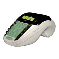
ELCOM euro-500tx handy Service Manual (80 pages)
Brand:
ELCOM
| Category:
Cash Register
| Size: 7 MB
Table of Contents
Table of Contents
3
1 Introduction
9
Euro-500TX Handy Technical Parameters
9
System Configuration
9
Block Chart of ECR Euro-500TX
9
Fig. 1.1: Block Chart of ECR Euro-500TX
9
2 Circuit Schemes and Functions
10
Power Supply Circuits
10
External Power Supply
10
Primary Power Supply
10
The +5 V Power Source (VCC) and the NMI Signal Generator
10
Fig. 2.1 Primary Power Supply
10
Fig. 2.2 +5 V Power Supply and the NMI Signal Generator
10
The +5 V Power Source (VCC1)
11
Power Supply for the Printer Performance Circuits (VH)
11
Accumulator Voltage to the VH Voltage Converter
11
Fig. 2.3 VCC1 Power Supply
11
Fig. 2.4 VH Power Supply
11
Fig. 2.5 Accumulator Voltage Converter Circuit
11
Nimh Accumulator Charging Circuit
12
Fiscal Memory Power Supply Circuits
12
Power Supply Voltages Characteristics
12
Fig. 2.6 Nimh Accumulator Charging Circuit
12
Fig. 2.7 FM Power Supply Circuits
12
The Microcontroller and Its Support Circuits
13
The E-500TXN Microcontroller
13
Fig. 2.8 the E-500TXN Microcontroller
13
Tab. 2.1 Description of the E-500TXN Microcontroller Signals
13
Memory Circuits
15
Fig. 2.9 Memory Connexion
15
Start-Up and Turning off of the System
16
Real-Time Circuit
16
Fig. 2.10 Reset Controller
16
Fig. 2.11 Standby Controller
16
Fig. 2.12 Real-Time Circuit
16
I/O Circuits
17
Printing Control Circuits
17
Fig. 2.13 Printer Control Signals
17
Fig. 2.14 Printer Motor Control and Control of the Journal Winding Motor
17
Keyboard
18
Fig. 2.15 Journal Winding Motor Connexion
18
Fig. 2.16 Receipt Paper Tape Detection in the Printer
18
Fig. 2.17 Journal Paper Tape Detection in the Printer
18
Fig. 2.18 Measuring the Printer Head Temperature
18
Fig. 2.19 Detecting the Printer Head Position
18
Fig. 2.20 Connectors for Fitting the Interconnect PCB
18
Tab. 2.2 Winding Motor Connexion
18
Fig. 2.21 Keyboard Connexion Scheme
19
Fig. 2.22 Signal Chart on the 7442 Decoder (Outlets a - C)
19
Fig. 2.23 Signal Chart on the 7442 Decoder (Outlets 0 - 7)
19
Displays
20
Fig. 2.24 the Display Control in the Euro-500TX Handy
20
Communication Circuits
21
Fig. 2.25 Segment LCD and the NJU6432B Display Controller Connexion
21
Fig. 2.26 NJU6432B Display Controller Connexion
21
Fig. 2.27 View on the Display Placement in Euro-500TX Handy
22
Fig. 2.28 View on the Display Placement in Greek Version of Euro-500TX Handy
22
Fig. 2.29 Communication Circuits and the External PC Keyboard Interface
23
Connexion of Fiscal Memory Circuits
24
Fig. 2.30 Connectors for Fitting the Connectors PCB
24
Fig. 2.31 FM Connexion
24
Other Circuits
25
Fig. 2.32 Power Supply Voltage Checking Circuits
25
Fig. 2.33 Buzzer Circuit
25
Fig. 2.34 Drawer Opening Circuit and the Opening Signal Chart
25
Fig. 2.35 the Circuit Reading the Keyboard and Jumpers' Status
25
Fig. 2.36 Individual ECR Connectors Pin Connexion
26
Fig. 2.37 Connector PCB Connexion
26
3 Thermal Printer LT1320
27
Basic Specification
27
Thermal Head
27
Thermal Head Composition
27
Fig. 3.1 Thermal Head Connexion
27
Data Processing in the Printing Head
28
Printing Data and Their Position
28
Thermistor Specification
28
Time Diagram
28
Fig. 3.2 Printing Data Placement
28
Fig. 3.3 Time Diagram
28
Tab. 3.1 Gates (Strobes) Placement
28
Paper Feeding
29
Step-Motor Specification
29
Excitation Sequence
29
Control Circuit
29
Fig. 3.4 Performance Signals of the Step-Motor
29
Fig. 3.5 Control Circuit
29
Tab. 3.2 Step-Motor Specification
29
Tab. 3.3 Excitation Sequence Signals
29
Printing Head Position Sensor
30
Paper Tape Presence Detectors
30
Overall Time Diagram
30
Fig. 3.6 Outer Part of the Head Position Sensor
30
Fig. 3.7 Sensor Circuit on the Main PCB
30
Fig. 3.8 External Sensor Circuit on the Interconnect PCB
30
Fig. 3.9 Overall Time Diagram
30
Printer Connectors
31
Printing Head Connectors
31
Fig. 3.10 Placement of Thermal Head Connector
31
Tab. 3.4 Connector Types Placed on the Printer
31
Tab. 3.5 Thermal Head Connector Pin Description
31
Terminal for the Sensors
32
Cleaning of the Printing Head
32
Fig. 3.11 Sensor Connexion to the Connector
32
Tab. 3.6 Sensor Terminal Pin Description
32
4 Reinstallation of Individual Modules
33
ECR Disassembly
33
Fig. 4.1 Rough ECR Cover Disassembly Chart
33
Tab. 4.1 Table of Shown Parts
33
Fig. 4.2 Releasing of the Keyboard
34
Fig. 4.3 Pulling out the Middle Cover
34
Reinstallation of Accumulator
35
Printer Reinstallation
35
Fig. 4.4 Fixation and Localisation of the Accumulators
35
Tab. 4.2 Table of Shown Parts
35
Fig. 4.5 Printer Reinstallation at Segment LCD
36
Tab. 4.3 Table of Shown Parts
36
Fig. 4.6 Printer Reinstallation at Alphanumerical LCD
37
Tab. 4.4 Table of Shown Parts
37
Motor Reinstallation
38
Fig. 4.7 Motor Reinstallation
38
Fig. 4.8 Bottom View of Motor Cover
38
Tab. 4.5 Table of Shown Parts
38
Reinstallation of the Main PCB
39
EPROM Reinstallation
39
Fig. 4.9 Fitting of the Main PCB
39
Tab. 4.6 Table of Shown Parts
39
Defective SRAM Replacement or Replacing the SRAM to Higher Capacity
40
Fig. 4.10 EPROM Chip on the Main PCB
40
Tab. 4.7 Table of Shown Parts
40
Nicd Accumulator Reinstallation
41
Reinstallation of the Keyboard or Individual Keys
41
Fig. 4.11 Nicd Accumulator on the Main PCB
41
Tab. 4.8 Table of Shown Parts
41
Fig. 4.12 Keyboard Disassembly
42
Fig. 4.13 Individual Keyboard Keys
42
Tab. 4.9 Table of Shown Parts
42
Reinstallation of Displays
43
Reinstallation of Displays for the ECR Euro-500TX Handy
43
Fig. 4.14 Display Reinstallation
43
Tab. 4.10 Table of Shown Parts
43
Reinstallation of Displays for the Greek Version of Euro-500TX Handy
44
Fig. 4.15 Display Reinstallation in the Greek Version of Euro-500TX Handy
44
Tab. 4.11 Table of Shown Parts
44
ECR Connectors
45
Connectors Placed on the Main PCB
45
Connector for External Devices
45
Fig. 4.16 ECR Connectors
45
Fig. 4.17 Connectors PCB Placement
45
Segment LCD Backlight Installation
46
Connection of the External ECR Drawer
46
Fig. 4.18 Segment LCD Backlight Installation
46
Fig. 4.19 Overlay for PCB for the LCD with Backlight
46
Tab. 4.12 Table of Shown Parts
46
Fig. 4.20 Connection of the External ECR Drawer
47
Fig. 4.21 Modular Jack 4×4 Connexion
47
Connection of the External Keyboard
48
Connection of Euro-500TX Handy to the PC Using the RS-232 Interface
48
Fig. 4.22 Connection of the External Keyboard
48
Fig. 4.23 Mini DIN PS/2 Connector
48
Fig. 4.24 PC Communication Cable Connexion
48
Scanner and Scales Connection to the Euro-500TX Handy Via the RS-232 Interface
49
Fig. 4.25 Scanner/Scales Communication Cable Connexion
49
Tab. 4.13 Pin Connexion for the Scanner
49
Tab. 4.14 Pin Connexion for the Scales
49
5 ECR Tests
50
Display Tests
50
Fig. 5.1 the Segment LCD Area Division
50
Tab. 5.1 the ECR Euro-500TX Handy Tests
50
Printer Tests
51
Printing Test
51
Thermal Head Position Test
51
Paper Presence Sensor Test
51
Keyboard Tests
52
Keyboard Test 1
52
Keyboard Test 2
52
Fig. 5.2 the Keyboard Keys Arrangement
52
Communication Interfaces Tests
53
RS-232 Serial Interface Test for PC
53
Fig. 5.3 the Correct Sequence for Pressing the Keys at Keyboard Test 2
53
Fig. 5.4 Modular Jack 6×6 Terminal Connector
53
RS-232 Serial Interface Test for Scanner and Scales
54
External PC Keyboard Interface Test
54
Fig. 5.5 Mini DIN PS/2 Terminal Connector
54
ECR Drawer Test
55
Fiscal Memory Tests
55
FM Data Reading Tests
55
Tab. 5.2 FM Partitioning for Individual Tests
55
FM Data Writing Tests
56
FM Working Voltages Test
56
FM Control Signals Test 1
56
FM Control Signals Test 2
57
EPROM Checksum Test
57
Accumulator Tests
57
Accumulator Status Test
57
VCC1 Power Supply Test
58
6 Troubleshooting
59
Power Supply Troubleshooting
59
Microprocessor Troubleshooting
60
Printing Troubleshooting
61
Display Troubleshooting
63
Keyboard Troubleshooting
63
Communication Troubleshooting
64
Real-Time and Date Troubleshooting
64
Miscellaneous Troubleshooting
64
7 Ordering and Listing of Spare Parts
66
ECR Parts Classification
66
Arrangement and Listing of Main PCB Parts
66
Fig. 7.1 Main PCB Top Overlay
66
Fig. 7.2 Main PCB Bottom Overlay
67
Tab. 7.1 Bill of Material for the Main PCB
67
Arrangement and Listing of Keyboard Parts
75
Fig. 7.3 Keyboard PCB Top Overlay
75
Arrangement and Listing of Segment LCD Module
76
Fig. 7.4 Segment LCD Module Top and Bottom Overlay
76
Tab. 7.2 Bill of Material for the Keyboard PCB
76
Tab. 7.3 Bill of Material for the Segment LCD Module
76
Arrangement and Listing of Connectors PCB
77
Arrangement and Listing of Interconnecting PCB
77
Fig. 7.5 Connectors PCB Overlay
77
Fig. 7.6 Intercon PCB Top and Bottom Overlay
77
Tab. 7.4 Bill of Material for the Connectors PCB
77
Tab. 7.5 Bill of Material for the Intercon PCB
78
Advertisement
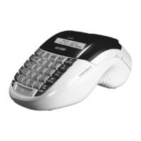
Elcom euro-500tx handy User Manual (72 pages)
Brand:
Elcom
| Category:
Cash Register
| Size: 1 MB
Table of Contents
Table of Contents
3
Introduction
7
Important
7
Basic Definitions
8
Logo
8
Department
8
Tax Level
8
Sales Units
8
Plu
8
Relationship between the Departments and Plus
8
Report
9
Bar Code
9
Bar Code Scanner
9
System Flags
9
Grand Totals
9
Cash Register Characteristics
11
Parts of the Cash Register, Basic Parameters
11
External Equipment Connectivity
12
The Euro-500T Handy/Euro-500TX Handy Keyboard
13
Displays Layout
15
Euro-500T/TX Handy Cashier Display Layout
15
Euro-500T/TX Handy Customer Display Layout
15
Switching the Display Back-Light on and Off
15
Mode Switch
16
Paper Ribbons Installation
16
Usage and Storage of Thermal Paper
18
Programming Manual
19
Initialisation
19
Recommended Procedure for Euro-500T/TX Handy Programming
19
Flags Programming
19
Initial Programming of System Flags
19
System Flags Correction
20
Printing Flags Values
20
Flag 1 - Number of Decimal Places, Method of Rounding, TAX System
20
Flag 2 - TAX Printing, Number of Logo Lines, Blank Lines
20
Flag 3 - Receipt Consecutive Number, Cash Register Number
21
Flag 4 - Required Operations
21
Flag 5 - Parameters of Serial Communication
21
Flag 6 - Printing Mode Setting
21
Flag 7 - Limit and Value of the Percent Add-On
22
Flag 8 - Limit and Value of the Percent Discount
22
Flag 9 - Time Setting
22
Flag 10 - Date Setting
22
Tax Rates Programming
22
Correction of the Tax Level Values
23
Printing of the Preprogrammed Tax Values
23
Receipt Logo Programming
23
Correction of the Logo Lines
24
Printing the Programmed Logo Lines
24
Cashier Programming
24
Correction of Cashiers
25
Printing of Cashier Values
25
Function Text Programming
25
Correction of Function Texts
25
Printing Function Texts Setting
26
Departments Programming
26
Correcting Departments
27
Printing Department Values
27
Sale Unit Programming
27
Correcting Programmed Sale Units
28
Printing Sale Unit Settings
28
Article Items (PLU) Programming
28
Setting up the Bar-Code Scanner
30
Quick PLU Price Programming
30
Quick PLU Stock Programming
30
Correction of Programmed Plus
31
Printing the Programmed Plus
31
Programming the Euro Currency
31
Stage Without Euro Currency
31
First Euro Currency Stage
31
Procedure for Entering the First Euro Stage
31
Second Euro Currency Stage
31
Third Euro Currency Stage
32
Entering Texts into ECR
32
Operation in Registration Mode
35
Recommended Procedures at the Beginning of the Day
35
Printing Modes
35
Status and Functions Required at the Beginning of Registration
35
Error Warning: the Clear Key
35
Cashier Log In: the Password Key
36
Cashier Log Out: the F E (Password) Key
36
Finalizing a Transaction: Cash, Cheque, Credit Keys
36
Samples of Basic Registration Procedures
36
Registration Using Departments
37
Basic Registration Using Departments
37
Registration Using Departments with Price Entry Using Keyboard
37
Registration Using Departments with Pre-Programmed Price
38
Registering Multiple Items Using Departments
38
Multiplying Items During Registration Using Departments
38
Registering Fractions of Items Using Departments
39
Double Multiplication of Items During Registration Using Departments
39
Single Item Sales Using into Departments
40
PLU Registration
40
Basic PLU Registration
41
Multiplication in PLU Registration
41
Individual PLU Registration
41
Overriding the Pre-Programmed PLU Price
41
Fractional PLU Registration
42
Double Multiplication in PLU Registration
42
Other Means of Registration
42
Registration Using Bar-Codes
42
Weight Entry by Electronic Scales
43
Registration Using an External PC Keyboard
43
PC ON-LINE Mode
43
Data Are Transmitted from a PC to the Cash Register
43
Data Are Transmitted from the Cash Register to PC
44
Clearing
45
Per Cent Surcharge and Discount
46
Per Cent Surcharge
46
Percent Discount
46
Reference Number and Customer Number
47
Received on Account
47
Paid out (Cash or Cheque)
47
Refunds
48
Registration Using the Euro Currency
49
Stage Without Euro
49
First Euro Currency Stage
49
Second Euro Currency Stage
50
Third Stage of the Euro
50
Reports
52
How to Print out Reports
52
Generated Reports
52
Report Contents
52
Department Report
52
PLU Report
52
Financial Report
53
Cashier Report
53
Total Daily "X" Report
53
Periodical "X" Report
53
Total Daily "Z" Report
53
Periodical "Z" Report
53
Samples of "X" Reports
54
How to Print "Z" Reports
56
Samples of "Z" Reports
56
Eurosoft Software for DOS
58
Eurosoft Basic Characteristics
58
Installation of the Eurosoft Software
58
Software Installation from Floppy Disk
58
Software Installation from CD
58
How to Start Eurosoft
59
Eurosoft Main Menu
59
Settings
59
Edit
60
Send
61
Receive
62
Receipt of Programmed Data from ECR to PC
62
Receipt of Sales Data from ECR to PC
63
Overview and Print
63
End Menu
63
Optional Accessories
64
Display Back-Light
64
Power Supply Cable for Supplying the Register from the Car
64
Cash Drawers
64
Digital Scales
65
Bar-Code Scanners
65
Optional Accessories
65
Helpful Advice
67
Information and Error Messages
67
Power Failure
69
Failures of Register as a Result of Interference in Power Network
69
What to Do in Case of "Recharge Battery" Signal
69
Self Tests
70
Self-Test of the Electronics and Display
70
Self-Test of the Printer
70
Self-Test of Keyboard
70
Service Codes of the ECR
70
ELCOM euro-500tx handy User Manual (65 pages)
Brand:
ELCOM
| Category:
Payment Terminal
| Size: 1 MB
Table of Contents
Table of Contents
3
Introduction
7
Important
7
Basic Definitions
8
Logo
8
Department
8
Tax Level
8
Sales Units
8
Plu
8
Relationship between the Departments and Plus
8
Bar Code
9
Bar-Code Scanner
9
System Flags
9
Cumulated Totals (Grandtotals)
9
Report
9
Cash Register Characteristics
10
Parts of the Cash Register, Basic Parameters
10
External Equipment Connectivity
11
The Euro-500T Handy/Euro-500TX Handy Keyboard
12
Key Names and Their Functions
13
Displays Layout
14
Euro-500T/TX Handy Cashier Display Layout
14
Euro-500T/TX Handy Customer Display Layout
14
Switching the Display Back-Light on and off
14
Mode Switch
15
Paper Ribbons Installation
15
Usage and Storage of Thermal Paper
17
Programming Manual
18
Initialisation
18
Recommended Procedure for Euro-500T/TX Handy Programming
18
Flags Programming
18
Initial Programming of System Flags
18
System Flags Correction
19
Printing Flags Values
19
Flag 1 - Number of Decimal Places, Method of Rounding, TAX System
19
Flag 2 - TAX Printing, Number of Logo Lines, Blank Lines
19
Flag 3 - Receipt Consecutive Number, Cash Register Number
20
Flag 4 - Required Operations
20
Flag 5 - Parameters of Serial Communication
20
Flag 6 - Printing Mode Setting
20
Flag 7 - Limit and Value of the Percent Add-On
21
Flag 8 - Limit and Value of the Percent Discount
21
Flag 9 - Time Setting
21
Flag 10 - Date Setting
21
Tax Rates Programming
21
Correction of the Tax Level Values
22
Printing of the Preprogrammed Tax Values
22
Receipt Logo Programming
22
Correction of the Logo Lines
23
Printing the Programmed Logo Lines
23
Cashier Programming
23
Correction of Cashiers
24
Printing of Cashier Values
24
Function Text Programming
24
Correction of Function Texts
24
Printing Function Texts Setting
25
Departments Programming
25
Correcting Departments
26
Printing Department Values
26
Sale Unit Programming
26
Correcting Programmed Sale Units
27
Printing Sale Unit Settings
27
Article Items (PLU) Programming
27
Setting up the Bar-Code Scanner
29
Quick PLU Price Programming
29
Quick PLU Stock Programming
29
Correction of Programmed Plus
30
Printing the Programmed Plus
30
Programming the Euro Currency
30
Stage Without Euro Currency
30
First Euro Currency Stage
30
Procedure for Entering the First Euro Stage
30
Second Euro Currency Stage
30
Third Euro Currency Stage
31
Entering Texts into ECR
31
Operation in Registration Mode
34
Recommended Procedures at the Beginning of the Day
34
Printing Modes
34
Status and Functions Required at the Beginning of Registration
34
Error Warning: the Clear Key
34
Cashier Log In: the Password Key
35
Cashier Log Out: the F E (Password) Key
35
Finalizing a Transaction: Cash, Cheque, Credit Keys
35
Samples of Basic Registration Procedures
35
Basic Registration Using Departments
36
Registration Using Departments with Price Entry Using Keyboard
36
Registration Using Departments with Pre-Programmed Price
37
Registering Multiple Items Using Departments
37
Multiplying Items During Registration Using Departments
37
Registering Fractions of Items Using Departments
38
Double Multiplication of Items During Registration Using Departments
38
Single Item Sales Using into Departments
39
PLU Registration
39
Basic PLU Registration
40
Multiplication in PLU Registration
40
Individual PLU Registration
40
Overriding the Pre-Programmed PLU Price
40
Fractional PLU Registration
41
Double Multiplication in PLU Registration
41
Other Means of Registration
41
Registration Using Bar-Codes
41
Weight Entry by Electronic Scales
42
Registration Using an External PC Keyboard
42
PC ON-LINE Mode
42
Data Are Transmitted from a PC to the Cash Register
42
Data Are Transmitted from the Cash Register to PC
43
Clearing
44
Per Cent Surcharge and Discount
45
Per Cent Surcharge
45
Percent Discount
45
Received on Account
46
Paid out (Cash or Cheque)
46
Refunds
47
Registration Using the Euro Currency
48
Stage Without Euro
48
First Euro Currency Stage
48
Second Euro Currency Stage
49
Third Stage of the Euro
49
Reports
51
How to Print out Reports
51
Generated Reports
51
Report Contents
51
Department Report
51
PLU Report
51
Financial Report
52
Cashier Report
52
Total Daily "X" Report
52
Periodical "X" Report
52
Total Daily "Z" Report
52
Periodical "Z" Report
52
Samples of "X" Reports
53
How to Print "Z" Reports
55
Samples of "Z" Reports
55
Euro2A Software
57
Optional Accessories
59
Display Back-Light
59
Power Supply Cable for Supplying the Register from the Car
59
Cash Drawers
59
Digital Scales
60
Bar-Code Scanners
60
Payment Terminal
61
Helpful Advice
62
Information and Error Messages
62
What to Do in Case of Power Failure
64
Power Failure
64
Failures of Register as a Result of Interference in Power Network
64
What to Do in Case of "Recharge Battery" Signal
64
Self Tests
65
Self-Test of the Electronics and Display
65
Self-Test of the Printer
65
Self-Test of Keyboard
65
Service Codes of the ECR
65
Advertisement
Advertisement
Related Products
ELCOM Euro-500TE
ELCOM Euro-50T Mini
Elcom Euro-500T Handy
ELCOM Euro-50TE Mini
ELCOM Euro-50iTE Mini
ELCOM Euro-500 Handy Series
ELCOM Euro-50
ELCOM Euro-150TE Flexy F
ELCOM Euro-150TX Flexy
ELCOM Euro-2500TX
ELCOM Categories
Cash Register
Intercom System
Touch terminals
Desktop
Industrial Equipment
More ELCOM Manuals
Login
Sign In
OR
Sign in with Facebook
Sign in with Google
Upload manual
Upload from disk
Upload from URL