Sign In
Upload
Manuals
Brands
Barco Manuals
Projector
SIM 5W
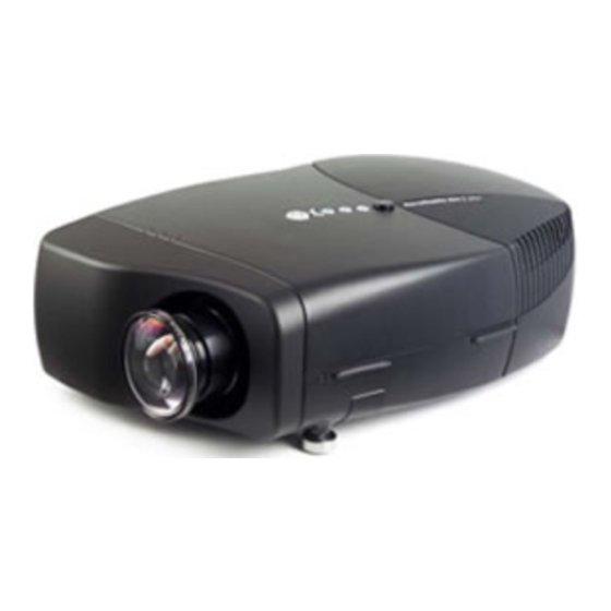
User Manuals: Barco SIM 5W Single-Chip DLP Projector
Manuals and User Guides for Barco SIM 5W Single-Chip DLP Projector. We have
1
Barco SIM 5W Single-Chip DLP Projector manual available for free PDF download: User Manual
Barco SIM 5W User Manual (195 pages)
Brand:
Barco
| Category:
Projector
| Size: 24 MB
Table of Contents
Table of Contents
5
User Guide
1
Disposal Information
3
1 Safety Instructions
9
Warnings
9
Note
9
2 Packaging and Dimensions
11
Unpacking
11
3 Installation Guidelines
13
Safety Warnings
13
Projector Position
14
Roll Possibilities
15
Airflow
16
Pitch Possibilities
16
Side Projection Limitations
16
Air Intake Vent
17
4 Installation
19
Battery Installation in the RCU
20
Lens Installation
21
Make Sure the Lens Lock Holder Is in the Left Position
22
The Female Jack on the Lens (A) Must be in Front of the Male Jack (B) Located in the Upper-Left Part of the Housing in
23
The Projector
23
In Case of a Scheimpflug Lens, Insert the Lens with the Adjustment Bolts Located in the Left and Bottom Position
23
Cleaning the Lens
24
The Lens Lock Handle Is Located on the Front Side of the Projector, Slide this Handle to the Right
24
Lens Range
25
Lens Formulas
25
Lens Shift Limitations
25
Off-Axis: Defining the Distance to Measure the %Off-Axis
26
Safe Shift Range Based on the Maximum Up/Down, Left/Right Directions
26
Lens Brightness
27
Projector Configuration
27
Connections
28
Connections Overview
28
Power Connection
28
Composite Video
29
Connections Overview
29
Rgb
30
S-Video
30
Composite Video Connection
30
S-Video Connection
30
Component Video
31
RGB Connections
31
Connecting to a DVI Connector
32
DVI
32
Introduction
32
Component Video Connection
32
DVI Input Connection
33
DVI HDCP Input Connection
34
DVI out Connection
34
Communications
35
Network Connections
35
PC Connection
35
Network Settings
36
Network Connection
36
Serial Connection
38
Serial Connection
39
RCU Terminology Overview
40
RCU Overview
40
Local Keypad Terminology Overview
41
Local Keypad Overview
41
Diagnose Leds
42
5 Setup
43
Powering up the Projector
43
Setting up the Remote Control Unit Address
43
Setting up the Projector Address (Only if Necessary)
44
Setting up the Orientation
45
Adjusting the Lens
46
Setup the Baud Rate for Serial Communication
48
Preferences
48
Automatic Startup
49
Language Setting
49
Change Password
50
Setup of Linked Projectors in a Multichannel System
51
6 Getting Started
55
Startup
55
Adjusting the Image
55
7 Advanced
57
Using the Menu
57
Using the Dialog Boxes
58
Source Selection
59
Composite Video
59
S-Video
60
Rgb-Yuv
61
DVI
62
Image
63
Image Settings
63
Setting the Brightness
63
Setting the Contrast
63
Color (Video Signals Only)
64
Tint (NTSC Video Signals Only)
64
Gamma
65
Phase (RGB Signals Only)
65
Sharpness (Video Signals Only)
65
Automatic Gain on Video
66
Gain Control on Video
66
Noise Reduction (Only for Video Signals)
66
Manual Gain Control on Video
67
Aspect Ratio
68
Common Non- Anamorphic Aspect Ratios in (Non-HDTV) DVD Sources
68
Anamorphic Aspect Ratios in (Non-HDTV) DVD Sources
68
Aspect Ratios in Native HDTV DVD Sources
68
Aspect Ratio for WUXGA (1920X1200)
69
Input Balance (RGB Signals Only)
72
Passive Infitec TM (Optional)
75
Image Files
76
Introduction to Image Files
76
Load File
77
Forced File Load
78
Auto Image
79
Edit File
79
Save as (Create a Custom File)
82
Copy
83
Rename File
83
Delete
84
Geometry
85
Geometry Files
85
Introduction
85
Geometry File Notation
85
Accessing the Geometry Menu
86
Geometry Distortions
86
The Screen Is Divided in 33X33 Regions
86
Geometry Levels
87
Load
88
Geometry Level Hierarchy
88
Accessing the Geometry Edit Menu
89
Edit
89
Geometry Edit Wizard
90
Geometry Edit Modes
92
Busy Message
92
Editing a Geometry File
94
2X2 Adjustment Points
94
Axis Link
101
Shift Adjustment
104
Transport Delay
106
Geometry: Shift
106
Transport Delay
107
Transport Delay Basic Principle
107
Sharpness
108
Geometry Reset
109
Reset All Levels
109
Restore to a Level
110
Geometry Restore Example : Restoring to a 9X9 Level
111
Rename a Geometry File
112
Copy a Geometry File
113
Delete a Geometry File
114
Lamps
115
Lamp Runtimes
115
Lamp Mode
116
Clo
117
The CLO Menu
117
CLO Mode
118
CLO Target in Normal Mode
119
CLO Targets
119
CLO Target in Infitec
120
Time of Day Target
121
Dimmer Control
122
Dimmer Set Positions
122
Linked CLO
122
Dimmer Presets
123
Manual Time of Day
125
Dimmer Limits
126
History
128
Reset Lamp Runtime
128
Clear Lamp Error
129
Lamp Runtime Warning
130
General
131
Identification
131
Pause
131
Freeze
132
Standby Timer
132
Desktop
133
Display Setup
134
Full Screen Synchronous Representation
134
Textbox
134
Menu Bar Position
135
Slider Box Position
136
Status Bar Position
136
Dynacolor
137
Introduction
137
The CIE Chromaticity Diagram
137
The Projector Color Gamut Is Defined by the Triangle Formed by the X, y Coordinates of Red Green and Blue
138
The Color Gamut of each Projector will Differ
138
Common Color Gamut
138
The Common Color Gamut
139
Enabling Dynacolor
141
Dynacolor Sets
142
Calibration for the Standard Mode (for Multiple Projectors)
143
Dynacolor Adjustments
143
Introduction
143
Common Color Values
145
Infitec Common Color Values
146
Brilliant Color TM Mode
147
Color Temperature
147
Introduction
149
Soft Edge
149
Soft Edge : Purpose
149
Soft Edge Basic Principle
149
Soft Edge Adjustments
150
Soft Edge : Adjustment Points
150
Soft Edge : Points Numbering, Top and Bottom Side Edges
151
Soft Edge : Points Numbering, Left and Right Side Edges
151
Accessing the Soft Edge Menu
152
Side Soft Edge Zone: Levels
152
Soft Edge : Level Hierarchy
152
Soft Edge Edit
153
The Soft Edge Edit Wizard
153
The Soft Edge Edit Modes
154
Creating/Editing a Soft Edge
155
Alpha Planes
163
Black Level
164
Introduction
164
Internal Black Level
165
Black Level : Double Brightness Compensation
165
Beta Planes
166
Blanking
167
Autoimage Setup
168
Sync Variance Limit
169
Installation
170
Edid
170
Internal Patterns
171
Outline
171
Hatch
171
Color Bars
171
Checkerboard
172
Hgbws
172
H Pattern
172
Convergence
172
Purity
173
Scaled Patterns
174
Scaled Patterns : Geometry
174
Scaled Patterns : Gray Levels
174
Scaled Patterns : Stereo Pattern
174
Formatter Patterns
175
Color Wheel Index
176
Service
177
Diagnostics
177
Board Identification
179
Option Key
180
Calibration of the CCD
181
Dimming
181
Press the Double Right Arrow Key until the Dimmer Appears on the Top Edge of the Screen
183
Use the Fine Adjustment Buttons to Move the Dimmer Back until It Is no Longer Visible
183
Calibration of ECR
184
Press the Double Right Arrow Key until the Dimmer Appears on the Bottom Edge of the Screen
184
Use the Fine Adjustment Buttons to Move the Dimmer Back until It Is no Longer Visible
184
Calibration of CLO Sensor
186
Operation Options
186
Resetting the ECR
186
Autoimage
187
Warning Messages
187
Restore Factory Settings
188
Version Table
188
Air Pressure
189
Index
191
List of Images List of Images
195
List of Images
195
Advertisement
Advertisement
Related Products
Barco SIM 5H
Barco BarcoReality SIM 6 Ultra II
Barco SIM 7QP HC
Barco BARCOREALITY SIM 6 MK II + WARP 6
Barco SIM 7D
Barco SIM 7QP
Barco SIM 7QP HB
Barco SIM 7QP C
Barco SIM 7Q HC
Barco SIM 7Q
Barco Categories
Projector
Monitor
Projector Accessories
Medical Equipment
Controller
More Barco Manuals
Login
Sign In
OR
Sign in with Facebook
Sign in with Google
Upload manual
Upload from disk
Upload from URL