Sign In
Upload
Manuals
Brands
Allied Telesis Manuals
Switch
AT-x530-28GPXm
Allied Telesis AT-x530-28GPXm Switch Manuals
Manuals and User Guides for Allied Telesis AT-x530-28GPXm Switch. We have
1
Allied Telesis AT-x530-28GPXm Switch manual available for free PDF download: Installation Manual
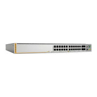
Allied Telesis AT-x530-28GPXm Installation Manual (128 pages)
Stackable Gigabit Layer 3+ Ethernet Switches AlliedWare Plus v5.4.8-2
Brand:
Allied Telesis
| Category:
Switch
| Size: 5.7 MB
Table of Contents
Table of Contents
5
Preface
11
Document Conventions
12
Contacting Allied Telesis
13
Chapter 1: Overview
15
Front and Rear Panels
16
Figure 1: Front Panels of the X530 Series Switches
16
Figure 2: Back Panels of the X530 Series Switches
17
Management Panel
18
Figure 3: Management Panel
18
Features
19
X530 Models
19
Twisted Pair Ports
19
Table 1: Basic Features
19
Power over Ethernet
20
SFP+ Transceiver Slots
20
Leds
20
Installation Options
21
Management Software and Interfaces
21
Management Methods
21
Twisted Pair Ports
22
Table 2: AT-X530-28Gtxm Switch Twisted Pair Port Specifications
22
Table 3: AT-X530-28Gpxm Switch Twisted Pair Port Specifications
22
Duplex Mode
23
Speed
23
Wiring Configuration
23
Cable Requirements
24
Maximum Distance
24
Table 4: Cable Requirements for Ports 1 - 24 at 100 Mbps or 1 Gbps
24
Figure 4: AT-X530-28Gtxm Twisted Pair Ports 1-24 Leds
25
Leds
25
Port Pinouts
25
Table 5: AT-X530-28Gtxm Twisted Pair Ports 1 - 24 LED Functions
25
Figure 5: AT-X530-28Gpxm Twisted Pair Ports 1-24 Leds
26
Table 6: AT-X530-28Gpxm Twisted Pair Ports 1 - 24 LED Functions
26
Power over Ethernet on the AT-X530-28Gpxm Switch
28
Poe Standards
28
Powered Device Classes
29
Power Budget
29
Port Prioritization
29
Table 7: IEEE Powered Device Classes
29
Wiring Implementation
30
SFP+ Transceiver Slots on the AT-X530-28Gtxm and AT-X530-28Gpxm Switches
31
SFP and SFP+ Transceivers
31
Leds
31
Figure 6: Link and Activity Leds for the 1 Gbps/10 Gbps SFP+ Slots
31
Table 8: Link and Activity Status Leds for the 1 Gbps and 10 Gbps Ports
32
Eco-Friendly Button
33
Vcstack Feature
34
Switch ID LED
35
Figure 7: Switch ID LED
35
Figure 8: Switch ID LED Description
36
USB Port
37
Console Port
38
Power Supply
39
Chapter 2: Virtual Chassis Stacking
41
Overview
42
Stacking Guidelines
43
10 Gbps Stack Trunks
44
Figure 9: Valid Stack Trunk Using Default Stacking Ports 27 and 28
45
Figure 10: Valid Stack Trunk Using Ports 25 to 28
46
Invalid Stack Trunks
47
Example 1
47
Example 2
47
Figure 11: Invalid Stack Trunk with an Intermediary Networking Device
47
Figure 12: Invalid Stack Trunk with One Port Used Per Switch
47
Example 3
48
Figure 13: Invalid Stack Trunk with Different Numbers of Links
48
Example 4
49
Figure 14: Invalid 10 Gbps Stack Trunk with both Fiber Optic and AT-SP10TW Direct Connect Cables
49
Master and Member Switches
50
Selection of the Master Switch
50
Switch ID Numbers
52
Optional Feature Licenses
53
Planning the Stack
54
Chapter 3: Beginning the Installation
55
Reviewing Safety Precautions
56
Choosing a Site for the Switch
60
Unpacking the AT-X530-28Gtxm or AT-X530-28Gpxm Switch
61
Figure 15: AT-X530-28Gtxm or AT-X530-28Gpxm Switch Shipping Box
61
Figure 16: Accessory Kit Items
62
Chapter 4: Installing the Switch on a Table
63
Figure 17: Parts of the Bumper Feet
63
Figure 18: Holes for Bumper Feet
64
Figure 19: Inserting the Rivet Housing into the Bumper Foot
64
Figure 20: Placing the Bumper Foot on a Base Corner Hole
65
Figure 21: Inserting the Rivet into the Bumper Foot
65
Chapter 5: Installing the Switch in an Equipment Rack
67
Installing AT-X530-28Gtxm or AT-X530-28Gpxm Switches in an Equipment Rack
68
Required Items
68
Switch Orientations in the Equipment Rack
68
Figure 22: Bracket Holes on the AT-X530-28Gtxm and AT-X530-28Gpxm Switches
68
Installing the Switch
69
Figure 23: Switch Orientations in an Equipment Rack
69
Figure 24: Example of Attaching the Brackets to the Switch
70
Figure 25: Installing the Switch in an Equipment Rack
71
Chapter 6: Installing the Switch on a Wall
73
Switch Orientations on a Wall
74
Figure 26: Positioning the AT-X530-28Gtxm Switch on the Wall
74
Figure 27: Positioning the AT-X530-28Gpxm Switch on the Wall
75
Installation Guidelines
76
Tools and Material
77
Plywood Base for a Wall with Wooden Studs
78
Figure 28: Installing the Plywood Base to the Wall
79
Figure 29: Installing the Switch on the Plywood Base
80
Installing a Plywood Base
81
Installing the Switch on a Plywood Base
82
Figure 30: Installing Two Brackets on the AT-X530-28Gtxm Switch
83
Figure 31: Installing Four Brackets on the AT-X530-28Gpxm Switch
84
Figure 32: Securing the AT-X530-28Gtxm Switch to the Plywood Base
85
Figure 33: Securing the AT-X530-28Gpxm Switch to the Plywood Base
86
Installing the Switch on a Concrete Wall
87
Figure 34: Marking the Locations of the Bracket Holes on a Concrete Wall
88
Figure 35: Installing the Switch on a Concrete Wall
89
Chapter 7: Powering on the Stack
91
Introduction
92
Installing the Power Cord Retaining Clips
93
Figure 36: Installing the Retaining Clip
93
Powering on the Switches Individually
94
Figure 37: Plugging in the AC Power Cord to the Switch
95
Figure 38: Plugging in the AC Power Cord to an AC Source
96
Powering on the Switches Simultaneously
98
Starting a Local Management Session
100
Figure 39: Connecting the Management Cable to the Console Port
100
Verifying the Stack
102
Adding Ports 25 and 26 to the Stack Trunk
103
Table 9: Adding Ports 25 and 26 to the Stack Trunk
103
Monitoring the Initialization Processes
105
Figure 40: Switch Initialization Messages
105
Figure 41: Switch Initialization Messages (Continued)
106
Figure 42: Switch Initialization Messages (Continued)
107
Chapter 8: Cabling the Networking Ports
109
Cabling Twisted Pair Ports
110
Guidelines to Handling SFP and SFP+ Transceivers
111
Installing SFP or SFP+ Transceivers in AT-X530-28Gtxm and AT-X530-28Gpxm Switches
112
Figure 43: Removing the Dust Plug from an SFP Slot
112
Figure 44: Installing an SFP Transceiver
113
Figure 45: Removing the Dust Cover from an SFP or SFP+ Transceiver
113
Figure 46: Positioning the SFP or SFP+ Handle in the Upright Position
114
Figure 47: Connecting a Fiber Optic Cable to an SFP or SFP+ Transceiver
114
Installing AT-SP10TW Direct Connect Twinax Cables in AT-X530-28Gtxm and AT-X530-28Gpxm Switches
115
Figure 48: Installing AT-SP10TW Cables
116
Chapter 9: Troubleshooting
117
Appendix A: Technical Specifications
121
Physical Specifications
122
Table 10: Product Dimensions
122
Table 11: Product Weights
122
Table 12: Ventilation Requirements
122
Environmental Specifications
123
Table 13: Environmental Specifications
123
Power Specifications
124
Table 14: Maximum Power Consumptions
124
Table 15: Input Voltages
124
Table 16: Heat Dissipation
124
Certifications
125
Table 17: Product Certifications
125
RJ-45 Twisted Pair Port Pinouts
126
Figure 49: RJ-45 Socket Pin Layout (Front View)
126
Table 18: Pin Signals for 100M/1G/2.5G/5G Base-T Connectors
126
RJ-45 Style Serial Console Port Pinouts
127
Table 19: RJ-45 Style Serial Console Port Pin Signals
127
USB Port
128
Table 20: USB Port Pin Signals
128
Advertisement
Advertisement
Related Products
Allied Telesis AT-x530-28GTXm
Allied Telesis AT-x530L-52GPX
Allied Telesis AT-x530L-52GTX
Allied Telesis AT-x530L-28GPX
Allied Telesis AT-x530L-28GTX
Allied Telesis AT-x510DP-52GTX
Allied Telesis AT-x510-52GTX
Allied Telesis AT-x510-28GSX-80
Allied Telesis AT-x550-18XSPQm
Allied Telesis AT-x510L-52GP
Allied Telesis Categories
Switch
Network Router
Media Converter
Network Hardware
Wireless Access Point
More Allied Telesis Manuals
Login
Sign In
OR
Sign in with Facebook
Sign in with Google
Upload manual
Upload from disk
Upload from URL