Agilent Technologies 8163B Manuals
Manuals and User Guides for Agilent Technologies 8163B. We have 5 Agilent Technologies 8163B manuals available for free PDF download: Manual, User Manual, Programming Manual

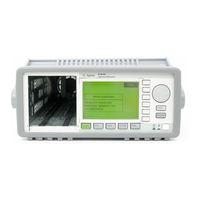
Agilent Technologies 8163B Manual (466 pages)
Lightwave Multimeter
Brand: Agilent Technologies
|
Category: Measuring Instruments
|
Size: 11.13 MB
Table of Contents
-
General26
-
Password40
-
Laser Sources109
-
Tunable Lasers119
-
Wavelength Range130
-
Auto Cal off156
-
SBS Suppression161
-
Setup172
-
Reference190
-
Patchcord191
-
Your Test Setup212
-
Applications229
-
How to Zoom in233
-
How to Zoom out234
Advertisement
Agilent Technologies 8163B User Manual (446 pages)
Lightwave Multimeter,Lightwave Measurement System,Lightwave Multichannel System
Brand: Agilent Technologies
|
Category: Measuring Instruments
|
Size: 8.58 MB
Table of Contents
-
-
General3
-
-
-
-
Password39
-
-
-
-
-
-
-
-
Laser Sources
103 -
-
Tunable Lasers
113 -
-
-
-
Applications
213-
-
How to Zoom in216
-
How to Zoom out217
-
-
-
The Pmax Curve260
-
-
Configuration263
-
User Interface264
-

Agilent Technologies 8163B Manual (466 pages)
Lightwave Multimeter & Lightwave Multichannel System
Brand: Agilent Technologies
|
Category: Multimeter
|
Size: 9.87 MB
Table of Contents
-
-
-
-
-
-
Laser Sources
109 -
Tunable Lasers
119 -
-
-
-
Your Test Setup212
-
-
Applications
229-
The Pmax Curve278
Advertisement

Agilent Technologies 8163B Programming Manual (274 pages)
Lightwave Multimeter; Lightwave Measurement System; Lightwave Multichannel System
Brand: Agilent Technologies
|
Category: Measuring Instruments
|
Size: 1.71 MB
Table of Contents
-
-
Annotations37
-
Table85
-
-
Signal Routing169
-
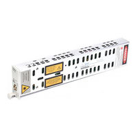
Agilent Technologies 8163B User Manual (61 pages)
DFB Laser Source Module
Brand: Agilent Technologies
|
Category: Control Unit
|
Size: 0.44 MB
Table of Contents
-
Accessories15
-
Test Record18
-
Test Failure18
-
Test Records21