Sign In
Upload
Manuals
Brands
ABB Manuals
Controller
ACS800-U1
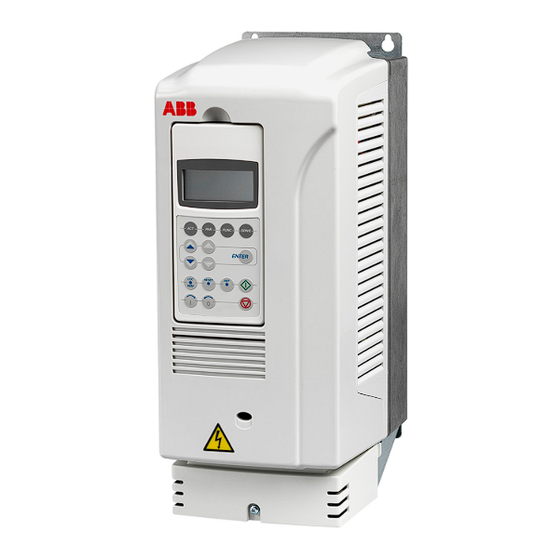
User Manuals: ABB ACS800-U1 Variable Frequency Drive
Manuals and User Guides for ABB ACS800-U1 Variable Frequency Drive. We have
5
ABB ACS800-U1 Variable Frequency Drive manuals available for free PDF download: Hardware Manual, Application Manual
ABB ACS800-U1 Hardware Manual (180 pages)
Brand:
ABB
| Category:
DC Drives
| Size: 20.75 MB
Table of Contents
Table of Contents
5
1 Safety Instructions
11
What this Chapter Contains
11
Use of Warnings and Notes
11
Installation and Maintenance Work
12
Grounding
13
Mechanical Installation and Maintenance
14
Printed Circuit Boards
14
Fiber-Optic Cables
14
Operation
15
Permanent Magnet Motor
16
Installation and Maintenance Work
16
Start-Up and Operation
16
2 Introduction to this Manual
17
What this Chapter Contains
17
Intended Audience
17
Categorization by Frame Size
17
Categorization According to the + Code
18
Contents
18
Installation and Commissioning Flowchart
19
Terms and Abbreviations
21
3 Operation Principle and Hardware Description
23
What this Chapter Contains
23
Product Overview
24
Type Code
25
Main Circuit and Control
26
Diagram
26
Operation
26
Printed Circuit Boards
27
Motor Control
27
4 Mechanical Installation
29
What this Chapter Contains
29
Unpacking the Unit
29
Example 1
30
Example 2
31
Checking the Delivery
32
Before Installation
32
Requirements for the Installation Site
32
Wall
32
Floor
32
Free Space Around the Unit
33
Mounting the Drive on the Wall
34
Units Without Vibration Dampers
34
IP55 (UL Type 12) Marine Applications (+C132) of Frame Sizes R4 to R6
34
Units with Vibration Dampers (+C131)
34
UL 12 Units
34
Cabinet Installation
35
Preventing Cooling Air Recirculation
35
Unit above Another
35
5 Planning the Electrical Installation
37
What this Chapter Contains
37
Motor Selection and Compatibility
38
Protecting the Motor Insulation and Bearings
39
Requirements Table
40
Permanent Magnet Motor
44
Supply Connection
45
Disconnecting Device
45
Fuses
45
Main Contactor
45
Thermal Overload and Short-Circuit Protection
46
Thermal Overload Protection of the Drive and the Input and Motor Cables
46
Thermal Overload Protection of the Motor
46
Sensors
46
Protecting the Motor and Motor Cable in Short Circuits
47
Protection against Short Circuits in the Drive or Supply Cable
48
Fuses
48
Circuit Breaker
48
Ground Fault Protection
49
Prevention of Unexpected Start-Up (Option +Q950)
49
Safe Torque off (Option +Q967)
50
Safe Torque off Circuit Diagram
51
Selecting the Power Cables
52
Alternative Power Cable Types
53
Motor Cable Shield
54
Additional US Requirements
54
Conduit
54
Armored Cable / Shielded Power Cable
54
Power Factor Compensation Capacitors
55
Equipment Connected to the Motor Cable
55
Installation of Safety Switches, Contactors, Connection Boxes, Etc
55
Bypass Connection
55
Using a Contactor between the Drive and the Motor
56
Tive Loads
57
Selecting the Control Cables
58
Relay Cable
58
Control Panel Cable
58
Connection of a Motor Temperature Sensor to the Drive I/O
59
Installation Sites above 2000 Metres (6562 Feet)
59
Routing the Cables
60
Control Cable Ducts
60
6 Electrical Installation
61
What this Chapter Contains
61
Checking the Insulation of the Installation
61
Drive
61
Supply Cable
61
Motor and Motor Cable
62
IT (Ungrounded) Systems
62
Connecting the Power Cables
63
Diagram
63
Conductor Stripping Lengths
64
Allowed Wire Sizes, Tightening Torques
64
Wall-Mounted Units (European Version)
64
Power Cable Installation Procedure
64
Wall-Mounted Units (US Version)
68
Warning Sticker
69
Cabinet Installation (IP21, UL Type 1)
70
Frame Size R5
70
Frame Size R6
71
Connecting the Control Cables
72
Terminals
72
360-Degree Grounding
74
Connecting the Shield Wires
74
Cabling of I/O and Fieldbus Modules
75
Pulse Encoder Module Cabling
75
Attaching the Control Cables and Covers
76
Installation of Option Modules and PC
76
Fiber-Optic Link
76
7 Installation of the AGPS Board (Prevention of Unexpected Start-Up, +Q950)
77
What this Chapter Contains
77
Prevention of Unexpected Start-Up (+Q950)
77
Installation of the AGPS Board
77
Circuit Diagram
80
Start-Up and Validation
81
Use
81
Maintenance
81
Dimensional Drawing
81
8 Installation of the ASTO Board (Safe Torque Off, +Q967)
83
What this Chapter Contains
83
Safe Torque off (+Q967)
83
Installation of the ASTO Board
83
Circuit Diagram
86
Start-Up and Validation
86
Dimensional Drawing
86
9 Motor Control and I/O Board (RMIO)
87
What this Chapter Contains
87
Note on Terminal Labelling
87
Note on External Power Supply
87
Parameter Settings
88
External Control Connections (Non-US)
89
External Control Connections (US)
90
RMIO Board Specifications
91
Analogue Inputs
91
Constant Voltage Output
91
Auxiliary Power Output
91
Analogue Outputs
91
Digital Inputs
91
Relay Outputs
92
DDCS Fibre Optic Link
92
DC Power Input
92
10 Installation Checklist
95
What this Chapter Contains
95
Checklist
95
11 Start-Up and Use
97
What this Chapter Contains
97
Start-Up Procedure
97
Control Panel
98
Removing the Control Panel
98
12 Maintenance
99
What this Chapter Contains
99
Safety
99
Maintenance Intervals
99
Heatsink
100
Fan
100
Fan Replacement (R2, R3)
100
Fan Replacement (R4)
101
Fan Replacement (R5)
102
Fan Replacement (R6)
103
Additional Fan
104
Replacement (R2, R3)
104
Replacement (R4, R5)
104
Replacement (R6)
104
Capacitors
105
Reforming
105
Leds
105
13 Technical Data
107
What this Chapter Contains
107
IEC Data
108
Ratings
108
Symbols
110
Sizing
110
Derating
111
Temperature Derating
111
Altitude Derating
111
Fuses
111
Frame Sizes R2 to R4
111
Frame Sizes R5 and R6
113
Calculation Example
113
Fuse Tables for Frame Sizes R5 and R6
114
Standard Gg Fuses
114
Ultrarapid (Ar) Fuses
116
Quick Guide for Selecting between Gg and Ar Fuses
117
Cable Types
119
Cable Entries
120
Dimensions, Weights and Noise
120
Package Dimensions and Weights
120
NEMA Data
121
Ratings
121
Symbols
122
Sizing
122
Derating
122
Fuses
123
Cable Types
124
Cable Entries
125
Dimensions, Weights and Noise
125
Package Dimensions and Weights
125
Input Power Connection
126
Motor Connection
126
Efficiency
126
Energy Efficiency Data (Ecodesign)
127
Cooling
127
Degree of Protection
127
AGPS-11C (Option +Q950)
127
ASTO-11C (Option +Q967)
127
Ambient Conditions
128
Materials
129
Applicable Standards
129
CE Marking
130
Compliance with the European Low Voltage Directive
130
Compliance with the European EMC Directive
130
Compliance with the European Machinery Directive
130
Compliance with en 61800-3:2004
130
Definitions
130
First Environment (Drive of Category C2)
131
Second Environment (Drive of Category C3)
131
Second Environment (Drive of Category C4)
132
C-Tick" Marking
132
Marine Type Approvals
132
UL/CSA Markings
133
UL Checklist
133
Disclaimer
133
Cybersecurity Disclaimer
133
Advertisement
ABB ACS800-U1 Hardware Manual (174 pages)
Brand:
ABB
| Category:
DC Drives
| Size: 5.8 MB
Table of Contents
List of Related Manuals
2
Safety Instructions
5
What this Chapter Contains
5
Use of Warnings and Notes
5
Installation and Maintenance Work
6
Grounding
7
Mechanical Installation and Maintenance
8
Printed Circuit Boards
8
Fibre Optic Cables
8
Operation
9
Permanent Magnet Motor
10
Installation and Maintenance Work
10
Start-Up and Operation
10
Table of Contents
11
Table of Contents
19
Introduction to this Manual
19
What this Chapter Contains
19
Intended Audience
19
Categorization According to the Frame Size
19
Categorization According to the + Code
19
Contents
20
Installation and Commissioning Flowchart
21
Terms and Abbreviations
22
Operation Principle and Hardware Description
25
What this Chapter Contains
25
Product Overview
25
Type Code
26
Main Circuit and Control
27
Diagram
27
Operation
27
Printed Circuit Boards
28
Motor Control
28
Mechanical Installation
29
What this Chapter Contains
29
Unpacking the Unit
29
Example 1
30
Example 2
31
Checking the Delivery
32
Before Installation
32
Requirements for the Installation Site
32
Wall
32
Floor
32
Free Space Around the Unit
33
Mounting the Drive on the Wall
34
Units Without Vibration Dampers
34
IP55 (UL Type 12) Marine Applications (+C132) of Frame Sizes R4 to R6
34
Units with Vibration Dampers (+C131)
34
UL 12 Units
34
Cabinet Installation
35
Preventing Cooling Air Recirculation
35
Unit above Another
36
Planning the Electrical Installation
37
What this Chapter Contains
37
Motor Selection and Compatibility
37
Protecting the Motor Insulation and Bearings
38
Requirements Table
39
Permanent Magnet Motor
43
Supply Connection
44
Disconnecting Device
44
Fuses
44
Main Contactor
44
Thermal Overload and Short-Circuit Protection
45
Thermal Overload Protection of the Drive and the Input and Motor Cables
45
Thermal Overload Protection of the Motor
45
Protection against Short-Circuit in the Motor Cable
45
Protection against Short-Circuit Inside the Drive or in the Supply Cable
46
Fuses
46
Circuit Breaker
46
Ground Fault Protection
47
Prevention of Unexpected Start-Up (Option +Q950)
48
Safe Torque off (Option +Q967)
49
Safe Torque off Circuit Diagram
50
Selecting the Power Cables
51
General Rules
51
Alternative Power Cable Types
52
Motor Cable Shield
53
Additional US Requirements
53
Conduit
53
Armored Cable / Shielded Power Cable
53
Power Factor Compensation Capacitors
54
Equipment Connected to the Motor Cable
54
Installation of Safety Switches, Contactors, Connection Boxes, Etc
54
Bypass Connection
54
Using a Contactor between the Drive and the Motor
55
Protecting the Relay Output Contacts and Attenuating Disturbances in Case of Inductive Loads
56
Selecting the Control Cables
57
Relay Cable
57
Control Panel Cable
57
Connection of a Motor Temperature Sensor to the Drive I/O
58
Installation Sites above 2000 Metres (6562 Feet)
58
Routing the Cables
58
Control Cable Ducts
59
Electrical Installation
61
What this Chapter Contains
61
Checking the Insulation of the Installation
61
Drive
61
Supply Cable
61
Motor and Motor Cable
62
IT (Ungrounded) Systems
62
Connecting the Power Cables
63
Diagram
63
Conductor Stripping Lengths
64
Allowed Wire Sizes, Tightening Torques
64
Wall Installed Units (European Version)
64
Power Cable Installation Procedure
64
Wall Installed Units (US Version)
68
Warning Sticker
69
Cabinet Installation (IP21, UL Type 1)
70
Frame Size R5
70
Frame Size R6
71
Connecting the Control Cables
72
Terminals
72
Degrees Grounding
74
Connecting the Shield Wires
74
Cabling of I/O and Fieldbus Modules
75
Pulse Encoder Module Cabling
75
Fastening the Control Cables and Covers
76
Installation of Option Modules and PC
76
Fibre Optic Link
76
Installation of the AGPS Board (Prevention of Unexpected Start-Up, +Q950)
77
What this Chapter Contains
77
Prevention of Unexpected Start-Up (+Q950)
77
Installation of the AGPS Board
77
Circuit Diagram
80
Start-Up and Validation
81
Use
81
Maintenance
81
Dimensional Drawing
81
Installation of the ASTO Board (Safe Torque Off, +Q967)
83
What this Chapter Contains
83
Safe Torque off (+Q967)
83
Installation of the ASTO Board
83
Circuit Diagram
86
Start-Up and Validation
86
Dimensional Drawing
86
Motor Control and I/O Board (RMIO)
87
What this Chapter Contains
87
Note on Terminal Labelling
87
Note on External Power Supply
87
Parameter Settings
87
External Control Connections (Non-US)
88
External Control Connections (US)
89
RMIO Board Specifications
90
Analogue Inputs
90
Constant Voltage Output
90
Auxiliary Power Output
90
Analogue Outputs
90
Digital Inputs
90
Relay Outputs
91
DDCS Fibre Optic Link
91
24 V DC Power Input
91
Installation Checklist
93
What this Chapter Contains
93
Checklist
93
Start-Up and Use
95
What this Chapter Contains
95
Startup Procedure
95
Control Panel
95
Removing the Control Panel
95
Maintenance
97
What this Chapter Contains
97
Safety
97
Maintenance Intervals
97
Heatsink
98
Fan
98
Fan Replacement (R2, R3)
98
Fan Replacement (R4)
99
Fan Replacement (R5)
100
Fan Replacement (R6)
101
Additional Fan
102
Replacement (R2, R3)
102
Replacement (R4, R5)
102
Replacement (R6)
102
Capacitors
103
Reforming
103
Leds
103
Technical Data
105
What this Chapter Contains
105
IEC Data
105
Ratings
105
Symbols
107
Sizing
107
Derating
108
Temperature Derating
108
Altitude Derating
108
Fuses
108
Frame Sizes R2 to R4
108
Frame Sizes R5 and R6
110
Calculation Example
110
Fuse Tables for Frame Sizes R5 and R6
111
Standard Gg Fuses
111
Ultrarapid (Ar) Fuses
113
Quick Guide for Selecting between Gg and Ar Fuses
114
Cable Types
116
Cable Entries
117
Dimensions, Weights and Noise
117
Package Dimensions and Weights
117
NEMA Data
118
Ratings
118
Symbols
119
Sizing
119
Derating
119
Fuses
120
Cable Types
121
Cable Entries
122
Dimensions, Weights and Noise
122
Package Dimensions and Weights
122
Input Power Connection
123
Motor Connection
123
Efficiency
123
Cooling
124
Degree of Protection
124
AGPS-11C (Option +Q950)
124
ASTO-11C (Option +Q967)
124
Ambient Conditions
125
Materials
126
Applicable Standards
126
CE Marking
127
Compliance with the European Low Voltage Directive
127
Compliance with the European EMC Directive
127
Compliance with the European Machinery Directive
127
Compliance with en 61800-3:2004
127
Definitions
127
First Environment (Drive of Category C2)
128
Second Environment (Drive of Category C3)
128
Second Environment (Drive of Category C4)
129
C-Tick" Marking
129
Marine Type Approvals
129
UL/CSA Markings
130
UL Checklist
130
Disclaimer
130
ABB ACS800-U1 Hardware Manual (154 pages)
Brand:
ABB
| Category:
Controller
| Size: 8.01 MB
Table of Contents
ACS800 Single Drive Manuals
2
Safety Instructions
5
What this Chapter Contains
5
Use of Warnings and Notes
5
Installation and Maintenance Work
6
Grounding
7
Mechanical Installation and Maintenance
8
Printed Circuit Boards
9
Fibre Optic Cables
9
Operation
10
Permanent Magnet Motor
11
Installation and Maintenance Work
11
Start-Up and Operation
11
Table of Contents
13
Table of Contents
19
About this Manual
19
What this Chapter Contains
19
Intended Audience
19
Common Chapters for Several Products
19
Categorization According to the Frame Size
19
Categorization According to the + Code
19
Contents
20
Installation and Commissioning Flowchart
21
Product and Service Inquiries
22
Product Training
22
Providing Feedback on ABB Drives Manuals
22
The ACS800-01/U1
23
What this Chapter Contains
23
Type Code
24
Main Circuit and Control
25
Diagram
25
Operation
25
Printed Circuit Boards
26
Motor Control
26
Mechanical Installation
27
Unpacking the Unit
27
Delivery Check
28
Before Installation
28
Requirements for the Installation Site
28
Wall
28
Floor
28
Free Space Around the Unit
29
Mounting the Drive on the Wall
30
Units Without Vibration Dampers
30
IP 55 (UL Type 12) Marine Applications (+C132) of Frame Sizes R4 to R6
30
Units with Vibration Dampers (+C131)
30
UL 12 Units
30
Cabinet Installation
31
Preventing Cooling Air Recirculation
31
Unit above Another
32
Planning the Electrical Installation
33
What this Chapter Contains
33
Motor Selection and Compatibility
33
Protecting the Motor Insulation and Bearings
34
Requirements Table
35
Permanent Magnet Synchronous Motor
38
Supply Connection
39
Disconnecting Device (Disconnecting Means)
39
Fuses
39
Main Contactor
39
Thermal Overload and Short-Circuit Protection
40
Thermal Overload Protection of the Drive and the Input and Motor Cables
40
Thermal Overload Protection of the Motor
40
Protection against Short-Circuit in the Motor Cable
40
Protection against Short-Circuit Inside the Drive or in the Supply Cable
41
Fuses
41
Circuit Breaker
41
Ground Fault Protection
42
Prevention of Unexpected Start
42
Selecting the Power Cables
43
General Rules
43
Alternative Power Cable Types
44
Motor Cable Shield
44
Additional US Requirements
45
Conduit
45
Armored Cable / Shielded Power Cable
45
Power Factor Compensation Capacitors
45
Equipment Connected to the Motor Cable
46
Installation of Safety Switches, Contactors, Connection Boxes, Etc
46
Bypass Connection
46
Before Opening a Contactor (DTC Control Mode Selected)
46
Protecting the Relay Output Contacts and Attenuating Disturbances in Case of Inductive Loads
47
Selecting the Control Cables
48
Relay Cable
48
Control Panel Cable
48
Connection of a Motor Temperature Sensor to the Drive I/O
49
Installation Sites above 2000 Metres (6562 Feet)
49
Routing the Cables
49
Control Cable Ducts
50
Electrical Installation
51
What this Chapter Contains
51
Checking the Insulation of the Assembly
52
Drive
52
Input Cable
52
Motor and Motor Cable
52
IT (Ungrounded) Systems
52
Connecting the Power Cables
53
Diagram
53
Conductor Stripping Lengths
54
Allowed Wire Sizes, Tightening Torques
54
Wall Installed Units (European Version)
54
Power Cable Installation Procedure
54
Wall Installed Units (US Version)
58
Warning Sticker
59
Cabinet Installation (IP 21, UL Type 1)
59
Frame Size R5
60
Frame Size R6
61
Connecting the Control Cables
62
Terminals
62
Degrees Grounding
64
When the Outer Surface of the Shield Is Covered with Non-Conductive Material
64
Connecting the Shield Wires
64
Cabling of I/O and Fieldbus Modules
65
Pulse Encoder Module Cabling
65
Fastening the Control Cables and Covers
66
Installation of Optional Modules and PC
66
Fibre Optic Link
66
Installation of AGPS Board (Prevention of Unexpected Start, +Q950)
67
What this Chapter Contains
67
Prevention of Unexpected Start (+Q950)
67
Installation of the AGPS Board
67
Circuit Diagram
69
Dimensional Drawing
70
AGPS-11C Board Specifications
71
Motor Control and I/O Board (RMIO)
73
What this Chapter Contains
73
Note on Terminal Labelling
73
Note on External Power Supply
73
Parameter Settings
73
External Control Connections (Non-US)
74
External Control Connections (US)
75
RMIO Board Specifications
76
Analogue Inputs
76
Constant Voltage Output
76
Auxiliary Power Output
76
Analogue Outputs
76
Digital Inputs
76
Relay Outputs
77
DDCS Fibre Optic Link
77
24 V DC Power Input
77
Installation Checklist
79
Checklist
79
Maintenance
81
What this Chapter Contains
81
Safety
81
Maintenance Intervals
81
Heatsink
82
Fan
82
Fan Replacement (R2, R3)
82
Fan Replacement (R4)
83
Fan Replacement (R5)
84
Fan Replacement (R6)
85
Additional Fan
85
Replacement (R2, R3)
85
Replacement (R4, R5)
86
Replacement (R6)
86
Capacitors
86
Reforming
86
Leds
87
Technical Data
89
What this Chapter Contains
89
IEC Data
89
Ratings
89
Symbols
91
Sizing
91
Derating
92
Temperature Derating
92
Altitude Derating
92
Fuses
92
Frame Sizes R2 to R4
92
Frame Sizes R5 and R6
94
Calculation Example
94
Fuse Tables for Frame Sizes R5 and R6
96
Standard Gg Fuses
96
Ultrarapid (Ar) Fuses
97
Quick Guide for Selecting between Gg and Ar Fuses
99
Cable Types
100
Cable Entries
101
Dimensions, Weights and Noise
101
NEMA Data
102
Ratings
102
Symbols
103
Sizing
103
Derating
103
Fuses
104
Cable Types
105
Cable Entries
106
Dimensions, Weights and Noise
106
Input Power Connection
107
Motor Connection
107
Efficiency
107
Cooling
108
Degrees of Protection
108
Ambient Conditions
108
Materials
109
Applicable Standards
109
CE Marking
110
Definitions
110
Compliance with the EMC Directive
110
Compliance with the en 61800-3 (2004)
110
First Environment (Drive of Category C2)
110
Second Environment (Drive of Category C3)
111
Second Environment (Drive of Category C4)
111
Machinery Directive
111
C-Tick" Marking
112
Definitions
112
Compliance with IEC 61800-3
112
First Environment (Drive of Category C2)
112
Second Environment (Drive of Category C3)
113
Second Environment (Drive of Category C4)
113
Marine Type Approvals
113
UL/CSA Markings
114
US Patents
114
Equipment Warranty and Liability
114
Frame Size R2 (IP 21, UL Type 1)
118
Frame Size R2 (IP 55, UL Type 12)
119
Frame Size R3 (IP 21, UL Type 1)
120
Frame Size R3 (IP 55, UL Type 12)
121
Frame Size R4 (IP 21, UL Type 1)
122
Frame Size R4 (IP 55, UL Type 12)
123
Frame Size R5 (IP 21, UL Type 1)
124
Frame Size R5 (IP 55, UL Type 12)
125
Frame Size R6 (IP 21, UL Type 1)
126
Frame Size R6 (IP 21, UL Type 1), -205-3 and -255-5 Units
127
Frame Size R6 (IP 55, UL Type 12)
128
Dimensional Drawings (USA)
130
Frame Size R2 (UL Type 1, IP 21)
131
Frame Size R2 (UL Type 12, IP 55)
132
Frame Size R3 (UL Type 1, IP 21)
133
Frame Size R3 (UL Type 12, IP 55)
134
Frame Size R4 (UL Type 1, IP 21)
135
Frame Size R4 (UL Type 12, IP 55)
136
Frame Size R5 (UL Type 1, IP 21)
137
Frame Size R5 (UL Type 12, IP 55)
138
Frame Size R6 (UL Type 1, IP 21)
139
Frame Size R6 (UL Type 1, IP 21) -0205-3 and -0255-5 Units
140
Frame Size R6 (UL Type 12, IP 55)
141
Advertisement
ABB ACS800-U1 Hardware Manual (132 pages)
Drives (0.55 to 110 kW). Drives (0.75 to 150 HP)
Brand:
ABB
| Category:
Controller
| Size: 8.73 MB
Table of Contents
ACS800 Single Drive Manuals
2
Safety Instructions
5
What this Chapter Contains
5
To Which Products this Chapter Applies
5
Use of Warnings and Notes
5
Installation and Maintenance Work
6
Grounding
7
Fibre Optic Cables
8
Mechanical Installation
8
Operation
9
Permanent Magnet Motor
10
Installation and Maintenance Work
10
Operation
10
Table of Contents
11
About this Manual
17
What this Chapter Contains
17
Intended Audience
17
Common Chapters for Several Products
17
Categorization According to the Frame Size
17
Categorization According to the + Code
17
Contents
18
Installation and Commissioning Flowchart
19
Inquiries
20
The ACS800-01/U1
21
What this Chapter Contains
21
Type Code
22
Main Circuit and Control
23
Diagram
23
Operation
23
Printed Circuit Boards
24
Motor Control
24
Mechanical Installation
25
Unpacking the Unit
25
Delivery Check
26
Before Installation
26
Requirements for the Installation Site
26
Wall
26
Floor
26
Free Space Around the Unit
27
Mounting the Drive on the Wall
28
Units Without Vibration Dampers
28
IP 55 (UL Type 12) Marine Applications (+C132) of Frame Sizes R4 to R6
28
Units with Vibration Dampers (+C131)
28
UL 12 Units
28
Cabinet Installation
29
Preventing Cooling Air Recirculation
29
Unit above Another
30
Planning the Electrical Installation
31
What this Chapter Contains
31
To Which Products this Chapter Applies
31
Motor Selection and Compatibility
31
Protecting the Motor Insulation and Bearings
32
Requirements Table
33
Permanent Magnet Synchronous Motor
35
Supply Connection
35
Disconnecting Device (Disconnecting Means)
35
Acs800-04, Acs800-U4
35
ACS800-U2 with Enclosure Extension, ACS800-07 and ACS800-U7
35
Fuses
35
Thermal Overload and Short-Circuit Protection
36
Mains Cable (AC Line Cable) Short-Circuit Protection
36
ACS800-01/U1, ACS800-02/U2 Without Enclosure Extension and ACS800-04/U4
36
Drive AC Fuses (ACS800-07/U7, and ACS800-02/U2 with Enclosure Extension)
36
Operating Time of the Fuses
36
Circuit Breakers
37
Ground Fault Protection
37
Emergency Stop Devices
37
ACS800-02/U2 with Enclosure Extension and ACS800-07/U7
37
Restarting after an Emergency Stop
37
Prevention of Unexpected Start
38
Selecting the Power Cables
39
General Rules
39
Alternative Power Cable Types
40
Motor Cable Shield
40
Additional US Requirements
41
Conduit
41
Armored Cable / Shielded Power Cable
41
Power Factor Compensation Capacitors
41
Equipment Connected to the Motor Cable
42
Installation of Safety Switches, Contactors, Connection Boxes, Etc
42
Bypass Connection
42
Before Opening a Contactor (DTC Control Mode Selected)
42
Protecting the Relay Output Contacts and Attenuating Disturbances in Case of Inductive Loads
43
Selecting the Control Cables
44
Relay Cable
44
Control Panel Cable
44
Connection of a Motor Temperature Sensor to the Drive I/O
45
Routing the Cables
45
Control Cable Ducts
46
Electrical Installation
47
What this Chapter Contains
47
Checking the Insulation of the Assembly
48
IT (Ungrounded) Systems
48
Connecting the Power Cables
49
Diagram
49
Conductor Stripping Lengths
50
Allowed Wire Sizes, Tightening Torques
50
Wall Installed Units (European Version)
50
Power Cable Installation Procedure
50
Wall Installed Units (US Version)
54
Warning Sticker
55
Cabinet Installation (IP 21, UL Type 1)
55
Frame Size R5
56
Frame Size R6
57
Connecting the Control Cables
58
Terminals
58
Degrees Grounding
60
When the Outer Surface of the Shield Is Covered with Non-Conductive Material
60
Connecting the Shield Wires
60
Cabling of I/O and Fieldbus Modules
61
Pulse Encoder Module Cabling
61
Fastening the Control Cables and Covers
62
Installation of Optional Modules and PC
62
Fibre Optic Link
62
External +24 V Power Supply for the RMIO Board
62
Motor Control and I/O Board (RMIO)
63
What this Chapter Contains
63
To Which Products this Chapter Applies
63
Note for the ACS800-02 with Enclosure Extension and the ACS800-07
63
Note on External Power Supply
63
External Control Connections (Non-US)
64
External Control Connections (US)
65
RMIO Board Specifications
66
Analogue Inputs
66
Constant Voltage Output
66
Auxiliary Power Output
66
Analogue Outputs
66
Digital Inputs
66
Relay Outputs
67
DDCS Fibre Optic Link
67
24 VDC Power Input
67
Installation Checklist
69
Checklist
69
Maintenance
71
What this Chapter Contains
71
Safety
71
Maintenance Intervals
71
Heatsink
72
Fan
72
Fan Replacement (R2, R3)
72
Fan Replacement (R4)
73
Fan Replacement (R5)
74
Fan Replacement (R6)
75
Additional Fan
75
Replacement (R2, R3)
75
Replacement (R4, R5)
75
Replacement (R6)
76
Capacitors
76
Reforming
76
Leds
76
Technical Data
77
What this Chapter Contains
77
IEC Ratings
77
Symbols
78
Sizing
79
Derating
79
Temperature Derating
79
Altitude Derating
79
Mains Cable Fuses
80
Cable Types
82
Cable Entries
82
Dimensions, Weights and Noise
83
Input Power Connection
83
Motor Connection
83
Cooling
84
Degrees of Protection
84
Efficiency
84
Ambient Conditions
85
Materials
86
Applicable Standards
86
CE Marking
87
Definitions
87
Compliance with the EMC Directive
87
First Environment (Restricted Distribution)
87
Second Environment
88
Machinery Directive
88
C-Tick" Marking
89
Definitions
89
Compliance with IEC 61800-3
89
First Environment (Restricted Distribution)
89
Second Environment
90
Marine Type Approvals
90
Equipment Warranty and Liability
90
ABB ACS800-U1 Application Manual (46 pages)
INDUSTRIAL DRIVES, Safe torque off function (+Q967)
Brand:
ABB
| Category:
DC Drives
| Size: 7.57 MB
Table of Contents
Table of Contents
5
1 Introduction to the Manual
7
Contents of this Chapter
7
Applicability
7
Safety Instructions
7
Target Audience
8
Contents
8
Abbreviations
9
2 Option Description
11
Contents of this Chapter
11
Description
11
Operation Principle
12
STO Status Indications
13
STO Function Activation and Indication Response Times
14
Module Response Times Only
14
Response Times with Typical Safety Relay
14
3 Installation
15
Contents of this Chapter
15
Supply Voltage
15
Connections
15
STO Input
15
Activation Switch
16
Cable Types and Lengths
16
Cable between STO Activation Switch and Drive/Inverter Module or ASTO Board
16
Cable between ASTO Board and Drive/Inverter Module
16
Example Wiring Diagrams
17
STO Connections Without Safety Relays
17
Connecting the STO Activation Switch
17
Frame Sizes R2 to R6
18
Frame Sizes R7 and R8
18
Frame Sizes R2I to R4I
19
Frame Size R5I
19
Frame Size R7I
20
Frame Size R8I
20
Liquid-Cooled Modules of Frame Sizes R7I and R8I
21
STO Connections with Safety Relays
22
Frame Sizes R2 to R6
22
Frame Sizes R7 and R8
23
Frame Sizes R2I to R4I
24
Frame Size R5I
25
Frame Size R7I
26
Frame Size R8I
27
Connecting Several Drive/Inverter Modules or Inverter Units to One Safety Relay
28
4 Start-Up and Use
29
Contents of this Chapter
29
Start-Up and Acceptance Test
29
Competence
29
Acceptance Test Reports
30
Acceptance Test Procedure
30
Use
31
5 Maintenance and Fault Tracing
33
Contents of this Chapter
33
Maintenance
33
Proof Test Interval
33
Competence
34
Fault Tracing
34
Warning Messages Generated by the Drive
34
Fault Messages Generated by the Drive
34
Advertisement
Related Products
ABB ACS800-U11-0011-2
ABB ACS800-U11-0016-2
ABB ACS800-U11-0020-2
ABB ACS800-U11-0025-2
ABB ACS800-U11-0030-2
ABB ACS800-U11-0040-2
ABB ACS800-U11-0050-2
ABB ACS800-U11-0060-2
ABB ACS800-U11-0020-5
ABB ACS800-U11-0025-5
ABB Categories
Industrial Equipment
Controller
Measuring Instruments
Battery Charger
DC Drives
More ABB Manuals
Login
Sign In
OR
Sign in with Facebook
Sign in with Google
Upload manual
Upload from disk
Upload from URL