ABB ACS800-U1 Hardware Manual
Hide thumbs
Also See for ACS800-U1:
- Hardware manual (174 pages) ,
- Application manual (46 pages) ,
- Hardware manual (132 pages)

Related Manuals for ABB ACS800-U1


Summary of Contents for ABB ACS800-U1
- Page 1 — ABB INDUSTRIAL DRIVES ACS800-01 drives (0.55 to 200 kW) ACS800-U1 drives (0.75 to 200 hp) Hardware manual...
- Page 2 Internet on the inside of the back cover. For manuals not available in the Document library, contact your local ABB representative. The code below opens an online listing of the manuals applicable to the product: ACS800-01/U1 manuals...
- Page 3 ACS800-01 (0.55 to 200 kW) ACS800-U1 (0.75 to 200 hp) Hardware manual Table of contents 1. Safety instructions 4. Mechanical installation 6. Electrical installation 11. Start-up and use 3AFE64382101 Rev L EFFECTIVE: 2023-12-01 2023 ABB. All Rights Reserved. ...
-
Page 5: Table Of Contents
Table of contents 1. Safety instructions What this chapter contains ........... . 9 Use of warnings and notes . - Page 6 IP55 (UL type 12) marine applications (+C132) of frame sizes R4 to R6 ..32 Units with vibration dampers (+C131) ........32 UL 12 units .
- Page 7 6. Electrical installation What this chapter contains ........... 59 Checking the insulation of the installation .
- Page 8 Parameter settings ............86 External control connections (non-US) .
- Page 9 Fuses ..............109 Frame sizes R2 to R4 .
- Page 10 Frame size R3 (IP55, UL type 12) ..........137 Frame size R4 (IP21, UL type 1) .
-
Page 11: Safety Instructions
Safety instructions 9 Safety instructions What this chapter contains This chapter contains the safety instructions that you must obey when you install, operate and service the drive. If you ignore them, physical injury or death may occur, or damage may occur to the drive, motor or driven equipment. Read the safety instructions before you do work on the unit. -
Page 12: Installation And Maintenance Work
10 Safety instructions Installation and maintenance work These warnings are intended for all person that do work on the drive, motor cable or motor. WARNING! If you ignore these safety instructions, physical injury or death, or damage to the equipment can occur: •... -
Page 13: Grounding
Safety instructions 11 • At installation sites that are above 2000 m (6562 ft), the terminals of the RMIO board and option modules attached to the board do not fulfill the Protective Extra Low Voltage (PELV) requirements in EN 50178. Grounding ... -
Page 14: Mechanical Installation And Maintenance
12 Safety instructions Mechanical installation and maintenance These instructions are intended for all persons that install and service the drive. WARNING! If you ignore these instructions, physical injury or death, or damage to the equipment can occur: • Handle the unit carefully. •... -
Page 15: Operation
Safety instructions 13 Operation These warnings are intended for all persons that plan the operation of the drive or operate the drive. WARNING! If you ignore these instructions, physical injury or death, or damage to the equipment can occur: Before you adjust the drive and put it into service, make sure that the motor and all of the driven equipment are suitable for operation throughout the speed range provided by the drive. -
Page 16: Permanent Magnet Motor
14 Safety instructions Permanent magnet motor These are additional warnings for permanent magnet motor drives. If you ignore the instructions, physical injury or death, or damage to the equipment can occur. Control a permanent magnet motor only with the ACS800 Permanent Magnet Synchronous Motor Drive Control Program. -
Page 17: Introduction To This Manual
Introduction to this manual 15 Introduction to this manual What this chapter contains This chapter describes the intended audience and contents of this manual. It has a flowchart of steps to check the delivery, install and commission the drive. The flowchart refers to chapters/sections in this manual and other manuals. -
Page 18: Categorization According To The + Code
16 Introduction to this manual Categorization according to the + code The instructions, technical data and dimensional drawings that concern specific optional selections are marked with + codes, for example, +E202. You can identify the options in the drive from the + codes on the type designation label. The + code Type code selections are listed in (page 23). -
Page 19: Installation And Commissioning Flowchart
Introduction to this manual 17 Installation and commissioning flowchart Task Identify the frame size of your drive: R2, R3, R4, R5 or IEC data (page 106) or NEMA data (page 119) Plan the installation. Technical data (page 105) Check the ambient conditions, ratings, required Planning the electrical installation (page 35) cooling air flow, input power connection,... - Page 20 18 Introduction to this manual Task Check the insulation of the motor and the motor Checking the insulation of the installation cable. (page 59) Connect the power cables. Electrical installation (page 59) Connect the control and the auxiliary control cables. Electrical installation (page 59), Motor control...
-
Page 21: Terms And Abbreviations
Introduction to this manual 19 Terms and abbreviations Term / Abbreviation Description AGPS Power supply board for IGBT gate driver boards. Used in implementation of the optional Prevention of unexpected start-up function. AIMA I/O module adapter. An extension unit for mounting I/O extension modules outside the drive unit. - Page 22 20 Introduction to this manual...
-
Page 23: Operation Principle And Hardware Description
Operation principle and hardware description 21 Operation principle and hardware description What this chapter contains This chapter describes the operating principle and construction of the drive. -
Page 24: Product Overview
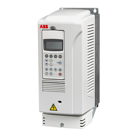
22 Operation principle and hardware description Product overview The ACS800-01/U1 is a wall mountable drive for AC motors. Control panel CDP 312R Heat sink Front cover Connection box IP21 (UL type 1) Control panel CDP 312R Heat sink under a hinged plastic cover Front cover (no connection box) IP55 (UL type 12) -
Page 25: Type Code
Operation principle and hardware description 23 Type code The type code contains information on the specifications and configuration of the drive. The first digits from the left are the basic configuration (for example, ACS800-01-0006-5). The optional selections are given next and separated by + signs (for example, +E202). -
Page 26: Main Circuit And Control
24 Operation principle and hardware description Main circuit and control Diagram This diagram shows the control interfaces and the main circuit of the drive. Drive Motor Option module 1: RMBA, RAIO, control RDIO, RDNA, RLON, RIBA, RPBA, and I/O RCAN, RCNA, RMBP, RETA, RECA, board REPL, RRIA or RTAC... -
Page 27: Printed Circuit Boards
Operation principle and hardware description 25 Printed circuit boards The drive contains the following printed circuit boards as standard: • Main circuit board (RINT) • Motor control and I/O board (RMIO) • EMC filter board (RRFC) when EMC equipment is selected or varistor board (RVAR) otherwise •... - Page 28 26 Operation principle and hardware description...
-
Page 29: Mechanical Installation
Mechanical installation 27 Mechanical installation What this chapter contains This chapter contains unpacking instructions, the delivery checklist and the mechanical installation instructions of the drive. Unpacking the unit The drive is delivered in either in a cardboard box or in a plywood package. The package also contains: •... -
Page 30: Example 1
28 Mechanical installation Example 1 To divide the box into two sections, pull from the spots marked with arrows. 2. Remove the upper box section. 3. Remove the unit and other contents from the box. Pull Do not lift by the cover. -
Page 31: Example 2
Mechanical installation 29 Example 2 Cut the straps. 2. Remove the outer box and sleeve. 3. Remove the locking sheet and the screws that attach the unit to the bottom pallet. -
Page 32: Checking The Delivery
30 Mechanical installation Checking the delivery Unpacking the unit Make sure that all items listed in (page 27) are present. Make sure that there are no signs of damage. Before installation and operation, read the information on the type designation label to make sure that the unit is of the correct type. -
Page 33: Free Space Around The Unit
Mechanical installation 31 Free space around the unit Required free space around the drive to enable cooling air flow, service and maintenance is shown below in millimeters and [inches]. When you install IP55 units above one another, leave 200 mm (7.9 in.) of free space above and below the unit. 50 [2.0] 200 [7.9] 50 [2.0]... -
Page 34: Mounting The Drive On The Wall
32 Mechanical installation Mounting the drive on the wall Units without vibration dampers Mark the locations for the four holes. The mounting points are shown in Dimensional drawings (page 133). In frame sizes R2 to R5 (IP21, UL type 1), use the mounting template on the package. -
Page 35: Cabinet Installation
Mechanical installation 33 Cabinet installation For better cooling, remove the front cover if it is installed in a cabinet. The required distance between parallel units is 5 mm (0.2 in.) in installations without the front cover. The cooling air entering the unit must not exceed +40 °C (+104 °F). Preventing cooling air recirculation ... - Page 36 34 Mechanical installation...
-
Page 37: Planning The Electrical Installation
The installation must always be designed and done according to applicable local laws and regulations. ABB does not assume any liability whatsoever for any installation which breaches the local laws and/or other regulations. Furthermore, if the recommendations given by ABB are not followed, the drive may experience problems that the warranty does not cover. -
Page 38: Motor Selection And Compatibility
36 Planning the electrical installation Motor selection and compatibility Technical data Select the motor according to the rating tables in (page 105). Use the DriveSize PC tool if the default load cycles are not applicable. 2. Make sure that the motor ratings are in the allowed ranges of the drive control program: •... -
Page 39: Protecting The Motor Insulation And Bearings
To avoid damage to motor bearings, the select and install the cables according to the instructions in the hardware manual. In addition, insulated N-end (non-driven end) bearings and output filters from ABB must be used according to the following table. -
Page 40: Requirements Table
The requirements table shows how to select the motor insulation system and when an optional ABB d filter, insulated N-end (non-driven end) motor bearings and ABB common mode filters are required. Ignoring the requirements or improper installation may shorten motor life or damage the motor bearings and voids the warranty. - Page 41 Planning the electrical installation 39 Motor Nominal mains Requirement for type voltage (AC line Motor insulation ABB d filter, insulated N-end bearing and ABB voltage) system common mode filter < 100 kW 100 kW < < > 350 kW 350 kW or frame size >...
- Page 42 Note 3: The rated output power of high output motors is higher than what is stated for the particular frame size in EN 50347:2001. This table shows the requirements for ABB random-wound motor series (for example, M3AA, M3AP and M3BP).
- Page 43 All AMA machines (manufactured in Helsinki) for drive systems have form-wound windings. All HXR machines manufactured in Helsinki starting 1.1.1998 have form- wound windings. ABB motors of types other than M2_, M3_, HX_ and AM_ Note 6: Use the selection criteria given for non-ABB motors.
-
Page 44: Permanent Magnet Motor
Note 10: Common mode filter is available as a separate option. Permanent magnet motor You can connect only one permanent magnet motor to the inverter output. ABB recommends a safety switch between the permanent magnet motor and the drive output. The switch isolates the motor during maintenance work. -
Page 45: Supply Connection
Planning the electrical installation 43 Supply connection Disconnecting device Install a hand-operated input disconnecting device between the AC power source and the drive. The disconnecting device must be of a type that can be locked to the open position for installation and maintenance work. To meet the European Union Directives, according to standard EN 60204-1, Safety of Machinery, the disconnecting device must be one of the following types: •... -
Page 46: Thermal Overload And Short-Circuit Protection
44 Planning the electrical installation Thermal overload and short-circuit protection Thermal overload protection of the drive and the input and motor cables The drive protects itself and the input and motor cables against thermal overload when the cables are dimensioned according to the nominal current of the drive. No additional thermal protection devices are needed. -
Page 47: Protecting The Motor And Motor Cable In Short Circuits
The drive protects the motor cable and motor in a short-circuit situation when: • the motor cable is sized correctly • the motor cable type complies with the motor cable selection guidelines by ABB • the cable length does not exceed the allowed maximum length specified for the drive •... -
Page 48: Protection Against Short Circuits In The Drive Or Supply Cable
Circuit breakers which have been tested by ABB with the ACS800 can be used. Fuses must be used with other circuit breakers. Contact your local ABB representative for the approved breaker types and supply network characteristics. -
Page 49: Ground Fault Protection
Planning the electrical installation 47 Ground fault protection The drive has ground fault protection in the motor and motor cable. This is not a personal safety or a fire protection feature. The ground fault protection can be disabled with a parameter, refer to the applicable firmware manual. The EMC filter of the drive has capacitors between the main circuit and the frame. -
Page 50: Safe Torque Off (Option +Q967)
48 Planning the electrical installation Safe torque off (option +Q967) The drive supports the Safe torque off (STO) function according to these standards: • EN 61800-5-2:2007 • EN ISO 13849-1:2008 • IEC 61508 • IEC 61511:2004 • EN 62061:2005 The function also corresponds to an uncontrolled stop in accordance with category 0 of EN 60204-1 and Prevention of unexpected start-up of EN 1037. -
Page 51: Safe Torque Off Circuit Diagram
Planning the electrical installation 49 Safe torque off circuit diagram 3AUA0000072271... -
Page 52: Selecting The Power Cables
Longer cables cause a motor voltage decrease which limits the available motor power. The decrease depends on the motor cable length and characteristics. Contact ABB for more information. Note that a sine filter (optional) at the drive output also causes a voltage decrease. -
Page 53: Alternative Power Cable Types
Planning the electrical installation 51 Alternative power cable types Power cable types that can be used with the drive are represented below. Recommended A separate PE conductor is required if the Symmetrical shielded cable: three phase conductivity of the cable shield is < 50% conductors and a concentric or otherwise of the conductivity of the phase symmetrically constructed PE conductor, and a... -
Page 54: Motor Cable Shield
52 Planning the electrical installation Motor cable shield If the motor cable shield is used as the sole protective earth conductor of the motor, ensure that the conductivity of the shield is sufficient. See IEC 61439-1. To effectively suppress radiated and conducted radio-frequency emissions, the shield conductivity must be at least 1/10 of the phase conductor conductivity. -
Page 55: Power Factor Compensation Capacitors
Planning the electrical installation 53 Power factor compensation capacitors Power factor compensation is not needed with AC drives. However, if a drive is to be connected in a system with compensation capacitors installed, note the following restrictions. WARNING! Do not connect power factor compensation capacitors or harmonic filters to the motor cables (between the drive and the motor). -
Page 56: Using A Contactor Between The Drive And The Motor
54 Planning the electrical installation Using a contactor between the drive and the motor Implementing the control of the output contactor depends on how you select the drive to operate. When you have selected to use DTC motor control mode, and motor ramp stop, open the contactor as follows: Give a stop command to the drive. -
Page 57: Tive Loads
Planning the electrical installation 55 Protecting the relay output contacts and attenuating disturbances in case of inductive loads Inductive loads (relays, contactors, motors) cause voltage transients when switched off. The relay contacts on the RMIO board are protected with varistors (250 V) against overvoltage peaks. -
Page 58: Selecting The Control Cables
Germany) has been tested and approved by ABB. Control panel cable In remote use, the cable connecting the control panel to the drive must not exceed 3 m (10 ft). The cable type tested and approved by ABB is used in control panel option kits. -
Page 59: Connection Of A Motor Temperature Sensor To The Drive I/O
Planning the electrical installation 57 Connection of a motor temperature sensor to the drive WARNING! IEC 61800-5-1 requires double or reinforced insulation between live parts when: • the accessible parts are non-conductive, or • the accessible parts are conductive, but not connected to the protective earth. -
Page 60: Routing The Cables
58 Planning the electrical installation Routing the cables Route the motor cable away from other cable routes. Motor cables of several drives can be run in parallel installed next to each other. It is recommended that the motor cable, input power cable and control cables be installed on separate trays. Avoid long parallel runs of motor cables with other cables in order to decrease electromagnetic interference caused by the rapid changes in the drive output voltage. -
Page 61: Electrical Installation
Electrical installation 59 Electrical installation What this chapter contains This chapter describes the electrical installation procedure of the drive. WARNING! The work described in this chapter may only be carried out by a Safety instructions qualified electrician. Obey the (page 9) in this manual. Ignoring the safety instructions can cause injury or death. -
Page 62: Motor And Motor Cable
1000 V DC. The insulation resistance of an ABB motor must be more than 100 Mohm (reference value at 25 °C or 77 °F). For the insulation resistance of other motors, please consult the manufacturer’s instructions. -
Page 63: Connecting The Power Cables
Electrical installation 61 Connecting the power cables Diagram Drive OUTPUT INPUT UDC+ V1 W1 V2 W2 (PE) (PE) External brake For alternatives, see resistor Disconnecting device Motor (page 43). 1), 2) Grounding of the motor cable shield at the motor end If shielded cable is used (not required but For minimum radio frequency interference: recommended), use a separate PE cable (1) -
Page 64: Conductor Stripping Lengths
62 Electrical installation Conductor stripping lengths Strip the conductor ends as follows to fit them inside the power cable connection terminals. Frame size Stripping length R2, R3 0.39 R4, R5 0.63 1.10 Allowed wire sizes, tightening torques Cable entries (page 118). - Page 65 Electrical installation 63 Connection box (IP21) Attaching hooks Back plate Attaching screws 360-degree grounding clamp Grommet Motor cable entry Input cable entry Brake resistor cable entry Control cable entry Attach the Bottom plate control cables between these plates with Cover cable ties.
- Page 66 64 Electrical installation Frame size R5 UDC+ UDC-...
- Page 67 Electrical installation 65 Frame size R6: Cable lug installation [16 to 70 mm (6 to 2/0 AWG) cables] Remove the screw terminals. Attach the cable lugs to the remaining bolts with M10 nuts. Isolate the ends of the cable lugs with Connection plate insulating tape or screws...
-
Page 68: Wall-Mounted Units (Us Version)
66 Electrical installation Wall-mounted units (US version) Remove the front cover (in frame size R6 the lower front cover) by releasing the retaining clip with a screw driver and lifting the cover from the bottom outwards. 2. Make the cable entry holes in the gland box by breaking off the suitable knock-out plates with a screw driver. -
Page 69: Warning Sticker
Electrical installation 67 Wire size Compression lug Crimping tool MCM/AWG Manufacturer Type Manufacturer Type No. of crimps Burndy YAV6C-L2 Burndy MY29-3 Ilsco CCL-6-38 Ilsco ILC-10 Burndy YA4C-L4BOX Burndy MY29-3 Ilsco CCL-4-38 Ilsco MT-25 Burndy YA2C-L4BOX Burndy MY29-3 Ilsco CRC-2 Ilsco IDT-12 Ilsco CCL-2-38... -
Page 70: Cabinet Installation (Ip21, Ul Type 1)
68 Electrical installation Cabinet installation (IP21, UL type 1) You can install the drive in a cabinet without the connection box and front cover. ABB recommends: • Ground the cable shield 360 degrees at the cabinet entry. • Lead the cable unstripped as close to the terminals as possible. -
Page 71: Frame Size R6
Electrical installation 69 Frame size R6 Cover the power cable terminals as follows: Cut holes for the installed cables into the clear plastic shroud in cable lug installations. Press the shroud onto the terminals. View of cable terminal installation Removal of the shroud by lifting up with a screw driver from the corner:... -
Page 72: Connecting The Control Cables
70 Electrical installation Connecting the control cables Lead the cable through the control cable entry (1). Connect the control cables as described below. Connect the conductors to the Motor control and I/O appropriate detachable terminals of the RMIO board (refer to board (RMIO) on page 85). - Page 73 Electrical installation 71 Frame sizes R5 and R6 View of frame size R6 Control panel Option module 2 DDCS communication option module 3: Option module 1 RDCO Place the warning sticker here Control cable Detachable connection terminals (pull up) grounding: see 360-degree Terminal for optional Prevention of grounding...
-
Page 74: 360-Degree Grounding
72 Electrical installation 360-degree grounding Insulation Double-shielded cable Single-shielded cable When the outer surface of the shield is covered with non-conductive material: Strip the cable carefully (do not cut the grounding wire and the shield). 2. Turn the shield inside out to expose the conductive surface. 3. -
Page 75: Cabling Of I/O And Fieldbus Modules
Electrical installation 73 Cabling of I/O and fieldbus modules Module As short as possible Shield Note: The RDIO module does not include a terminal for cable shield grounding. Ground the pair cable shields here. Pulse encoder module cabling As short as possible Note 1: If the encoder is of... -
Page 76: Attaching The Control Cables And Covers
74 Electrical installation Attaching the control cables and covers When all control cables are connected, attach them together with cable ties. Units with a connection box: Attach the cables to the entry plate with cable ties. Units with a gland box: tighten the clamping nuts of the cable glands. Attach the connection box cover. -
Page 77: Installation Of The Agps Board (Prevention Of Unexpected Start-Up, +Q950)
Installation of the AGPS board (Prevention of unexpected start-up, +Q950) 75 Installation of the AGPS board (Prevention of unexpected start-up, +Q950) What this chapter contains This chapter describes electrical installation of the optional Prevention of unexpected start-up function (+Q950) of the drive, and gives instructions for starting up, validating and using the function. - Page 78 76 Installation of the AGPS board (Prevention of unexpected start-up, +Q950) WARNING! The supply voltage for the AGPS board is 230 V AC. If the board is supplied with 24 V DC, the board is damaged and it needs to be replaced. The following figure shows how the external AGPS board is connected to the drive.
- Page 79 Installation of the AGPS board (Prevention of unexpected start-up, +Q950) 77 Connect the AGPS board as follows: • Remove the enclosure cover by undoing the fixing screws (1). • Ground the unit via the bottom plate of the enclosure or via terminal X1:1 of the AGPS board.
-
Page 80: Circuit Diagram
78 Installation of the AGPS board (Prevention of unexpected start-up, +Q950) Circuit diagram This circuit diagram shows how the AGPS-11 kit is installed. 3AFE00374994... -
Page 81: Start-Up And Validation
Installation of the AGPS board (Prevention of unexpected start-up, +Q950) 79 Start-up and validation Action Safety instructions Obey the safety instructions, see (page 9). Make sure that the drive can be run and stopped freely during the start-up. Stop the drive (if it operates), switch the input power off and isolate the drive from the power line by a disconnector. - Page 82 80 Installation of the AGPS board (Prevention of unexpected start-up, +Q950)
-
Page 83: Installation Of The Asto Board (Safe Torque Off, +Q967)
Installation of the ASTO board (Safe torque off, +Q967) 81 Installation of the ASTO board (Safe torque off, +Q967) What this chapter contains This chapter describes the electrical installation of the optional Safe torque off function (+Q967) of the drive and the specifications of the board. Safe torque off (+Q967) The optional Safe torque off function includes an external ASTO board, which is connected to the drive and an external power supply. - Page 84 82 Installation of the ASTO board (Safe torque off, +Q967) WARNING! The supply voltage for the ASTO-11C board is 24 V DC. If the board is supplied with 230 V AC, the board is damaged and it needs to be replaced.
- Page 85 Installation of the ASTO board (Safe torque off, +Q967) 83 Connect the ASTO board as follows: • Remove the cover of the enclosed ASTO unit by undoing the fixing screws (1). • Ground the ASTO unit via the bottom plate of the enclosure or via terminal X1:2 or X1:4 of the ASTO board.
-
Page 86: Circuit Diagram
84 Installation of the ASTO board (Safe torque off, +Q967) Circuit diagram The diagram below shows the connection between the ASTO board and the drive when it is ready. For an example diagram of a complete Safe torque off circuit, see page 49. -
Page 87: Motor Control And I/O Board (Rmio)
Motor control and I/O board (RMIO) 85 Motor control and I/O board (RMIO) What this chapter contains This chapter shows the • external control connections to the RMIO board for the ACS800 Standard Control Program (Factory Macro) • specifications of the inputs and outputs of the board. Note on terminal labelling Option modules (Rxxx) may have identical terminal designations with the RMIO board. -
Page 88: Parameter Settings
86 Motor control and I/O board (RMIO) WARNING! If the RMIO board is supplied from an external power source via terminal X34, the loose end of the cable removed from the RMIO board terminal must be secured mechanically to a location where it cannot come into contact with electrical parts. -
Page 89: External Control Connections (Non-Us)
Motor control and I/O board (RMIO) 87 External control connections (non-US) External control cable connections to the RMIO board for the ACS800 Standard Control Program (Factory Macro) are shown below. For external control connections of other control macros and programs, see the appropriate firmware manual. RMIO RMIO Terminal size:... -
Page 90: External Control Connections (Us)
88 Motor control and I/O board (RMIO) External control connections (US) External control cable connections to the RMIO board for the ACS800 Standard Control Program (Factory Macro US version) are shown below. For external control connections of other control macros and programs, see the appropriate firmware manual. -
Page 91: Rmio Board Specifications
Motor control and I/O board (RMIO) 89 RMIO board specifications Analogue inputs Two programmable differential current inputs (0 mA / 4 mA ... 20 mA, = 100 ohm) and one programmable differential voltage input (-10 V / 0 V / 2 V ... +10 V, = 200 kohm). -
Page 92: Relay Outputs
Insulation test voltage 4 kV AC, 1 minute DDCS fibre optic link With optional communication adapter module RDCO. Protocol: DDCS (ABB Distributed Drives Communication System) 24 V DC power input Voltage 24 V DC ± 10% Typical current... - Page 93 Motor control and I/O board (RMIO) 91 Isolation and grounding diagram (Test voltage: 500 V AC) VREF- AGND VREF+ AGND AI1+ Common mode AI1- voltage between AI2+ channels ±15 V AI2- AI3+ AI3- AO1+ AO1- AO2+ AO2- Jumper J1 settings: DGND1 All digital inputs share a common ground.
- Page 94 92 Motor control and I/O board (RMIO)
-
Page 95: Installation Checklist
Installation checklist 93 Installation checklist What this chapter contains This chapter contains an installation checklist. Checklist Check the mechanical and electrical installation of the drive before start-up. Go through the checklist below together with another person. WARNING! Only qualified electricians are allowed to commission the drive. Safety instructions Read and obey the (page 9) in this manual. - Page 96 94 Installation checklist Check that... ELECTRICAL INSTALLATION Planning the electrical installation Electrical installation (page 35), (page 59). The +E202 and +E200 EMC filter capacitors are disconnected if the drive is connected to an IT (ungrounded) system. Converter The capacitors are reformed if stored over one year, refer to modules with electrolytic DC capacitors in the DC link, Capacitor reforming instructions (3BFE64059629 [English]).
-
Page 97: Start-Up And Use
Start-up and use 95 Start-up and use What this chapter contains This chapter describes the start-up procedure and use of the drive. Start-up procedure Ensure that the installation of the drive has been checked according to the checklist in chapter Installation checklist, and that the motor and driven equipment are ready for start. -
Page 98: Control Panel
96 Start-up and use Control panel The user interface of the drive is the control panel (type CDP 312R). For more information on using the control panel, see the firmware manual delivered with the drive. Removing the control panel To remove the control panel from the panel holder, press down the locking clip and pull the panel out. -
Page 99: Maintenance
Ignoring the safety instructions can cause injury or death. Maintenance intervals If installed in an appropriate environment, the drive requires very little maintenance. This table lists the routine maintenance intervals recommended by ABB. Interval Maintenance Instruction... -
Page 100: Heatsink
98 Maintenance Consult your local ABB Service representative for more details on the maintenance. On the Internet, go to http://www.abb.com/drives. Heatsink The heatsink fins pick up dust from the cooling air. The drive runs into overtemperature warnings and faults if the heatsink is not clean. In a “normal”... -
Page 101: Fan Replacement (R4)
Maintenance 99 Fan replacement (R4) Loosen the screws that attach the fan mounting plate to the frame. 2. Push the fan mounting plate to the left and pull it out. 3. Disconnect the fan power cable. 4. Remove the screws that attach the fan to the fan mounting plate. 5. -
Page 102: Fan Replacement (R5)
100 Maintenance Fan replacement (R5) Remove the screw. 2. Open the swing-out frame and disconnect the cable. 3. Remove the screws of the fan. 4. Install the new fan in reverse order. -
Page 103: Fan Replacement (R6)
Maintenance 101 Fan replacement (R6) Note: In -0205-3 and 0255-5 units, access the fan through the opening in the support frame of the cable connection box. Remove the screw that attaches the fan casing and let the casing lean down against the limiters. -
Page 104: Additional Fan
102 Maintenance Additional fan There is an additional cooling fan in all IP55 units and most IP21 units. However, there is no additional fan in the following IP21 units: -0003-3, -0004-3, -0005-3, -0004-5, -0005-5 and -0006-5. The following IP55 units have two additional fans: -0205-3 and -0255-5. -
Page 105: Capacitors
It is not possible to predict a capacitor failure. Capacitor failure is usually followed by a mains fuse failure or a fault trip. Contact ABB if capacitor failure is suspected. Replacements for frame size R4 and up are available from ABB. Do not use other than ABB specified spare parts. - Page 106 104 Maintenance...
-
Page 107: Technical Data
Technical data 105 Technical data What this chapter contains This chapter contains the technical specifications of the drive, such as the ratings, sizes and technical requirements, provisions to fulfill the requirements for certifications, and the warranty policy. -
Page 108: Iec Data
106 Technical data IEC data Ratings The IEC ratings for the ACS800-01 with 50 Hz and 60 Hz supplies are given below. The symbols are described below the table. ACS800-01 Nominal Light-overload Heavy-duty use Frame Air flow Heat dis- overload size ratings... - Page 109 Technical data 107 ACS800-01 Nominal Light-overload Heavy-duty use Frame Air flow Heat dis- overload size ratings size sipation cont.max cont.max Three-phase supply voltage 380 V, 400 V or 415 V -0003-3 -0004-3 -0005-3 10.8 -0006-3 10.9 13.8 10.2 -0009-3 13.9 17.6 12.7 -0011-3...
-
Page 110: Symbols
108 Technical data ACS800-01 Nominal Light-overload Heavy-duty use Frame Air flow Heat dis- overload size ratings size sipation cont.max cont.max Three-phase supply voltage 525 V, 550 V, 575 V, 600 V, 660 V or 690 V -0011-7 11.5 -0016-7 -0020-7 18.5 -0025-7 18.5... -
Page 111: Derating
Technical data 109 Derating The load capacity (current and power) decreases if the installation site altitude exceeds 1000 meters (3300 ft), or if the ambient temperature exceeds 40 °C (104 °F). Temperature derating In the temperature range +40 °C (+104 °F) to +50 °C (+122 °F) the rated output current is decreased 1% for every additional 1 °C (1.8 °F). - Page 112 110 Technical data ACS800- Input Fuse 01 size current Manufacturer Type IEC size Three-phase supply voltage 208 V, 220 V, 230 V or 240 V -0001-2 ABB Control OFAF000H10 -0002-2 ABB Control OFAF000H10 -0003-2 ABB Control OFAF000H10 -0004-2 ABB Control OFAF000H16...
-
Page 113: Frame Sizes R5 And R6
Technical data 111 Frame sizes R5 and R6 Quick guide for Choose between gG and aR fuses according to the table under selecting between gG and aR fuses (page 115), or verify the operating time by checking that the short-circuit current of the installation is at least the value given in the fuse table. -
Page 114: Fuse Tables For Frame Sizes R5 And R6
2 · The calculated short-circuit current 2.7 kA is higher than the minimum short-circuit current of the drive gG fuse type OFAF00H160 (2400 A). -> The 500 V gG fuse (ABB Control OFAF00H160) can be used. Fuse tables for frame sizes R5 and R6... - Page 115 Manufacturer Type IEC size Three-phase supply voltage 380 V, 400 V, 415 V, 440 V, 460 V, 480 V or 500 V -0050-5 1050 34500 ABB Control OFAF000H80 -0060-5 1480 63600 ABB Control OFAF000H100 -0070-5 1940 103000...
-
Page 116: Ultrarapid (Ar) Fuses
114 Technical data Ultrarapid (aR) fuses ACS800-01 size Input Min. Fuse current short- circuit current Manufacturer Type IEC size Three-phase supply voltage 208 V, 220 V, 230 V or 240 V -0025-2 4650 Bussmann 170M1567D DIN000 -0030-2 8500 Bussmann 170M1568D DIN000 -0040-2 8500... -
Page 117: Quick Guide For Selecting Between Gg And Ar Fuses
Technical data 115 Quick guide for selecting between gG and aR fuses The table below is a short cut in selecting between gG and aR fuses. The combinations (cable size, cable length, transformer size and fuse type) in the table fulfill the minimum requirements for the proper operation of the fuse. - Page 118 Selection of smaller fuses improves the protection, but can also affect the fuse life time and lead to unnecessary operation of the fuses. In case of any uncertainty regarding the drive protection, please contact your local ABB.
-
Page 119: Cable Types
Technical data 117 Cable types The table below gives copper and aluminum cable types for different load currents. Cable sizing is based on max. 9 cables laid on a cable ladder side by side, ambient temperature 30 °C (86 °F), PVC insulation, surface temperature 70 °C (158 °F) (EN 60204-1 and IEC 60364-5-52:2001). -
Page 120: Cable Entries
118 Technical data Cable entries Brake resistor, mains and motor cable terminal sizes (per phase), accepted cable diameters and tightening torques are given below Fram Earthing PE U1, V1, W1, U2, V2, W2, R+, R Wire size Max. cable Cable Ø... -
Page 121: Nema Data
Technical data 119 NEMA data Ratings The NEMA ratings for the ACS800-U1 with 60 Hz supplies are given below. The symbols are described below the table. For sizing, derating and 50 Hz supplies, see IEC data (page 106). ACS800-U1 size... -
Page 122: Symbols
120 Technical data ACS800-U1 size Normal use Heavy-duty use Frame Air flow Heat dissi- size pation BTU/Hr /min Three-phase supply voltage 525 V, 575 V, 600 V -0011-7 11.5 1050 -0016-7 1200 -0020-7 1550 15/20 -0025-7 1850 -0030-7 2100 25/30... -
Page 123: Fuses
Note 3: Larger fuses must not be used. Note 4: Fuses from other manufacturers can be used if they meet the ratings and the melting curve of the fuse does not exceed the melting curve of the fuse mentioned in the table. ACS800-U1 Frame size Input... -
Page 124: Cable Types
122 Technical data ACS800-U1 Frame size Input Fuse type current Manufacturer Type UL class Three-phase supply voltage 525 V, 575 V, 600 V -0011-7 Bussmann JJS-20 -0016-7 Bussmann JJS-20 -0020-7 Bussmann JJS-30 -0025-7 Bussmann JJS-30 -0030-7 Bussmann JJS-45 -0040-7 Bussmann... -
Page 125: Cable Entries
Technical data 123 Cable entries Brake resistor, input and motor cable (per phase) terminal sizes, accepted cable diameters and tightening torques are given below Frame Earthing PE U1, V1, W1, U2, V2, W2, R+, R size Wire size Knock-out hole Tightening Wire size Tightening... -
Page 126: Input Power Connection
124 Technical data Input power connection Voltage ( 208/220/230/240 V AC 3-phase ± 10% for 230 V AC units 380/400/415 V AC 3-phase ± 10% for 400 V AC units 380/400/415/440/460/480/500 V AC 3-phase ± 10% for 500 V AC units 525/550/575/600/660/690 V AC 3-phase ±... -
Page 127: Energy Efficiency Data (Ecodesign)
Technical data 125 Energy efficiency data (ecodesign) Energy efficiency data according to IEC 61800-9-2 is available from the ecodesign tool (https://ecodesign.drivesmotors.abb.com). Cooling Method Internal fan, flow direction from bottom to top. Mechanical installation Free space around the (page 27). unit Degree of protection IP21 (UL type 1) and IP55 (UL type 12). -
Page 128: Ambient Conditions
126 Technical data Ambient conditions Environmental limits for the drive are given below. The drive is to be used in a heated, indoor, controlled environment. Operation Storage Transportation installed for stationary in the protective in the protective package package Installation site altitude 0 to 4000 m (13123 ft) above sea level [above 1000 m (3281 ft), see... -
Page 129: Materials
IEC 62635 guidelines. To aid recycling, plastic parts are marked with an appropriate identification code. Contact your local ABB distributor for further information on environmental aspects and recycling instructions for professional recyclers. End of life treatment must follow international and local regulations. -
Page 130: Ce Marking
128 Technical data CE marking A CE mark is attached to the drive to verify that the unit follows the provisions of the European Low Voltage and EMC Directives. The CE marking also verifies that the drive, in regard to its safety functions (such as Safe torque off), conforms with the Machinery Directive as a safety component. -
Page 131: First Environment (Drive Of Category C2)
Technical data 129 First environment (drive of category C2) The drive complies with the standard with the following provisions: The drive has EMC filter +E202. 2. The motor and control cables are selected as specified in the hardware manual. 3. The drive is installed according to the instructions given in the hardware manual. 4. -
Page 132: Second Environment (Drive Of Category C4)
Equipment 2. An EMC plan for preventing disturbances is drawn up for the installation. A template is available from the local ABB representative. 3. The motor and control cables are selected as specified in the hardware manual. 4. The drive is installed according to the instructions given in the hardware manual WARNING! A drive of category C4 is not intended to be used on a low- voltage public network which supplies domestic premises. -
Page 133: Ul/Csa Markings
Technical data 131 UL/CSA markings The ACS800-01 and ACS800-U1 units of UL type 1 are cULus listed and CSA marked. UL checklist • The drive is to be used in a heated, indoor controlled environment. The drive must be installed in clean air according to enclosure classification. Cooling air must be clean, free from corrosive materials and electrically conductive dust. - Page 134 Notwithstanding any other provision to the contrary and regardless of whether the contract is terminated or not, ABB and its affiliates are under no circumstances liable for damages and/or losses related to such security breaches, any unauthorized access, interference, intrusion, leakage and/or theft of data or information.
-
Page 135: Dimensional Drawings
Dimensional drawings 133 Dimensional drawings Dimensional drawings of the ACS800-01 are shown below. The dimensions are given in millimeters and [inches]. -
Page 136: Frame Size R2 (Ip21, Ul Type 1)
134 Dimensional drawings Frame size R2 (IP21, UL type 1) -
Page 137: Frame Size R2 (Ip55, Ul Type 12)
Dimensional drawings 135 Frame size R2 (IP55, UL type 12) -
Page 138: Frame Size R3 (Ip21, Ul Type 1)
136 Dimensional drawings Frame size R3 (IP21, UL type 1) -
Page 139: Frame Size R3 (Ip55, Ul Type 12)
Dimensional drawings 137 Frame size R3 (IP55, UL type 12) -
Page 140: Frame Size R4 (Ip21, Ul Type 1)
138 Dimensional drawings Frame size R4 (IP21, UL type 1) -
Page 141: Frame Size R4 (Ip55, Ul Type 12)
Dimensional drawings 139 Frame size R4 (IP55, UL type 12) -
Page 142: Frame Size R5 (Ip21, Ul Type 1)
140 Dimensional drawings Frame size R5 (IP21, UL type 1) -
Page 143: Frame Size R5 (Ip55, Ul Type 12)
Dimensional drawings 141 Frame size R5 (IP55, UL type 12) -
Page 144: Frame Size R6 (Ip21, Ul Type 1)
142 Dimensional drawings Frame size R6 (IP21, UL type 1) -
Page 145: Frame Size R6 (Ip21, Ul Type 1), -205-3 And -255-5 Units
Dimensional drawings 143 Frame size R6 (IP21, UL type 1), -205-3 and -255-5 units Frame size R6 (IP21, Note: Only measurements that differ from those of the standard UL type 1) are given below. -
Page 146: Frame Size R6 (Ip55, Ul Type 12)
144 Dimensional drawings Frame size R6 (IP55, UL type 12) For types -0205 and -0255-5, see page 145. -
Page 147: Frame Size R6 (Ip55, Ul Type 12) -0205-3 And -0255-5 Units
Dimensional drawings 145 Frame size R6 (IP55, UL type 12) -0205-3 and -0255-5 units... -
Page 148: Dimensional Drawings (Usa)
146 Dimensional drawings Dimensional drawings (USA) Dimensional drawings of the ACS800-U1 are shown below. The dimensions are given in millimeters and [inches]. -
Page 149: Frame Size R2 (Ul Type 1, Ip21)
Dimensional drawings 147 Frame size R2 (UL type 1, IP21) ... -
Page 150: Frame Size R2 (Ul Type 12, Ip55)
148 Dimensional drawings Frame size R2 (UL type 12, IP55) ... -
Page 151: Frame Size R3 (Ul Type 1, Ip21)
Dimensional drawings 149 Frame size R3 (UL type 1, IP21) ... -
Page 152: Frame Size R3 (Ul Type 12, Ip55)
150 Dimensional drawings Frame size R3 (UL type 12, IP55) ... -
Page 153: Frame Size R4 (Ul Type 1, Ip21)
Dimensional drawings 151 Frame size R4 (UL type 1, IP21) ... -
Page 154: Frame Size R4 (Ul Type 12, Ip55)
152 Dimensional drawings Frame size R4 (UL type 12, IP55) ... -
Page 155: Frame Size R5 (Ul Type 1, Ip21)
Dimensional drawings 153 Frame size R5 (UL type 1, IP21) ... -
Page 156: Frame Size R5 (Ul Type 12, Ip55)
154 Dimensional drawings Frame size R5 (UL type 12, IP55) ... -
Page 157: Frame Size R6 (Ul Type 1, Ip21)
Dimensional drawings 155 Frame size R6 (UL type 1, IP21) ... -
Page 158: Frame Size R6 (Ul Type 1, Ip21) -0205-3 And -0255-5 Units
156 Dimensional drawings Frame size R6 (UL type 1, IP21) -0205-3 and -0255-5 units Frame size R6 (UL Note: Only measurements that differ from those of the standard type 1, IP21) are given below. -
Page 159: Frame Size R6 (Ul Type 12, Ip55)
Dimensional drawings 157 Frame size R6 (UL type 12, IP55) For types -0205 and -0255-5, see page 158. -
Page 160: Frame Size R6 (Ul Type 12, Ip55) -0205-3 And -0255-5 Units
158 Dimensional drawings Frame size R6 (UL type 12, IP55) -0205-3 and -0255-5 units ... -
Page 161: Agps Board (Option +Q950)
Dimensional drawings 159 AGPS board (option +Q950) -
Page 162: Asto Board With Enclosure (Option +Q967)
160 Dimensional drawings ASTO board with enclosure (option +Q967) -
Page 163: Resistor Braking
Resistor braking 161 Resistor braking What this chapter contains This chapter describes how to select, protect and wire brake choppers and resistors. The chapter also contains the technical data. Availability of brake choppers and resistors for the ACS800 Frame R2 and R3 drives and 690 V units of frame size R4 have a built-in brake chopper as standard equipment. - Page 164 162 Resistor braking the drive selection also). The following condition must be met: > P where denotes , or depending on the duty cycle. br10 br30 br60 brcont 3. Check the resistor selection. The energy generated by the motor during a 400- second period must not exceed the resistor heat dissipation capacity If the value is not sufficient, it is possible to use a four-resistor assembly in which two standard...
-
Page 165: Optional Brake Chopper And Resistor(S) For The Acs800-01/U1
Optional brake chopper and resistor(s) for the ACS800- 01/U1 The nominal ratings for dimensioning the brake resistors for the ACS800-01 and ACS800-U1 are given below at an ambient temperature of 40 °C (104 °F). ACS800-01 type Braking power Brake resistor(s) - Page 166 164 Resistor braking ACS800-01 type Braking power Brake resistor(s) of the chopper ACS800-U1 type and the drive Type brcont Rcont (ohm) (kW) (kJ) (kW) 400 V units -0003-3 SACE08RE44 -0004-3 SACE08RE44 -0005-3 SACE08RE44 -0006-3 SACE08RE44 -0009-3 SACE08RE44 -0011-3 SACE15RE22 -0016-3...
-
Page 167: Resistor Installation And Wiring
Resistor braking 165 ACS800-01 type Braking power Brake resistor(s) of the chopper ACS800-U1 type and the drive Type brcont Rcont (ohm) (kW) (kJ) (kW) 690 V units -0011-7 SACE08RE44 -0016-7 SACE08RE44 -0020-7 SACE08RE44 -0025-7 SACE08RE44 -0030-7 SACE15RE22 -0040-7 SACE15RE22 22/33... -
Page 168: Protection Of Frame Sizes R2 To R5 (Acs800-01/U1)
Note: If an external brake chopper (outside the drive module) is used, a main contactor is always required. A thermal switch (standard in ABB resistors) is required for safety reasons. The cable must be shielded and not longer than the resistor cable. -
Page 169: Brake Circuit Commissioning
OFF2 STOP. For the use of the brake resistor overload protection (parameters 27.02...27.05), consult an ABB representative. WARNING! If the drive is equipped with a brake chopper but the chopper is not enabled by parameter setting, the brake resistor must be disconnected because the protection against resistor overheating is then not in use. - Page 170 168 Resistor braking...
-
Page 171: External +24 V Dc Power Supply For The Rmio Board Via Terminal X34
External +24 V DC power supply for the RMIO board via terminal X34 169 External +24 V DC power supply for the RMIO board via terminal What this chapter contains This chapter describes how to connect an external +24 V DC power supply for the RMIO board via terminal X34. -
Page 172: Connecting +24 V Dc External Power Supply
170 External +24 V DC power supply for the RMIO board via terminal X34 Connecting +24 V DC external power supply Break off the tab covering the +24 V DC power input connector with pliers. 2. Lift the connector upwards. 3. - Page 173 External +24 V DC power supply for the RMIO board via terminal X34 171 RMIO board RMIO board Connection of a two-way Connection of a three-way connector connector...
- Page 174 172 External +24 V DC power supply for the RMIO board via terminal X34...
-
Page 175: Rdco-01/02/03/04 Ddcs Communication Option Modules
RDCO-01/02/03/04 DDCS communication option modules 173 RDCO-01/02/03/04 DDCS communication option modules What this chapter contains This chapter contains a description of the RDCO-0x DDCS communication option module connections and the technical specifications of the RDCO-0x modules. Overview The RDCO-0x DDCS Communication options are add-on modules for the •... -
Page 176: Delivery Check
174 RDCO-01/02/03/04 DDCS communication option modules There are several types of the RDCO. The difference between the types is the optical components. In addition, each type is available with a coated circuit board, this being indicated by a “C” suffix, for example, RDCO-03C. Optical component type Module type RDCO-01(C) -
Page 177: Installation
RDCO-01/02/03/04 DDCS communication option modules 175 Installation WARNING! All electrical installation and maintenance work on the drive should be carried out by qualified electricians only. The drive and adjoining equipment must be properly earthed. Do not work on a powered drive. Before installation, switch off the mains and other dangerous voltages (for example, from external control circuits) to the drive. -
Page 178: Technical Data
176 RDCO-01/02/03/04 DDCS communication option modules vice versa. In case multiple devices are to be connected to one channel, they must be connected in a ring. Technical data Module types: RDCO-01(C), RDCO-02(C), RDCO-03(C), RDCO-04(C) Degree of protection: IP20 Ambient conditions: The applicable ambient conditions specified for the drive in its Hardware Manual are in effect. -
Page 179: Further Information
Product and service inquiries Address any inquiries about the product to your local ABB representative, quoting the type designation and serial number of the unit in question. A listing of ABB sales, support and service contacts can be found by navigating to abb.com/searchchannels... - Page 180 © Copyright 2023 ABB. All rights reserved. Specifications subject to change without notice.
Need help?
Do you have a question about the ACS800-U1 and is the answer not in the manual?
Questions and answers