Table of Contents
Advertisement
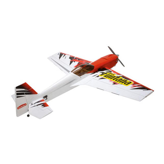
Funtana 125 ARF
Assembly Manual
Specifications
Wingspan ............................................................ 69.5 in (1765 mm)
Length................................................................. 68.5 in (1745 mm)
Wing Area ...................................................1108 sq in (71.5 sq dm)
Weight ...................................................... 8.0–8.5 lb (3.63–4.03 kg)
Engine Size ........................... .61–1.20 2-stroke; .90–1.25 4-stroke
Motor Size ...............................90–110 brushless outrunner Motor
Radio ......... 4-channels or more w/6 servos (5 w/electric option)
Advertisement
Table of Contents

Related Manuals for Hangar 9 Funtana 125


Summary of Contents for Hangar 9 Funtana 125
- Page 1 Funtana 125 ARF Assembly Manual Specifications Wingspan ............69.5 in (1765 mm) Length..............68.5 in (1745 mm) Wing Area ...........1108 sq in (71.5 sq dm) Weight ............8.0–8.5 lb (3.63–4.03 kg) Engine Size ......61–1.20 2-stroke; .90–1.25 4-stroke Motor Size .......90–110 brushless outrunner Motor...
-
Page 2: Table Of Contents
Safety, Precautions and Warnings ........54 HAN475012 Side Force Generators Warranty Information ............55 CE Compliance Information for the European Union ..56 2009 Official Academy of Model Aeronautics Safety Code ........56 Engine Mounting Template–Saito FG20 ......59 Hangar 9 Funtana 125 ARF Assembly Manual... -
Page 3: Included Parts Listing
-inch (450mm) clear plastic tube throttle linkage guide 2mm x 12mm phillips machine screw horn brackets to nylon clevis 2mm silver flat washers horn brackets to nylon clevis 2mm nylocks horn brackets to nylon clevis Hangar 9 Funtana 125 ARF Assembly Manual... -
Page 4: Using The Manual
DS9411 Digital Servo (2) (no mixing required) This manual is divided into sections to help make assembly The Funtana 125 ARF requires a minimum of a 4-channel • Y-harness (plugged into receiver) easier to understand, and to provide breaks between each radio to operate the functions of your aircraft. -
Page 5: Use The Correct Propeller
• Tru Turn Propeller Adapter (TRUTT0828A) Optional Side Force Generators • Fuel Dot (HAN115) Your Funtana 125 has been prepared to use the optional Side • Muffler 90-Degree Adapter (SAI125A140) Force Generators (HAN475012). In addition, you will need • JR Switch, Chargeswitch (JRPA004) to purchase four 3mm washers and four 3mm x 12mm hex •... -
Page 6: Important Information Regarding Warranty Information
Step 3 Hook and loop strap Pro, Hangar 9 P-51 and F-22 PTS. And as always, with the Place the rudder servo in the opening in the left side of the Foam rubber: 1/4-inch (6mm) Hangar Pack, you still get all the same great features that fuselage with the output of the servo facing toward the rear you did with the original aircraft. - Page 7 Hint: Tie a small piece of string or place a piece of tape on the end of the extension so you can differentiate the rudder lead from the elevator leads later in this section of the manual. Hangar 9 Funtana 125 ARF Assembly Manual...
- Page 8 A model for electric flight you can skip to the next section MatchBox, reverse servo, reversing Y-harness, or best of the manual. yet, a computer radio, will be required for the elevator servos. Hangar 9 Funtana 125 ARF Assembly Manual...
-
Page 9: Hinging The Elevators And Ailerons
Step 1 Locate the items required to hinge the elevators and ailerons. In addition, locate the hardware necessary to install the control horns at this time as well. Hangar 9 Funtana 125 ARF Assembly Manual... - Page 10 Align the center line of the horn aligned the wood. with the mark made in the previous step. Use a felt-tipped pen to transfer the location for the three mounting holes on the elevator. Hangar 9 Funtana 125 ARF Assembly Manual...
- Page 11 Position the elevator and stabilizer so their tips are aligned. Step 11 making a better bond between the hinge and surrounding Remove the T-pins from the hinges. wood. Slide the hinges into the elevator. Hangar 9 Funtana 125 ARF Assembly Manual...
- Page 12 The CA must be allowed to soak into the hinges. Using accelerator will not allow the CA enough time to correctly soak each hinge. Note: We used colored tape to illustrate the position of the hinge gap sealing tape. Hangar 9 Funtana 125 ARF Assembly Manual...
- Page 13 Align the center line of the horn aligned with the mark made in the previous step. Use a felt-tipped pen to transfer the location for the three mounting holes on the aileron. Hangar 9 Funtana 125 ARF Assembly Manual...
- Page 14 Remove the T-pins at this time. Note: The installation of the optional SFG's will be covered later in the manual. Hangar 9 Funtana 125 ARF Assembly Manual...
- Page 15 The CA must be allowed to soak into the hinges. Using accelerator will not allow the CA enough time to correctly soak each hinge. Note: We used colored tape to illustrate the position of the hinge gap sealing tape. Hangar 9 Funtana 125 ARF Assembly Manual...
-
Page 16: Rudder Installation
This hole must be at the high point of the rudder hinge line. If not, drill the hole deeper or make the included with your model. the hinge line as shown. notch deeper to fit the wire. Hangar 9 Funtana 125 ARF Assembly Manual... - Page 17 Hint: Use a toothpick to get the epoxy into the hole in the rudder. Note: Prior to installing the wire confirm that the wires are at 90 degrees to each other. If not it is much easier to adjust now prior to installation. Hangar 9 Funtana 125 ARF Assembly Manual...
- Page 18 Step 12 wood. Use a #1 Phillips screwdriver to thread a 2mm x 16mm self- tapping screw into each of the holes. This will cut threads in the wood. Hangar 9 Funtana 125 ARF Assembly Manual...
- Page 19 Important: Do not use accelerator on the hinges. The CA must be allowed to soak into the hinges. Using accelerator will not allow the CA enough time to correctly soak each hinge. Hangar 9 Funtana 125 ARF Assembly Manual...
- Page 20 Place 2–3 drops of thin CA into each hole to harden the Flex the rudder through its range of motion a few dozen surrounding wood. This will keep the screws from pulling times to break in the hinges. out of the fuselage. Hangar 9 Funtana 125 ARF Assembly Manual...
-
Page 21: Landing Gear Installation
Slide the tail wheel on the tail gear wire. Apply a small drop Step 1 of oil on the axle so the wheel can spin freely on the wire. Locate the items necessary to attach the landing gear that are included with your model. Hangar 9 Funtana 125 ARF Assembly Manual... - Page 22 Slide one of the 4mm wheel collars to the axle against the mounting flange of the axle as shown. Tighten the setscrew using a 1.5mm hex wrench. Use threadlock on the setscrew so it doesn’t vibrate loose in flight. Hangar 9 Funtana 125 ARF Assembly Manual...
- Page 23 4mm locknut while holding the axle at the flange with a 10mm open end wrench. Step 13 Repeat Steps 6 through 12 to prepare and install the remaining wheel and wheel pant. Hangar 9 Funtana 125 ARF Assembly Manual...
-
Page 24: Electric Motor Installation
Use a 2.5mm hex wrench to attach the X-mount to the rear pant to the landing gear. of the motor. Again, use threadlock on the screws. Step 1 Locate the items necessary to install the electric motor included with your model. Hangar 9 Funtana 125 ARF Assembly Manual... - Page 25 Attach the speed control to the side of the motor box using two-sided tape and tie wraps. Connect the appropriate leads from the speed control to the motor. Make sure the leads will not interfere with the operation of the motor. Hangar 9 Funtana 125 ARF Assembly Manual...
- Page 26 CG if needed. If the receiver battery requires moving, it will be easier to remove the battery tray to move the receiver pack. Once the tray is glued in, it will be difficult to access the receiver battery. Hangar 9 Funtana 125 ARF Assembly Manual...
-
Page 27: 2-Stroke Glow Engine Installation
Drill bit: 1/16-inch (1.5mm), 9/64-inch (3.5mm), Position the engine so the drive washer is 5 -inch (133mm) 5/32-inch (4mm) forward of the firewall. Step 1 Locate the items necessary to install the engine included with your model. Hangar 9 Funtana 125 ARF Assembly Manual... - Page 28 Use a drill and a 9/64-inch (3.5mm) drill bit to drill the hole inch (47mm). Use medium CA to glue the tube to the firewall in the firewall for the throttle pushrod tube. and the fuel tank mount. Hangar 9 Funtana 125 ARF Assembly Manual...
- Page 29 5/64-inch (2mm) drill bit to enlarge the hole in the servo horn that worked best for your throttle linkage installation. On our model we used the hole that was 9/16-inch (14mm) from the center of the servo horn. Hangar 9 Funtana 125 ARF Assembly Manual...
-
Page 30: 4-Stroke Glow Engine Installation
Step 18 Reinstall the servo horn by sliding the connector over the pushrod wire. Center the throttle stick and trim and install the servo horn perpendicular to the servo center line. Hangar 9 Funtana 125 ARF Assembly Manual... - Page 31 Also make sure the carburetor arm is facing to the top of the engine. Hint: It is recommended to use a drill press to drill the holes so they are straight in the mount. Hangar 9 Funtana 125 ARF Assembly Manual...
- Page 32 -inch (420mm) throttle pushrod tube at positions pushrod to the outer hole of the carburetor arm as shown. that are at one end of the tube and 4 -inch (115mm) from one end of the tube. Hangar 9 Funtana 125 ARF Assembly Manual...
- Page 33 5/64-inch (2mm) drill bit to enlarge the hole in the servo horn that worked best for your throttle linkage installation. On our model we used the hole that was 9/16-inch (14mm) from the center of the servo horn. Hangar 9 Funtana 125 ARF Assembly Manual...
- Page 34 Center the throttle stick and trim and install the servo horn perpendicular to the servo center line. Note: We used a 90 degree adapter to center the muffler to reduce the amount of cowling that will need to be removed. Hangar 9 Funtana 125 ARF Assembly Manual...
- Page 35 Use a hobby knife with a #11 blade and a rotary tool to cut two 3/4-inch (19mm) wide slots in the opposite side of the engine mounting box. These slots are centered and are 1/8- inch (3mm) from the top and bottom of the box. Hangar 9 Funtana 125 ARF Assembly Manual...
- Page 36 4 -inch (115mm) from one end of the tube. Use side cutters to trim the tube at the forward edge of the throttle servo. Hangar 9 Funtana 125 ARF Assembly Manual...
- Page 37 Make the necessary connections between the ignition protect it from vibration. module and engine. Use a tie wrap or two to keep the wires organized so they don’t interfere with the operation of the engine. Hangar 9 Funtana 125 ARF Assembly Manual...
- Page 38 Step 24 Reinstall the servo horn by sliding the connector over the pushrod wire. Center the throttle stick and trim and install the servo horn perpendicular to the servo center line. Hangar 9 Funtana 125 ARF Assembly Manual...
-
Page 39: Fuel Tank Installation
Select the tubing that best fits your engine’s fuel requirements. Note: We use d a 90 degree adapter to center the muffler to reduce the amount of cowling that will need to be removed. Hangar 9 Funtana 125 ARF Assembly Manual... - Page 40 This is necessary as the tubing will need to be wired on to prevent it from sliding loose. Hangar 9 Funtana 125 ARF Assembly Manual...
- Page 41 We used a fuel dot and a T-fitting on and stopper. the line to the carburetor so the tank can be fueled without removing the cowling. Hangar 9 Funtana 125 ARF Assembly Manual...
-
Page 42: Cowling Installation
This will allow air to pass through the cowl and over the engine or motor for cooling. The opening will measure 5 -inches by 3-inches (133mm x 76mm). Hangar 9 Funtana 125 ARF Assembly Manual... - Page 43 Use a 2.5mm hex wrench to tighten the screws. to mark the cowling. Hint: Slide a small 1/4-inch (6mm) piece of fuel tubing on each screw after sliding the washer in position. This will keep the screws from vibrating loose. Hangar 9 Funtana 125 ARF Assembly Manual...
-
Page 44: Rudder Linkage Installation
Slide the propeller on the engine shaft. Make sure to balance Secure the spinner cone to complete the cowling installation. the propeller before installation to reduce vibrations that could damage the engine or airframe. Hangar 9 Funtana 125 ARF Assembly Manual... - Page 45 Note: We have also included 3mm x 12mm socket head bolts and 3mm locknuts if you are not using JR or Hangar 9 servo horns on your model. Use a 2.5mm hex wrench and 5.5mm nut driver to tighten this hardware.
-
Page 46: Elevator Installation
Note: We have also included 3mm x 12mm socket head bolts and 3mm locknuts if you are not using JR or Hangar 9 servo horns on your model. Use a 2.5mm hex wrench and 5.5mm nut driver to tighten this hardware. - Page 47 2mm washers to secure the clevis to the elevator control horn. Use a #1 Phillips screwdriver and a 4mm nut driver to tighten the hardware. Don’t over-tighten the hardware causing the clevis to bind. Hangar 9 Funtana 125 ARF Assembly Manual...
-
Page 48: Aileron Servo Installation
This will cut threads in the wood for the next servo faces toward the aileron as shown. Step 1 step. Locate the items necessary to install the aileron servo included with your model. Hangar 9 Funtana 125 ARF Assembly Manual... - Page 49 Note: We have also included 3mm x 12mm socket head bolts and 3mm locknuts if you are not using JR or Hangar 9 servo horns on your model. Use a 2.5mm hex wrench and 5.5mm nut driver to tighten this hardware.
-
Page 50: Wing Installation
Locate the items necessary to attach the wing to the could possibly damage the wing. Slide the wing panel and tube into position on the fuselage. fuselage. Make sure to guide the aileron servo lead through the slot in the fuselage. Hangar 9 Funtana 125 ARF Assembly Manual... - Page 51 Repeat Steps 2 through 9 to install the remaining wing panel and fillet. Step 13 Repeat Step 11 and 12 to install the remaining side force generator on the opposite wing panel. Hangar 9 Funtana 125 ARF Assembly Manual...
-
Page 52: Center Of Gravity
This is the correct balance point for your model. You might find you may be required to add a small amount of weight to either the front or back of the fuselage to achieve the correct balance. Hangar 9 Funtana 125 ARF Assembly Manual... -
Page 53: Control Throws
Note: It is very important to reconnect the lines to the correct place. If they are reconnected incorrectly, the engine will not run properly. Hangar 9 Funtana 125 ARF Assembly Manual... -
Page 54: Safety Do's And Don'ts For Pilots
Check that all trim levers are in the proper location. Step 7 All servo pigtails and switch harness plugs should be secured in the receiver. Make sure that the switch harness moves freely in both directions. Hangar 9 Funtana 125 ARF Assembly Manual... -
Page 55: Warranty Information
Any repair left unpaid or unclaimed after 90 days will be considered abandoned and will be disposed of accordingly. Please note: non-warranty repair is only available on electronics and model engines. Hangar 9 Funtana 125 ARF Assembly Manual... -
Page 56: Ce Compliance Information For The European Union
Please call +49 4121 46199 66 or e-mail us at service@ devices and practices as defined within the Air Show horizonhobby.de with any questions or concerns regarding Advisory Committee Document. this product or warranty. Hangar 9 Funtana 125 ARF Assembly Manual... - Page 57 5. I will operate my model aircraft using only radio- control frequencies currently allowed by the Federal Communications Commission (FCC). Only individuals properly licensed by the FCC are authorized to operate equipment on Amateur Band frequencies. Hangar 9 Funtana 125 ARF Assembly Manual...
- Page 58 Hangar 9 Funtana 125 ARF Assembly Manual...
-
Page 59: Engine Mounting Template-Saito Fg20
Engine Mounting Template–Saito FG20 101.7mm Carb Vent 99.9mm Throttle 50mm Saito FG-20 Hangar 9 Funtana 125 ARF Assembly Manual... - Page 60 © 2009 Horizon Hobby, Inc. 4105 Fieldstone Road Champaign, Illinois 61822 (877) 504-0233 horizonhobby.com Hangar-9.com 15021-1 Printed 09/09...
Need help?
Do you have a question about the Funtana 125 and is the answer not in the manual?
Questions and answers