Table of Contents
Advertisement
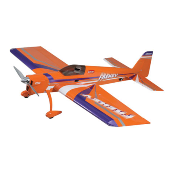
Specifications
Wingspan .................................... 61 in (1549.5mm)
Wing Area ......................... 1066 sq in (6.88 sq dm)
Length ......................................... 63.7 in (1618mm)
Weight .............................. 8–9.5 lb (3.6 kg–4.3 kg)
Frenzy 100
Assembly mAnuAl
Engine ................................... .91–1.25 Four-Stroke
Radio..............4-Channel w/5 Servos (4 for electric)
..................................... .61–1.00 Two-Stroke
........................Power 60–Power 110 Electric
Advertisement
Table of Contents

Related Manuals for Hangar 9 frenzy 100


Summary of Contents for Hangar 9 frenzy 100
- Page 1 Frenzy 100 Assembly mAnuAl Specifications Wingspan ........61 in (1549.5mm) Engine ........91–1.25 Four-Stroke Wing Area ......1066 sq in (6.88 sq dm) ........61–1.00 Two-Stroke Length ......... 63.7 in (1618mm) ......Power 60–Power 110 Electric Weight ......8–9.5 lb (3.6 kg–4.3 kg)
-
Page 2: Table Of Contents
Table of Contents Using the Manual ..............3 Required Tools and Adhesives . -
Page 3: Using The Manual
Before Starting Assembly Before beginning the assembly of the Frenzy 100, remove each part from its bag for inspection. Closely inspect the fuselage, wing panels, rudder, and stabilizer for damage. If you find any damaged or missing parts, contact the place of purchase. -
Page 4: Radio And Power Systems Requirements
Radio and Power Systems Requirements • 4-channel radio system (minimum) w/receiver • Large Servo Arms (JRPA212) (3 pkgs) • 6-Inch Servo Lead Extension (JRPA095) (2) • JR Charge Jack Switch (JRPA004) • 18-inch Servo Lead Extension (JRPA099) (3) • Y-harness (Ailerons) (JSP98020) (Required when using 4-channel radio) •... -
Page 5: Warranty Period
Warranty Period Exclusive Warranty- Horizon Hobby, Inc., (Horizon) warranties that the Products purchased (the "Product") will be free from defects in materials and workmanship at the date of purchase by the Purchaser. Limited Warranty (a) This warranty is limited to the original Purchaser ("Purchaser") and is not transferable. REPAIR OR REPLACEMENT AS PROVIDED UNDER THIS WARRANTY IS THE EXCLUSIVE REMEDY OF THE PURCHASER. -
Page 6: Questions, Assistance, And Repairs
Questions, Assistance, and Repairs Your local hobby store and/or place of purchase cannot provide warranty support or repair. Once assembly, setup or use of the Product has been started, you must contact Horizon directly. This will enable Horizon to better answer your questions and service you in the event that you may need any assistance. -
Page 7: Safety, Precautions, And Warnings
Safety, Precautions, and Warnings This model is controlled by a radio signal that is subject to interference from many sources outside your control. This interference can cause momentary loss of control so it is advisable to always keep a safe distance in all directions around your model, as this margin will help to avoid collisions or injury. -
Page 8: Stabilizer And Fin Installation
Stabilizer and Fin Installation Required Parts Step 3 • Fuselage • Wing Measure from each wing tip to the tips of the stabilizer. • Stabilizer • Fin The stabilizer is aligned when both measurements are equal as shown. • 1/4-20 x 2-inch nylon bolt Required Tools and Adhesives •... - Page 9 Stabilizer and Fin Installation Step 5 Step 7 Double-check the alignment of the stabilizer as described Mix up 1/2-ounce (15Ml) of 30-minute epoxy. Apply in Steps 1 through 4. Use a felt-tipped pen to trace the the epoxy to the exposed wood of the stabilizer on both outline of the fuselage onto the stabilizer.
-
Page 10: Hinging The Control Surfaces
Hinging the Control Surfaces Required Parts Step 2 • Fuselage • Wing Place a T-pin in the center of three of the hinges. • Elevator (2) • Rudder • Tail wheel assembly • CA hinge (17) Required Tools and Adhesives •... - Page 11 Hinging the Control Surfaces Step 4 Step 6 Slide the elevator into position on the hinges. The elevator Move the elevator through its range of motion, both up should be tight against the hinge line. Also check that the and down, to break in the hinges.
- Page 12 Hinging the Control Surfaces Step 8 Step 10 Use 30-minute epoxy to secure the tail wheel assembly to All that remains is to hinge the ailerons. They each use the fuselage as shown. four hinges, and the only item to watch for is binding of the aileron at the wing tip.
-
Page 13: Landing Gear Installation
Landing Gear Installation Required Parts Step 2 • Fuselage • #8 washer (4) Attach the landing gear axles to the landing gear. • 5/32-inch wheel collar (4) • #4 washer (2) • Landing gear axle w/nut (2) • Tail wheel •... - Page 14 Landing Gear Installation Step 4 Step 5 Attach the wheel to the axle using two 5-32-inch wheel Attach the wheel pant to the landing gear using a 4-40 x collars and two 3mm x 8mm screws. A wheel collar is 3/8-inch socket head screw and a #4 washer.
-
Page 15: Servo And Linkage Installation
Servo and Linkage Installation Required Parts Step 2 • Fuselage • Rudder Use the hardware provided with the servo to secure it in • Pushrod connector • Metal clevis (8) the fuselage as shown. You will want to drill 1/16-inch (1.5mm) holes for the servo screws and harden them with •... - Page 16 Servo and Linkage Installation Step 4 Step 5 Remove the backplate from the rudder control horn and Follow Steps 1 and 2 to install the elevator servos. attach the clevis to the horn. Secure the control horn to The output of the servos will face toward the front of the rudder using three 2-56 x 5/8-inch machine screws the fuselage.
- Page 17 Servo and Linkage Installation Step 7 Step 9 Assemble the left elevator linkage by placing a clevis Tie the string to the servo lead for the aileron servo. Use retainer onto four of the metal clevises. Thread 4-40 nuts the string to pull the servo lead out of the hole at the and the clevises onto the 5 -inch (140mm) pushrod...
- Page 18 Servo and Linkage Installation Step 10 Step 12 Use the hardware provided with the servo to secure it in With the radio on, align the aileron servo horn parallel position in the wing. to the hinge line. Connect the linkage between the servo and control horn.
-
Page 19: Glow Engine Installation
Glow Engine Installation Required Parts Step 2 • Fuselage • Engine mount (2) Position the engine on the mount so the drive washer is • #8 washer (8) • 8-32 locknut (4) 5-inches (127mm) forward of the firewall. Use a clamp to hold the engine in position. - Page 20 Glow Engine Installation Step 4 Step 6 Drill the locations marked in the previous step using a Slide the 17 -inch (450mm) pushrod tube into the drill and 11/64-inch (4.5mm) drill bit. fuselage. Use medium CA to secure the tube to the firewall with roughly 1/16-inch (1.5mm) of the tube exposed forward of the firewall.
- Page 21 Glow Engine Installation Step 8 Step 10 Slide a clevis retainer onto the nylon clevis and thread Make a Z-bend in the pushrod at the location marked in the clevis on the 12-inch (305mm) pushrod. Pass the the previous step. Attach the bend to the carburetor arm. pushrod into the tube and attach the clevis to the throttle servo horn.
- Page 22 Glow Engine Installation Step 13 Step 15 Attach the fuel line to the carburetor. We used a fuel dot to Make any necessary holes in the cowling to clear allow fueling of the tank from outside the cowling. the muffler, needle valve and to install the fuel dot.
-
Page 23: Electric Motor Installation
Electric Motor Installation Required Parts Step 2 • Fuselage • 3-point motor mount Attach the 3-point mount to the motor. Make note of the • #4 washer (2) • 4-40 blind nut (2) position of the long tab of the mount in relationship to the motor wires. - Page 24 Electric Motor Installation Step 4 Step 6 Assemble and install the plywood ESC mount to the Test fit the battery tray into the fuselage. Use 30-minute firewall using two 4-40 x 1/2-inch socket head screws, epoxy to glue the battery tray in the fuselage. two #4 washers and two 4-40 blind nuts.
- Page 25 Electric Motor Installation Step 8 Step 10 Slide the cowling onto the fuselage. Allow the drive Attach the propeller and spinner to complete the washer to extend roughly 1/8-inch (3mm) forward of engine installation. the cowling. Use a 1/16-inch (1.5mm) drill to drill two locations on each side of the cowl and one on the top for the cowl screws.
-
Page 26: Receiver Installation
Receiver Installation Required Parts Step 2 • Fuselage • Receiver battery plate Attach the switch harness to the side of the fuselage using • 4 x 3/8-inch sheet metal screw the hardware provided with the switch. Required Tools and Adhesives •... -
Page 27: Canopy And Pilot Installation
Canopy and Pilot Installation Required Parts Step 3 • Fuselage • Canopy Use canopy glue to secure the canopy to the fuselage. • Instrument panel decal • Pilot figure Required Tools and Adhesives • Canopy glue • 30-minute epoxy ... -
Page 28: Control Throws
The recommended Center of Gravity (CG) location for the Frenzy 100 is 6 inches (152mm) back from leading edge of wing at the root rib. Mark the location of the CG onto the top of the wing using a felt-tipped pen. -
Page 29: Pre-Flight
Pre-Flight Charge both the transmitter and receiver pack for your airplane. Use the recommended charger supplied with your particular radio system, following the instructions provided with the radio. In most cases, the radio should be charged the night before going out flying. Check the radio installation and make sure all the control surfaces are moving correctly (i.e. -
Page 30: 2007 Official Ama National Model Aircraft Safety Code
2007 Official AMA National Model Aircraft Safety Code GENERAL 8. I will not operate model aircraft carrying pyrotechnic devices which explode burn, or propel a projectile 1. A model aircraft shall be defined as a non-human- of any kind. Exceptions include Free Flight fuses or carrying device capable of sustained flight in the devices that burn producing smoke and are securely atmosphere. - Page 31 2007 Official AMA National Model Aircraft Safety Code Radio Control 7. With the exception of events flown under official AMA rules, no powered model may be flown outdoors closer 1. All model flying shall be conducted in a manner to than 25 feet to any individual, except for the pilot and avoid over flight of unprotected people.
- Page 32 © 2007 Horizon Hobby, Inc. 4105 Fieldstone Road Champaign, Illinois 61822 (877) 504-0233 horizonhobby.com 10493.1...
Need help?
Do you have a question about the frenzy 100 and is the answer not in the manual?
Questions and answers