Table of Contents
Advertisement
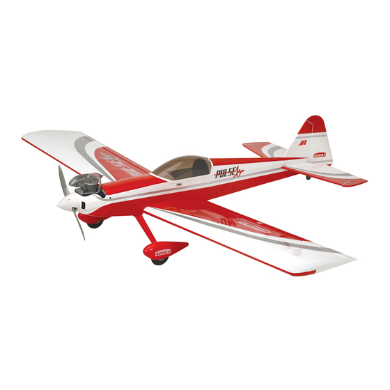
Pulse 125 ARF
Assembly Manual
Specifications
Wingspan ............................................................... 76.0 in (193 cm)
Length.................................................................... 62.5 in (159 cm)
Wing Area ..................................................1050 sq in (68.0 sq dm)
Weight .......................................................... 8.2–9.5 lb (3.7–4.3 kg)
Engine Size ........................... .61–1.20 2-stroke; .90–1.25 4-stroke
Motor Size ...............................90–110 brushless outrunner Motor
Radio ......... 4-channels or more w/5 servos (4 w/electric option)
Advertisement
Table of Contents

Related Manuals for Hangar 9 Pulse 125


Summary of Contents for Hangar 9 Pulse 125
- Page 1 Pulse 125 ARF Assembly Manual Specifications Wingspan ............... 76.0 in (193 cm) Length..............62.5 in (159 cm) Wing Area ..........1050 sq in (68.0 sq dm) Weight ............8.2–9.5 lb (3.7–4.3 kg) Engine Size ......61–1.20 2-stroke; .90–1.25 4-stroke Motor Size .......90–110 brushless outrunner Motor...
-
Page 2: Table Of Contents
Warranty Information ............36 HAN517015 Fuel Tank CE Compliance Information for the European Union ..37 HAN517017 Tailwheel Assembly 2009 Official Academy of HAN517018 Wing Bolt Plate Model Aeronautics Safety Code ........38 Engine Mounting Template ..........39 Hangar 9 Pulse 125 ARF Assembly Manual... -
Page 3: Included Parts Listing
3mm x 70mm aluminum tube Brass pushrod connector with backplate Throttle Rubber stopper Silicon clevis keeper Plywood firewall template Self-tapping screw Silicon tube Nylon stopper piece 10mm x 10mm x 110mm tank brace Hangar 9 Pulse 125 ARF Assembly Manual... -
Page 4: Using The Manual
120NX Engine (EVOE1200) ® This manual is divided into sections to help make assembly The Pulse 125 ARF requires a minimum of a 4-channel radio • Evolution Propeller 15 x 6 (EVO15060) easier to understand, and to provide breaks between each to operate the functions of your aircraft. -
Page 5: Additional Required Tools
• Pliers available on FS One such as the T-REX, Blade CX2, Blade CP 30-minute epoxy Mixing stick Pro, Hangar 9 P-51 and F-22 PTS. And as always, with the • Rubbing alcohol • Side cutter Mixing cup Medium grit sandpaper Hangar Pack, you still get all the same great features that •... - Page 6 Allow the CA to cure WITHOUT hole in the rudder. using accelerator as this will not allow the CA to wick full into the hinge. Continue once the CA and epoxy have both cured. Hangar 9 Pulse 125 ARF Assembly Manual...
-
Page 7: Tail Installation
The last step is to break in the hinges. Move the rudder through its range of movement a few times until it moves freely. Step 3 When installed, the fin will fit tight against the stabilizer. Hangar 9 Pulse 125 ARF Assembly Manual... -
Page 8: Radio Installation
Do not over-tighten the nuts and damage the fuselage. The nuts only need to be tightened enough so the stabilizer and fin are secure and do not move on the fuselage. Hangar 9 Pulse 125 ARF Assembly Manual... - Page 9 Step 9 choose the correct one for your application. Remove the clevises and nuts from the 27.5-inch (698mm) and 28.5-inch (724mm) linkage wires. Set the hardware aside so it doesn’t get lost. Hangar 9 Pulse 125 ARF Assembly Manual...
- Page 10 9/16-inch (15mm) from the center of the servo Step 13 horn for the pushrod wires. Insert the Z-bend from the 28 -inch (724mm) pushod in the hole enlarged earlier. Hangar 9 Pulse 125 ARF Assembly Manual...
-
Page 11: Aileron Servo Installation
Step 1 clevis to keep it from popping loose in flight. Secure a 9-inch (228mm) servo extension to the aileron servo. important: Make sure to use threadlock on all metal- to-metal fasteners. Hangar 9 Pulse 125 ARF Assembly Manual... - Page 12 Use a pin drill and 5/32-inch (2mm) drill bit to enlarge the hole that is 9/16-inch (15mm) from the center of the servo horn for the pushrod wire. Hangar 9 Pulse 125 ARF Assembly Manual...
-
Page 13: Landing Gear And Wheel Installation
Use 30-minute epoxy to glue the wing dowel in the leading edge of the wing. Remove any excess epoxy using a paper towel soaked in rubbing alcohol. Step 12 Repeat Steps 1 through 12 to prepare the opposite wing panel. Hangar 9 Pulse 125 ARF Assembly Manual... - Page 14 Make sure the collar is not too tight against the wheel by making sure the wheel can rotate freely on the axle. Hint: Place a drop of machine oil on the axle so the wheel will roll freely. Hangar 9 Pulse 125 ARF Assembly Manual...
-
Page 15: Four-Stroke Engine Installation
Always use threadlock on metal-to-metal fasteners to prevent them from vibrating loose. Step 8 Repeat Steps 2 through 7 to install the remaining wheel and wheel pant. Hangar 9 Pulse 125 ARF Assembly Manual... - Page 16 Step 4 Use four 4mm x 25mm socket head screws and four 4mm washers to secure the nylon mounts to the firewall. Note the positioning of the mounts as shown in the photos. Hangar 9 Pulse 125 ARF Assembly Manual...
- Page 17 Use a pin drill and 1/16-inch (1.5mm) drill bit to enlarge the center hole of the carburetor arm. Hint: It is suggested to use a drill press to drill these holes. This will guarantee they are aligned straight in the mount. Hangar 9 Pulse 125 ARF Assembly Manual...
- Page 18 Step 15 Place 2–3 drops of thin CA in each hole to harden the surrounding wood. This harder surface will make the screws less likely to vibrate loose. Hangar 9 Pulse 125 ARF Assembly Manual...
-
Page 19: Two-Stroke Engine Installation
Lift the hatch up at the rear and remove it from the fuselage. note: Always use threadlock on metal-to-metal fasteners to prevent them from vibrating loose. Hangar 9 Pulse 125 ARF Assembly Manual... - Page 20 Step 4 Use four 4mm x 25mm socket head screws and four 4mm washers to secure the nylon mounts to the firewall. Note the positioning of the mounts as shown in the photos. Hangar 9 Pulse 125 ARF Assembly Manual...
- Page 21 This will cut the threads for the screws in preparation of the next step. Hint: It is suggested to use a drill press to drill these holes. This will guarantee they are aligned straight in the mount. Hangar 9 Pulse 125 ARF Assembly Manual...
- Page 22 Use side cutters to remove any excess arms from the servo hardware, secure it in the radio tray using the screws horn so they don’t interfere with the operation of the throttle. provided with the servo. Hangar 9 Pulse 125 ARF Assembly Manual...
-
Page 23: Fuel Tank Installation
Always use threadlock on metal-to-metal fasteners to prevent them from vibrating loose. note: The stopper supplied is compatible with both gas and nitromethane fuels. Hangar 9 Pulse 125 ARF Assembly Manual... - Page 24 (6mm) from the back of the tank. If the clunk does not move freely you may experience fuel draw problems. Remove the stopper and shorten the fuel tube slightly; check and repeat until it can move freely inside the tank. Hangar 9 Pulse 125 ARF Assembly Manual...
-
Page 25: Cowling And Spinner Installation - Four-Stroke Engine
A piece of foam on the brace will help wires should face up and down for the best reception of your This will be the template for trimming your cowling. hold the tank securely. radio system. Hangar 9 Pulse 125 ARF Assembly Manual... - Page 26 Take your time trimming the cowl to achieve the best fit. Use a rotary tool and sanding drum to smooth any rough edges around the engine. Hangar 9 Pulse 125 ARF Assembly Manual...
-
Page 27: Cowling And Spinner Installation - Two-Stroke Engine
Cut a piece of cardstock to fit around the engine as shown. Step 9 template on the cowl. This will be the template for trimming your cowling. Secure the spinner cone to the backplate using two 3mm x 10mm self-tapping screws. Hangar 9 Pulse 125 ARF Assembly Manual... - Page 28 Secure the spinner cone to the backplate using two 3mm x trimming the cowl to achieve the best fit. Use a rotary tool 10mm self-tapping screws. and sanding drum to smooth any rough edges around the engine. Hangar 9 Pulse 125 ARF Assembly Manual...
-
Page 29: Electric Motor Installation
Use a installed for the best reception. covering iron to seal the edges around the opening so the covering does not come loose. Hangar 9 Pulse 125 ARF Assembly Manual... - Page 30 Remove the template and use a 5/32-inch (4mm) drill bit to enlarge the four holes drilled in the previous step. Step 8 Prepare the motor by installing the X-mount and propeller adapter. Hangar 9 Pulse 125 ARF Assembly Manual...
-
Page 31: Cowling And Spinner Installation - Electric Motor
The motor batteries can now be placed in the fuselage. Use a hook and loop strap (not included) to secure the batteries. Hook and loop tape can be placed between the batteries and battery tray to keep them from sliding in the fuselage. Hangar 9 Pulse 125 ARF Assembly Manual... -
Page 32: Final Assembly
Secure the spinner cone to the backplate using two 3mm x 10mm self-tapping screws. Step 5 Slide the propeller on the propeller adapter. The small standoffs on the spinner backplate will help in aligning the propeller. Hangar 9 Pulse 125 ARF Assembly Manual... - Page 33 Secure the wing to the fuselage using two 6mm x 40mm Slide the remaining wing panel on the tube. The two panels forward so the wing dowels go into the hole in the fuselage. nylon wing bolts. will fit tightly together. Hangar 9 Pulse 125 ARF Assembly Manual...
-
Page 34: Center Of Gravity
Travel Adjust, Sub-Trim and Dual Rates are not listed and should be adjusted according to each individual model and preference. After the first flights, the CG position can be adjusted for your personal preference. Hangar 9 Pulse 125 ARF Assembly Manual... -
Page 35: Flight Preparations
Check that all trim levers are in the proper location. Step 7 All servo pigtails and switch harness plugs should be secured in the receiver. Make sure that the switch harness moves freely in both directions. Hangar 9 Pulse 125 ARF Assembly Manual... -
Page 36: Age Requirements
For questions or assistance, please by Purchaser must be approved in writing by Horizon before direct your email to productsupport@horizonhobby.com, or shipment. call 877.504.0233 toll free to speak to a service technician. Hangar 9 Pulse 125 ARF Assembly Manual... -
Page 37: Ce Compliance Information For The European Union
Please note: Please call +49 4121 46199 66 or e-mail us at service@ non-warranty repair is only available on electronics and horizonhobby.de with any questions or concerns regarding model engines. this product or warranty. Hangar 9 Pulse 125 ARF Assembly Manual... -
Page 38: 2009 Official Academy Of Model Aeronautics Safety Code
Model Rocketry Safety Code; however, they may not be launched from model aircraft. Officially designated AMAAir Show Teams (AST) are authorized to use devices and practices as defined within the Air Show Advisory Committee Document. Hangar 9 Pulse 125 ARF Assembly Manual... -
Page 39: Engine Mounting Template
Engine Mounting Template SAITO 1.25 EVOLUTION 1.20 E-FLITE POWER 110 3.69-inch (91.73mm) Hangar 9 Pulse 125 ARF Assembly Manual... - Page 40 © 2009 Horizon Hobby, Inc. 4105 Fieldstone Road Champaign, Illinois 61822 (877) 504-0233 horizonhobby.com Hangar-9.com 15369 Printed 07/09...
Need help?
Do you have a question about the Pulse 125 and is the answer not in the manual?
Questions and answers