Table of Contents
Advertisement
TM
®
WE GET PEOPLE FLYING
46%
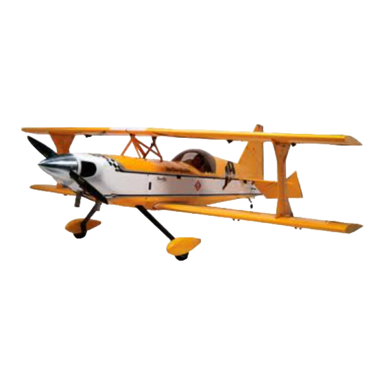
TOC Ultimate 10-300
ASSEMBLY MANUAL
Specifications
Wingspan ..........................................................................................100 in (2540 mm)
Length ................................................................................................110 in (2794 mm)
Wing Area.........................................................................................3310 sq in (213.5 sq dm)
Weight ...............................................................................................40–44 lb (18–20 kg)
Engine.................................................................................................150–200cc gas engine
Radio ..................................................................................................6-channel w/15 servos
Advertisement
Table of Contents

Related Manuals for Hangar 9 46% TOC Ultimate 10-300


Summary of Contents for Hangar 9 46% TOC Ultimate 10-300
- Page 1 ® WE GET PEOPLE FLYING TOC Ultimate 10-300 ASSEMBLY MANUAL Specifications Wingspan ..................100 in (2540 mm) Length ....................110 in (2794 mm) Wing Area..................3310 sq in (213.5 sq dm) Weight ....................40–44 lb (18–20 kg) Engine....................150–200cc gas engine Radio ....................6-channel w/15 servos...
-
Page 2: Additional Required Equipment
In the prototype models, we used JR 8411 ® digital servos with excellent results. A less powerful servo can lead to a crash. The Hangar 9 TOC Ultimate does not include hardware. Many experienced giant-scale pilots have specific hardware preferences and can individually choose the components they prefer. -
Page 3: Table Of Contents
Table of Contents Additional Required Equipment ........... . 2 Introduction . -
Page 4: Warning
Contents of Kit A. HAN1101 Fuselage w/Hatch K. HAN1111 Canopy Hatch B. HAN1102 Right TOP Wing w/Aileron L. HAN1112 Painted Fiberglass Cowl C. HAN1103 Left TOP Wing w/Aileron M. HAN1113 Fiberglass Wheel Pant Set D. HAN1104 Right BOTTOM Wing w/Ailerons N. -
Page 5: Other Items Needed (Not Included In The Kit)
• 6" Ultimate Spinner • Aileron Servo Arm (HAN3574) (8) • Throttle Servo Arm (HAN3531) • 4 " Hangar 9 Pro-Lite Wheels (HAN309) • 4-40 x 3 " Titanium Pro-Link (HAN3554) (10) • 1 " Hangar 9 Pro-Lite Wheel (HAN300) •... -
Page 6: Warranty Information
Before Starting Assembly Before beginning the assembly of the Ultimate, remove each part from its bag for inspection. Closely inspect the fuselage, wing panels, rudder, and stabilizer for damage. If you find any damaged or missing parts, contact Horizon Product Support. If any wrinkles in the covering, use a heat gun and covering iron to remove them. -
Page 7: Section 1: Aileron Servo Installation
All servos will have a slightly • Bottom wing panels (left and right) different neutral. If you are using Hangar 9 metal arms, • 24" Aileron Extensions (JRPA102) (4) they don’t always orient the same, (i.e. the splines are not •... - Page 8 Section 1: Aileron Servo Installation Note: It is always a good idea to secure the Step 5 servo connector and servo extension together Insert the servo with the 24" extension towards the tip to prevent the wires from becoming unplugged of the wing.
-
Page 9: Section 2: Temporary Hinging Of The Ailerons
Section 2: Temporary Hinging of the Ailerons Required Parts Step 3 • Hinges (16) • Top wing panel (2) Temporarily install all the hinges in the aileron. Check the fit of the hinges between the wing and aileron. • Bottom wing panel (2) • Top aileron (2) Make sure the gap is as close as possible while making •... -
Page 10: Section 3: Aileron Control Horn Installation
Section 3: Aileron Control Horn Installation Required Parts Step 2 • Control horn screws (4)• Control horn nuts (4) Mark the location for the aileron control horn. The horn is positioned as shown. Required Tools and Adhesives • Hobby knife •... - Page 11 Section 3: Aileron Control Horn Installation Step 3 Step 4 Remove the aileron from the wing panel. Drill a 5/32" Tap the hole for the screw using an 8-32 tap. hole perpendicular to the work surface in the location marked for the aileron control horn. The top of the aileron will be resting flat on the work surface.
- Page 12 Section 3: Aileron Control Horn Installation Step 6 Step 7 Remove the screw, then use a hobby knife, counter sink Once the aileron has been counter-sunk, thread bit, or 5/16” drill bit to taper the hole. This is done to the screw back into the aileron.
-
Page 13: Section 4: Gluing The Aileron Hinges
Photo for Step 1 Super Hinge Points in all giant-scale aircraft. They are easy to install, very strong and offer ® smooth friction-free control. The Hangar 9 Ultimate control surfaces are predrilled to use Robart Super Hinge Points (ROB309). Step 1 Mix 1 ounce of 30-minute epoxy. - Page 14 Section 4: Gluing the Aileron Hinges Note: Be sure that the hinge pivot pins are Step 3 parallel and flush to the trailing edge. It’s Carefully slide the aileron onto the wing. Remove any important to frequently mix a fresh batch of excess epoxy using a paper towel and Denatured alcohol.
-
Page 15: Section 5: Aileron Linkage Installation
Pro-Link to lengthen or shorten the linkage. Hangar 9 also offers a Pro-Link Wrench (HAN3558) to make adjustments easier. - Page 16 Section 5: Aileron Linkage Installation Step 3 Step 7 Attach the linkage to the swivel horn on the inboard servo Deflect the ailerons stick to full right and hold it there. only with the bolt supplied. Adjust the linkage length until The easiest way is to have your transmitter set to PCM: the hole in the ball link aligns with the outer hole in the hold and then turn off the transmitter.
-
Page 17: Section 6: Hinging The Elevators
Section 6: Hinging the Elevators Required Parts • Hinges (6) • Elevator (2) • Stabilizer Required Tools and Adhesives • 30-minute epoxy • Toothpicks or small dowel • Small brush • Masking tape • Felt-tipped pen • Ruler • Razor saw •... - Page 18 Section 6: Hinging the Elevators Step 4 Install the hinges in the stabilizer. Photo for Step 6 Step 7 Check the fit between the stabilizer and elevator. Adjust the slots in the stabilizer if necessary. Once the fit is Step 5 satisfactory, mix 1/2 ounce of 30-minute epoxy and join Slide the elevators into position against the stabilizer.
- Page 19 Section 6: Hinging the Elevators Step 8 Step 11 Clean up any excess epoxy using a paper towel and Cut the tapered portion off the tip of a round toothpick. denatured alcohol. Place the toothpick (or small dowel) into the holes drilled. Use a razor saw to trim the excess flush with the elevator and stabilizer.
-
Page 20: Section 7: Hinging The Rudder
Section 7: Hinging the Rudder Required Parts • Hinges (5) • Rudder • Fin Required Tools and Adhesives • 30-minute epoxy • Toothpicks or small dowel • Small brush • Masking tape • Felt-tipped pen • Ruler • Razor saw •... - Page 21 Section 7: Hinging the Rudder Step 4 Scuff the hinges using sandpaper. Mix 1/2 ounce of 30- minute epoxy and glue the hinges into the rudder. Clean up any excess epoxy using a paper towel and Denatured alcohol. Allow the epoxy to fully cure before continuing to the next step.
-
Page 22: Section 8: Sealing The Hinge Gap
Section 8: Sealing the Hinge Gap Required Parts Step 3 • Covering (not included) Position the covering into the hinge gap. Use a covering iron and trim tool to iron the covering Required Tools and Adhesives down into the hinge gap of the ailerons. •... -
Page 23: Section 9: Elevator Control Horn Installation
Section 9: Elevator Control Horn Installation Required Parts Step 2 • Control horn screws (2)• Control horn nuts (2) Use a 5/32" drill bit to drill through the elevators. Again, use a drill press for the best results. Required Tools and Adhesives Important: Make sure to drill perpendicular •... -
Page 24: Section 10: Rudder Control Horn Installation
Section 9: Elevator Control Horn Installation Step 5 Step 6 Install the control horn screw into the elevator. Thread a control horn nut down onto the horn and against the elevator. Use a drop of threadlocking compound to keep the nut from vibrating loose during flight. - Page 25 Section 10: Rudder Control Horn Installation Step 2 Step 5 Use a 5/32" drill bit to drill through the rudder. A Thread the control horn standoff nuts onto the drill press will ensure the hole is perpendicular to threaded rods. Use a drop of threadlocking compound the rudder.
-
Page 26: Section 11: Mounting The Horizontal Stabilizer
Section 11: Mounting the Horizontal Stabilizer Required Parts Step 2 • Fuselage • 6-32 blind nuts (4) Measure and mark a centerline on the stabilizer base on the fuselage. • 6-32 x 1" socket head bolts (4) • Horizontal stabilizer assembly •... - Page 27 Section 11: Mounting the Horizontal Stabilizer Step 5 Step 6 Position the stabilizer on the stabilizer base. Use Measure from the tip of the stab on right to the right wing the centerline on the base and stab to aid in positioning. tip and record the distance.
- Page 28 Section 11: Mounting the Horizontal Stabilizer Step 8 Step 10 Remove the stabilizer and re-drill the holes in the Apply a few drops of thick CA to each blind nut. Use stabilizer mounting flanges using an 11/64" drill bit. accelerator to cure the CA. Be careful not to get CA Place a piece of plywood under the flange to prevent the into the threads.
-
Page 29: Section 12: Mounting The Vertical Stabilizer
Section 12: Mounting the Vertical Stabilizer Required Parts Step 2 • Vertical stabilizer assembly • Fuselage Measure the distance the dowels extend out of the fin. This distance should measure 1". • #2 x 1/2" sheet metal screws (2) • 1/4" x 1 "... - Page 30 Section 12: Mounting the Vertical Stabilizer Step 4 Step 6 Locate the two remaining dowels and test fit them With the fin fairing installed, position the dowels so they into the fin as shown. protrude 3/4" from the fin fairing. Mark the dowels at the edge of the fairing using a felt-tipped pen.
- Page 31 Section 12: Mounting the Vertical Stabilizer Step 9 Step 10 Mix 1 ounce of 30-minute epoxy and lightly apply Test fit the fin onto the fuselage. Make adjustments the epoxy to the inside edge of the fairing and the to the holes in the fuselage to allow the fin to slide front edge of the fin.
- Page 32 Section 12: Mounting the Vertical Stabilizer Step 12 Step 14 Slide the fin back onto the fuselage. Align the ruler Drill two 1/16" holes at the locations marked in on the lines drawn on the rudder. Extend the two the previous step. These holes do not need to lines onto the fuselage.
-
Page 33: Section 13: Elevator Servo Installation
Section 13: Elevator Servo Installation Required Parts Step 3 • Fuselage assembly Install the linkage as shown. The bottom of the clevis will be positioned 1 ” from the elevator to provide the • 4-40 x 3 " Pro-Links (HAN3554) (2) recommended amount of control throw. -
Page 34: Section 14: Rudder Servo Installation
Section 14: Rudder Servo Installation Required Parts Step 3 • Fuselage assembly Mount the servo tray into the fuselage. Make sure it is secure, and will not move during the operation • Pull-pull cable • Cable crimps (4) of the rudder. •... -
Page 35: Section 15: Tail Wire Bracing Installation
Section 14: Rudder Servo Installation Step 6 Install the ball ends, crimps, and couplers on both the rudder end and servo end of the cable. To achieve proper geometry the cables must criss-cross in the fuselage. Attach and adjust the cables, removing the slack. It is highly suggested to use a crimping tool to install the crimps. - Page 36 Section 15: Tail Wire Bracing Installation Step 2 Step 3 Locate the holes in the stabilizer and fin for the Position the rigging attachments on the fin and rigging attachments. There will be two holes in the stabilizer. It will be necessary to add a slight bend to fin, and two holes in the left and right sides of the the attachments as shown.
- Page 37 Section 15: Tail Wire Bracing Installation Step 4 Step 6 Secure the rigging attachments using 4-40 x 3/4" socket Secure the rigging to the lower attachment tabs by head screws and 4-40 lock nuts. Tighten the nuts, but do threading the cable through the tab as shown. Use crimps not crush the underlying wood when tightening.
- Page 38 Section 15: Tail Wire Bracing Installation Step 7 Step 8 Use the same technique from the previous step to Use rigging couplers, crimps, nuts and clevises to attach the cables to the rigging attachments on the complete the rigging installation. Adjust the clevises top of the stabilizer.
-
Page 39: Section 16: Tail Wheel Installation
Section 16: Tail Wheel Installation Required Parts Step 2 Make a steering plate using scrap 1/8" plywood. Secure • Fuselage assembly • 1 " tail wheel the plate to the bottom of the rudder using • 1/8" wheel collar w/set screw (2) two #2 x 1/2"... -
Page 40: Section 17: Main Landing Gear Installation
Section 17: Main Landing Gear Installation Required Parts Step 3 • Fuselage assembly • 10-32 lock nut (4) Remove the gear and drill the location of the bolt using a 3/16" drill bit. • #10 washer (4) • Landing gear •... - Page 41 Section 17: Main Landing Gear Installation Step 5 Step 7 Remove the gear. Mark the aluminum gear support plates Bolt the plates back into the fuselage using their so they can be returned to their original locations. original hardware. Attach the landing gear using four Remove the plates and sand the two surfaces that rest 10-32 x 1 "...
-
Page 42: Section 18: Wheel Pant Installation
Section 18: Wheel Pant Installation Required Parts Step 3 Measure and mark the location for the axle on the • Fuselage assembly • 4 " main wheel (2) wheel pant. The center of the axle will be located • 4-40 blind nut (4) •... - Page 43 Section 18: Wheel Pant Installation Step 5 Step 7 Use a 1/8" drill bit to drill the two holes for the Insert two 4-40 blind nuts from the inside of the wheel wheel pant mounting screws. pant. Use thick CA to secure the position of the nuts. Use care not to get CA into the threads of the nuts.
-
Page 44: Section 19: Cabane Strut Installation
Section 18: Wheel Pant Installation Step 8 Install the wheel pant and wheel. Use two 4-40 x 1/2" socket head screws and two #4 washer to secure the wheel pant position. Use two 3/16" wheel collars to keep the wheel on the axle. Photo for Step 8 Note: Adjust the wheel collars so the wheel is centered side-to-side in the wheel pant. - Page 45 Section 19: Cabane Strut Installation Step 3 Step 5 Slide the cabanes into position. The front cabane Install the cross braces. The end with the twist is only has holes at the top and bottom, while the rear positioned at the top of the forward cabane. Secure the has a hole near the top of the fuselage.
-
Page 46: Section 20: Interplane Strut Installation
Section 20: Interplane Strut Installation Required Parts Step 2 • Wing assembly • #4 washer (8) Secure the attachments using 4-40 x 1/2" socket head screws and #4 washer from the opposite side • 4-40 x 1/2” socket head bolts (8) of the wing. -
Page 47: Section 21: Bottom Wing Installation
Section 21: Bottom Wing Installation Required Parts Step 2 • Bottom wing assembly • Fuselage assembly Mix 1/2 ounce of 30-minute epoxy and apply it to a 1/4-20 blind nut. Insert the blind nut into the wing • Wing tube •... -
Page 48: Section 22: Top Wing Installation
Section 21: Bottom Wing Installation Step 3 Slide the wing into position. Make sure the wing rests flush with the fuselage. Secure each wing panel using a 1/4-20 x 2 nylon bolt. Photo for Step 3 Section 22: Top Wing Installation Required Parts •... - Page 49 Section 22: Top Wing Installation Step 2 Step 4 Slide the tube into one of the top wing halves. Slide the remaining top wing panel onto the tube and against the center rib. Step 3 Slide the wing panel into position. The panel will rest flush against the center rib wing installed correctly.
-
Page 50: Section 23: Interplane Strut Installation
Section 23: Interplane Strut Installation Required Parts Step 2 • Interplane strut (2) • 6-32 blind nut (8) Place on strut into position. Make sure the curves on the strut follow the airfoil of the wings. The strut • #6 nylon washer (8) attachments will be hidden inside the struts. - Page 51 Section 23: Interplane Strut Installation Step 3 Step 4 Install the remaining strut. Note that after the cabane rib is Place a #6 washer onto a 6-32 x 1" screw. Slide the screw installed you will need to apply some pressure to separate through the strut and strut attachment.
-
Page 52: Section 24: Setting The Incidence
Section 24: Setting the Incidence Required Parts Step 2 • #8 washer (2) • 8-32 lock nuts (2) Mark centerlines on the leading edge of the top and bottom wings. Make a set of marks near the fuselage, • Carbon center rib and a set near the Interplane struts. - Page 53 Section 24: Setting the Incidence Step 4 Place an incidence meter on the bottom wing near the fuselage. Adjust the angle of the fuselage until the meter reads “0.” Block the fuselage so it will remain at this angle for the remainder of this section. Step 5 Measure and record the incidence of the top wing.
-
Page 54: Section 25: Engine Box Preparation
Section 24: Setting the Incidence Step 9 Step 11 Drill a hole in the wing tube using a #44 drill bit. Drill Secure the tube using a 4-40 x 1/2" screw and only through the top side of the tube. #4 washer. - Page 55 Section 25: Engine Box Preparation Step 3 Photo for Step 1 Use a razor saw to cut the excess dowel. Step 2 Cut a 1/8" dowel into twelve 1" lengths. Apply 30-minute epoxy to one end of the dowel piece and into one hole.
-
Page 56: Section 26: Mounting The Engine
Section 26: Mounting the Engine Required Parts Step 2 • Fuselage assembly • Engine Draw a vertical and horizontal centerline on the firewall. The horizontal line is located 2 " from • 1/4-20 blind nuts (4) the top of the firewall, and the vertical line 3 "... - Page 57 Section 26: Mounting the Engine Step 5 Mount the engine using four 1/4-20 x 1" socket head bolts and four 1/4-20 blind nuts. Apply thick CA to the back of the blind nut to hold it in position. Photo for Step 3 Step 4 Remove the clamps holding the engine and set the engine aside.
- Page 58 Section 26: Mounting the Engine Note: If you are using a DA150, the location Step 9 for the servo is 2" back from the firewall and Locate the 1/4" plywood engine box cover. Test fit " from the left side of the engine box. the cover onto the engine box.
-
Page 59: Section 27: Mounting The Cowling
Section 26: Mounting the Engine Step 10 Step 11 Mix 1 ounce of 30-minute epoxy. Apply the epoxy to top Once the epoxy has fully cured,use finishing resin and edge of the engine box. Place the engine box cover onto fuel-proof any exposed bare wood. -
Page 60: Section 28: Mounting The Canopy
Section 28: Mounting the Canopy Required Parts Step 4 • Fuselage assembly • Canopy Lightly sand the inside edge of the canopy and slightly inside the line drawn on the hatch using • 40% Pilot Figure • Instrument panel medium sandpaper. Required Tools and Adhesives •... - Page 61 Section 28: Mounting the Canopy Step 5 Photo for Step 5 Apply a bead of RCZ56 Canopy Glue (ZINJ5007) around the inside edge of the canopy. Position the canopy onto the hatch. Use tape to hold the canopy secure until the glue fully cures.
-
Page 62: Section 29: Final Radio Installation
Section 29: Final Radio Installation Required Parts Step 2 • Fuselage assembly Cut a hole in the bottom of the top wing panels for the servo leads to pass through. The hole is located • Top wing assembly " forward of the trailing edge and 1/4" from Required Tools and Adhesives the root of the wing. -
Page 63: Adjusting The Engine
Control Throws and Center of Gravity Recommended CG Location The following control throws offer a good place to start with your first flights. We recommend only one rate An important part of preparing the aircraft for flight is setting for the Ultimate. As you become more familiar properly balancing the model. -
Page 64: Setup And Flight Information By Mike Mcconville
Setup and Flight Information by Mike McConville Our new 46% Ultimate 10-300 is a truly extraordinary While many smaller models are very tolerant of model that has been developed over the past 10 years. improper control linkage setups and flying techniques, Originally developed for the 1994 Tournament of large models are not. - Page 65 Setup and Flight Information by Mike McConville The Prototype Model Setup Computer Radio Enhancements All of the recommended settings in this manual are a A computer radio will allow quite a bit of fine-tuning of result of the flight-testing on the prototype Ultimates. the feel of the Ultimate, making aerobatics even easier.
- Page 66 Setup and Flight Information by Mike McConville Rates and Expos: When and Where to Use Them Unloading Snaps I Always use expo to soften the feel of the model. On To start a snap roll, the same method as with a smaller high 3D rates, I use quite a bit.
- Page 67 Setup and Flight Information by Mike McConville The Maneuvers • The Elevator Let’s cover the seven 3D maneuvers where the Ultimate What it is: The plane drops vertically while in a nose really excels. high attitude. Depending on the head wind conditions, the model will drop anywhere from about a 45°...
- Page 68 Setup and Flight Information by Mike McConville • The Harrier • The Torque Roll What it is: It is very slow forward flight in a very nose This is one of the Ultimates 3D specialties. high (about 45°) attitude. What it is: The Ultimate “hovers” vertically in place, Setup: Same as the Elevator, and the raised ailerons rotating left around its roll axis.
-
Page 69: 2003 Official Ama National Model Aircraft Safety Code
2003 Official AMA National Model Aircraft Safety Code GENERAL 7) I will not operate models with pyrotechnics (any device that explodes, burns, or propels a projectile of any kind) 1) I will not fly my model aircraft in sanctioned events, air including, but not limited to, rockets, explosive bombs shows or model flying demonstrations until it has been dropped from models, smoke bombs, all explosive gases... - Page 70 2003 Official AMA National Model Aircraft Safety Code Continued 4) I will operate my model using only radio control Organized R/C Racing Event frequencies currently allowed by the Federal 10) An R/C racing event, whether or not an AMA Rule Communications Commission.
- Page 71 Hangar 9 accessories are designed specifically to meet the demands of top-level models such as the Hangar 9 Ultimate. Giant Scale Precision Control Horns (HAN3614, HAN3615) HD Ball Links (HAN3616, HAN3617, HAN3618) • Strong and durable • Ideal for hi stress giant scale models...
- Page 72 ¤ © 2003, Horizon Hobby, Inc. 4105 Fieldstone Road Champaign, Illinois 61822 (217) 355-9511 www.horizonhobby.com # 5833...
Need help?
Do you have a question about the 46% TOC Ultimate 10-300 and is the answer not in the manual?
Questions and answers