
Related Manuals for Mountain Models Little Bogie


Summary of Contents for Mountain Models Little Bogie
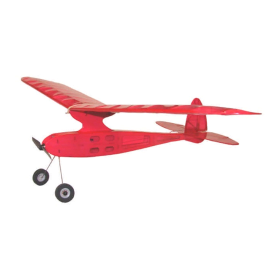
- Page 1 Little Bogie™ Mini Old Timer Electric Model Little Bogie™ Specifications Wingspan: 36.0 in. Length: 19.4 in. Wing Area: 164 sq. in. Weight (Ready to Fly): 4.2 to 4.5 oz. Wing Loading: 3.7 – 4.0 oz. / sq. ft. Version 1.0, April 4, 2010...
-
Page 2: Warranty
Although not needed for building, full size plans are included for reference. If the instructions are read before hand and followed during the build, the Little Bogie™ can be built up and ready to fly in only a few evenings. -
Page 3: Before You Begin
Before You Begin Check to make sure that all of your parts are there and in good shape. Parts List Number Description of Part in Kit Bundled Parts Laser Cut Parts (See wood inventory sheet) Plan Sheet (24” x 36”) These instructions of course! Metal (on the back of the wood bundle) 0.025”... -
Page 4: Electronics You Will Need
Electronics You Will Need • 3 channel radio minimum • 4 channel mini receiver (Berg 4L or Spektrum 6110e) • 2 ea. 3.7 gram servos (Power HD 1370A or Mountain Models 3.7) • D1811-2000 10 gram Outrunner • GWS 6030 HD Prop •... - Page 5 WOOD INVENTORY SHEET...
- Page 6 STEP 1: Bend the landing gear, as shown on the plan sheet. It has already been bent to shape, but you must still add the second bend, so the landing gear legs are bent forward. STEP 2: Fasten the landing gear to the "...
- Page 7 STEP 5: Test fit the pylon into the fuselage top sheet. Sand the sides of the pylon, if necessary, so it fits through the slot smoothly. STEP 6: Now is the best time to cover the pylon. Covering the pylon AFTER assembly is much harder to do, though it is still possible.
- Page 8 STEP 8: Press the 3/32" balsa F2 onto the crutch/pylon assembly (with the engraved text to the FRONT) and press the firewall onto the crutch/pylon assembly. (with the engraved text to the front) Do NOT glue them together yet.
- Page 9 STEP 9: Press the 1/16" balsa sides onto the pylon/crutch assembly. Holding everything together, making SURE that all parts are fully pressed into place, secure all joints with some thin CA. Do NOT glue the fuselage sides together at the rear. STEP 10: Press the 1/16"...
- Page 10 STEP 11: Slide the 1/16" balsa fuselage top over the crutch and into place on all the formers and fuselage sides. Glue the top in place using thin CA. Press the 1/16" balsa F5A and F5B parts in place and secure them with thin STEP 12: Press the 1/16"...
- Page 11 STEP 13: Press the 1/16" balsa fuselage bottom in place and then remove the front hatch. AFTER removing the hatch, glue the fuselage bottom in place using thin CA. STEP 14: Glue the 1/16" balsa hatch onto the 1/16" balsa hatch braces, as shown. Use thick CA or a slower setting glue.
- Page 12 STEP 15: Laminate the 1/64" plywood trailing edge reinforcement part onto the 1/16" balsa W18A trailing edge part. It should be aligned with the trailing edge and the engraved line at the root area. Use a slower setting glue, such as thinned 5 minute epoxy or white glue, weigh the parts down to MAKE SURE that it is flat when the glue dries.
- Page 13 STEP 19: Slide the 1/16" balsa leading edge support parts, W15 and W16 in place in the ribs, as shown. Do NOT glue anything yet. STEP 20: Slide the 1/8" balsa leading edge in place over the leading edge support, as shown. Keep the wing FLAT and straight by using some weight of some kind.
- Page 14 STEP 23: Sand off the parts overhanging the wing root, so they are flush with the center rib, on each wing. Do NOT sand into the rib itself. Why did we make you build the wing in halves, instead of 1 piece? We did it so you could more easily modify it for a 2-piece wing if you desired to do so.
- Page 15 STEP 26: Protect the plans by laying down clear plastic wrap over them. Build the tails over the plans, using thin CA on all the joints. STEP 27: Lightly sand the tail parts. You can round the OUTSIDE edges of the parts if you'd like, for a nicer looking finished model.
- Page 16 STEP 29: Lightly finish sand all of the fuselage parts with 320 or 400 grit sandpaper. Rounding off the corners makes it look better when it's covered. Also remove the " plywood pylon parts and the " F6 part that are still in the parts sheets and sand them as well.
- Page 17 STEP 34: Remove any covering from the parts where they contact and will be glued to other parts, with a SHARP X-Acto blade, being careful not to cut into the wood itself. STEP 35: Glue the pylon parts together, using thick CA or a thin application of 5-minute epoxy.
- Page 18 STEP 40: Trim ONE of the plastic control horns as shown. This is for the elevator, so it clears the fuselage bottom. STEP 41: Glue the plastic control horns into the rudder and elevator, as shown. Hinge line STEP 42: Trim off the ends of the ribbed control horn post to be flush with the control surface.
- Page 19 STEP 43: Insert the elevator control horn through the hole in the fuselage top and slide it onto the elevator pushrod Z-bend. This can be a bit tricky, but take it slowly and you'll get it. Alternatively, you could pull the pushrod out through the hole with some needle nose pliers, hook up the elevator control horn, and then press it back into the fuselage.
- Page 20 TAPE Elevator at full deflection. STEP 46: Hinge the elevator to the stabilizer with tape. You can use average clear packing tape or Blenderm. Keep the elevator in the down position and straight while applying the tape, so you get a full range of movement once it's complete.
- Page 21 STEP 49: Remove the motor from the motor mount. Mount the motor mount to the firewall, using the included #2 screws. Make sure the set screw on the mount for securing the motor is facing up so you can reach it to reinstall the motor. STEP 50: Hook up the motor to the ESC (ESC was installed in step 30) and run the motor wires through the...
- Page 22 STEP 53: Set the control throws as follows: LOW RATES: Rudder: 3/8" (9.5 mm) left and right Elevator: 3/8" (9.5 mm) up and down HIGH RATES: Rudder: 1/2" (12.7 mm) left and right Elevator: 1/2" (12.7 mm) up and down STEP 54: Mount the battery in the fuselage with the double sided velcro, included in this kit, as shown on the plans.
Need help?
Do you have a question about the Little Bogie and is the answer not in the manual?
Questions and answers