
Related Manuals for Intercomp CW250


Summary of Contents for Intercomp CW250
- Page 1 CW250 Users Manual Intercomp Co. 3839 County Road 116 Medina, MN 55340, U.S.A. 763-476-2531 800-328-3336 Fax: 763-476-2613 www.intercompcompany.com Manual #: 700014 rev J...
-
Page 2: Table Of Contents
DIAGNOSTICS .................................27 CONNECTOR ................................28 HOW TO REACH INTERCOMP...........................29 "This document is the property of Intercomp Co. It contains material and information that is confidential and protected under federal and/or state trade secret, unfair competition, and copyright law. Any reproduction, use or disclosure without written permission from Intercomp Co. -
Page 3: Introduction
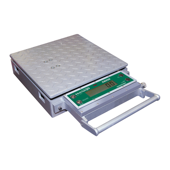
CW250, Users Rev J, October, 2010 Introduction This operations manual describes the Intercomp Model CW250 specifications, detailed operating procedures, and calibration. This manual is separated into several sections, each containing information on a different aspect of the platform. The specifications outline the design parameters for the scale. -
Page 4: Specifications
CW250, Users Rev J, October, 2010 Specifications Controls General On/Off, Print/Accumulate, Local/Total, Zero Display 5½ digit, 1 inch liquid crystal display (LCD), with automatic LED back lighting. Indicators: lb, kg, TOTAL, ERROR, ‘-‘ (minus) sign, and a 4 segment battery indicator. -
Page 5: Operations
The TOTAL icon indicates measurement mode as in the table below the CW250 display. Information displayed includes indicators for both “lb” and “kg”, a segment bar to show battery charge level, error conditions and set-point indicators when set-point thresholds are reached. -
Page 6: Controls
If a problem is detected, the screen displays an error message. If the CW250 is powered up, press this button to turn the scale off. The CW250 retains the setup information, and calibration in a special memory device (non- volatile memory) that is not affected by power loss or battery condition. - Page 7 CW250, Users Rev J, October, 2010 wheel chocks. When the weight is removed, a negative weight displays until the system is re-zeroed. This switch is used any time the scale shows a non-zero value with no weight on the pads. Please note that this system contains a feature called Auto Zero Tracking (AZT), which corrects for slight zero changes during normal operation.
-
Page 8: Totalizing Setup
Rev J, October, 2010 Totalizing Setup The CW250 scales must be setup correctly in order to communicate. If the system is not setup correctly, the “error icon” and message “t0t “will be displayed when trying to view the total weight. - Page 9 CW250, Users Rev J, October, 2010 Note: The scale will not accumulate when the weight is negative, zero, or if the weight is in motion. These Protections are added to ensure that only valid readings are accumulated into the total. An error message “Ac.Err” will be displayed if any of those conditions are present.
-
Page 10: Serial Output Setup
Press PRINT/ACCUMULATE to print either the local or total weight (depending on the local/total setting of the scale). This is the default print mode. Continuous The CW250 automatically and continuously outputs the weight at a rate of about once per second. Page 10 of 29... -
Page 11: Data Format
CW250, Users Rev J, October, 2010 Data Format When the serial output is set to either on-demand or continuous mode, the transmitted data is in the format shown below: AAAAAAA BB<cr><lf> Item Meaning ASCII Hex ASCII Decimal AAAAAAA weight units “lb” or “kg”... -
Page 12: Using Accumulated Total
Rev J, October, 2010 Using Accumulated Total The CW250 platforms can be used separately, in pairs, or in groups to measure a support load or the total weight in one measuring procedure. To use the Accumulated Total feature, the scales need to be numbered correctly and the scale you intend to print from or display the accumulated total must have it’s print... -
Page 13: Accumulating Print Standard
CW250, Users Rev J, October, 2010 AC. 2 10110 39480 74520 Total number of Current local Total weight of Current total accumulations weight on this accumulations weight on all this session scale this session scales Note: The scale will not accumulate and will display the error message “Ac.Err”... -
Page 14: Accumulating Procedure
CW250, Users Rev J, October, 2010 AC. 3 1500 1500 3450 Total number of Current local Total weight of Current total accumulations weight on this accumulations weight on all this session scale this session scales Note: The scale will not accumulate and will display the error message “Ac.Err”... - Page 15 CW250, Users Rev J, October, 2010 if the scale is in the Accumulation Print mode. (TOTAL icon flashing). After accumulation, remove the first group of items from the scale(s). 3. With the next group of items stable on the scale(s), press the PRINT/ACCUMULATE button.
-
Page 16: Mode Menu
CW250, Users Rev J, October, 2010 Mode Menu Mode Menu To access the mode menu simultaneously press the PRINT/ACCUMULATE and ZERO buttons. The display will show “b.LitE”. If it doesn’t, go to Calibration Enable Jumper section and verify the scale is in the RUN position.(shorting pins 2 and 3(RUN) At times it will be necessary to enter up to a five digit number. -
Page 17: Setting The Mode Menu Parameters
CW250, Users Rev J, October, 2010 Setting the Mode Menu Parameters 1. Simultaneously press the PRINT/ACCUMULATE and ZERO buttons. The display will show “b.LitE”. Press the PRINT/ACCUMULATE button. The flashing display shows the current setting. Press the ZERO or the LOCAL/TOTAL buttons to toggle between Auto, on, and off. - Page 18 (maximum number of scales in this mode is 32) Current Loop is not used in the CW250. When scales are not part of a totalizing network, battery life will be improved if “nonE” is chosen. Use the LOCAL/TOTAL button or the ZERO button to cycle through the settings.
- Page 19 CW250, Users Rev J, October, 2010 14. The display will show “rF CH”. Press the PRINT/ACCUMULATE button. The flashing digit shows the current setting. All scales in a system must be set to the same radio channel setting in order to communicate with each other. Use the LOCAL/TOTAL button to increment and the ZERO button to move the number flashing to the left.
-
Page 20: Calibration
To access the calibration mode the shorting strap labeled “RUN/CAL”, located on the right-middle of the circuit board (Intercomp, A/D 20 BIT rev E), it must be moved from shorting pins 2 and 3(RUN); to shorting pins 1 and 2(CAL). To access the shorting strap, remove the 10 screws on the outside edges of the display assembly. -
Page 21: Calibration Menu
CW250, Users Rev J, October, 2010 Calibration menu To initiate calibration simultaneously press the PRINT/ACCUMULATE and ZERO buttons. The display will show “StEP”, if it does not, the calibration strap is incorrectly placed to allow calibration. Return to ‘Calibration Enable Jumper’ section to verify correct setting. -
Page 22: Setting The Calibration Parameters
PRINT/ACCUMULATE button. Multiple Graduation Break Points The CW250 has the ability to have multiple graduation values set. Following is an example of setting graduation break points. Example: Grad = Initial graduation equals by 0.1 lb... - Page 23 An entry of ‘1’ results in a reduced conversion time which extends battery life. For the CW250 it is recommended to leave this set to ‘1’. Note that if this setting is changed, the scale must be recalibrated. Use the LOCAL/TOTAL button to increment and the ZERO button to decrement the number.
-
Page 24: Weight Calibration
To calibrate with one point, simply turn off the scale after completing step 13 as listed below. To calibrate with two points, turn off the scale after completing step 15 as listed below. The CW250 has the capability to apply and load up to 10 calibration points. - Page 25 CW250, Users Rev J, October, 2010 18. The display shows “HH-04”. Press the PRINT/ACCUMULATE button. The display will show “00000” with the far right number flashing. Use the LOCAL/TOTAL button to advance the number and the ZERO button to move the number flashing to the left.
-
Page 26: Error Messages
CW250, Users Rev J, October, 2010 Error Messages Message Meaning EEPE EEPROM failure. Scale will require recalibration AD 1 AD converter failure. Circuit board may need to be repaired or replaced LCbxx Self test shunt-current circuitry has detected one or multiple load cell errors. -
Page 27: Diagnostics
The ‘step’ choice that starts the calibration menu also allows special codes for technical diagnostic work. Typically only scale technicians should use these features. Here is the list of possible entries to the ‘step’ choice related to the CW250: Message Meaning Simply advance to the first Calibration Menu step. -
Page 28: Connector
CW250, Users Rev J, October, 2010 Connector The diagram below shows the pin-out for the PT connector on the side of the CW250: PT connector A: RS-485 A B: TXD (RS232) C: - Charging Voltage D: none E: +Charging Voltage... -
Page 29: How To Reach Intercomp
CW250, Users Rev J, October, 2010 How to reach Intercomp Things to know: Inform the Service Dept. that the product is a CW250 scale. When was the scale purchased? Where was the scale purchased? What is the serial number? For Intercomp Service call or fax:...
Need help?
Do you have a question about the CW250 and is the answer not in the manual?
Questions and answers