
Related Manuals for Intercomp PW800


Summary of Contents for Intercomp PW800
- Page 1 PW800 Users Manual Intercomp Co. 3839 County Road 116 Medina, MN 55340 U.S.A. (763)-476-2531 1-800-328-3336 Fax: 763-476-2613 www.intercompcompany.com Manual #: 700016-O Page 1 of 25...
- Page 2 Failure to comply with these precautions or with specific warnings elsewhere in this manual violates safety standards of design, manufacture, and intended use of the scale. Intercomp assumes no liability for the customer's failure to comply with these requirements.
-
Page 3: Table Of Contents
COREBOARD CONTINUOUS HOW TO REACH INTERCOMP SERVICE......................25 "This document is the property of Intercomp Co. It contains material and information that is confidential and protected under federal and/or state trade secret, unfair competition, and copyright law. Any reproduction, use or... -
Page 4: Introduction
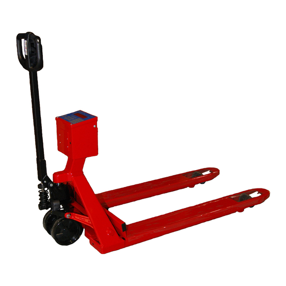
PW800, Users Rev O, January, 2008 Introduction This manual contains specifications, operation instructions, and calibration instructions for Intercomp's model PW800 pallet scale. Troubleshooting tips and a parts and accessories listing are also included. Specifications Controls Display: 0.8” 5 digit LED (Optional: 5 digit, 1.0 inch LCD) Indicators: On-screen lb, kg, pieces, gross, net, total, and peak. -
Page 5: Parts And Optional Equipment
RS232C Serial data output (100922) An RS232 output allows the user to connect the PW800 to a printer or computer. Battery operated tape printer (100921) Print ticket displays gross, net, tare, and total weights; and total count. Must have the RS232 Serial data output option. -
Page 6: Operations
PW800, Users Rev O, January, 2008 Operations Controls ON/OFF Press and hold this button 1 second to turn the scale on and off. The scale tests itself; when this test is completed successfully the system begins weighing. The product I.D. -
Page 7: Clear
NET/GROSS Toggles the readout between net weight and gross weight. Net weight applies only when there is a tare set. The indicator on the left side shows if the PW800 is displaying gross or net weight. Net = Gross – Tare Notes: The weight will always be net when in pieces unit. -
Page 8: Preset Tare
If you need to enter piece weights less than 1 lb or 1 kg, see the APW decimal position section in ‘Calibration’. This can setup your PW800 to record APW’s by tenths (1 decimal place) or by hundredths (2 decimal places). -
Page 9: Total
(set point) is reached, a logic level high will be on the set point connection. Set points are used with some other device (e.g. alarm, relay) in conjunction to the PW800. To activate a set point, press the Set Point 1 (or Set Point 2) key. Enter the weight you want the set point to activate. -
Page 10: Power/Batteries
PW800, Users Rev O, January, 2008 SCALE SELECT Reserved for future use. UNDER Reserved for future use. Power/Batteries To change batteries: 1. Loosen the two "quarter-turn" connectors on the back of the control box. 2. Pull the cover back and change the cells, being careful to note battery orientation. -
Page 11: Calibration
PW800, Users Rev O, January, 2008 Calibration How to test Calibration This calibration procedure should be performed annually for normal operating conditions. If the scale is damaged, or service has been performed on the scale, use this calibration check. 1: Press the ON switch. -
Page 12: How To Calibrate The Pw800
Rev O, January, 2008 How to Calibrate the PW800 The following details the calibration procedure for the PW800 scale. There are eight parameters that can be set without moving the calibration blocking switch, followed by five more parameters and calibration that require the calibration blocking switch be in the 'CAL' position. - Page 13 PW800, Users Rev O, January, 2008 8. The scale shows “EE-00 EE-00”. Press the NET/GROSS and MODE keys. Enter the EE-00 EE-00 sample rate (1 to 127). The sample rate is the number of past readings that are averaged together to make a reading.
- Page 14 PW800, Users Rev O, January, 2008 14. The scale shows “EE-06 EE-06”. Press the NET/GROSS and MODE keys. Enter demand EE-06 EE-06 versus continuous on the optional serial output. See Serial Out section Setting Type Continuous Demand Check for calibration blocking switch.
- Page 15 PW800, Users Rev O, January, 2008 2: The IZSM (initial zero setting mechanism on power up) must be within +/- 10% of the zero obtained at calibration. 3: The push-button zero and AZSM can only operate within +/- 2% of the IZSM.
-
Page 16: Weight Calibration
PW800, Users Rev O, January, 2008 Save The display shows “LL-00 LL-00 LL-00”. At this point the scale saves any changes that have been made. LL-00 This allows changes to be made to EE-07 EE-07 EE-07 through EE-13 EE-07 EE-13... -
Page 17: Error Messages
Rev O, January, 2008 Error Messages [Minus signs cycle across the display]: The PW800 has entered sleep mode. Press any key or change the weight to return to normal weighing. NOTE: a pressed key here will perform its designated function as well as exit the scale from sleep mode. -
Page 18: Troubleshooting
If your observed battery life has decreased significantly from its initial performance, you may want to try this battery- conditioning sequence: Fully discharge the batteries by running the PW800 until the display blinks “LB LB LB LB”... - Page 19 Problem: printer doesn’t work Fix: Check the cable for bad connections. Check the printer for power. If the PW800 has sufficient power, the problem is probably the power supply board for the printer (there is separate circuit board for the printer power supply). Check the voltage regulator and the...
-
Page 20: Parts And Accessories
PW800, Users Rev O, January, 2008 Parts and Accessories Control Box: Item # Part # Description 502326-A control box 000079 summing board 550285 battery holder assembly 803016 battery cover optional: power supply for printer 000096-F A/D circuit board 000092 Display circuit board... - Page 21 PW800, Users Rev O, January, 2008 Pallet Truck Kit: #800301...
-
Page 22: Printer Output
PW800, Users Rev O, January, 2008 Printer Output The PW800 can be set to output either a printer ticket (demand) or scoreboard (continuous). The default is a printer ticket, but this can be changed in the 'calibration' section EE-06 EE-06 EE-06. -
Page 23: Scoreboard (Continuous)
PW800 display. The data is repeatedly sent out about once a second. If your PW800 is specially fitted with a RS-232 output connector, the pin-out is as follows: Pin 2 = TXD, and pin 7 = GND. See the following pages for some example connections. - Page 24 The above switches should be set on switch packs A, B, and C. Pack C, SW 1 to 4: Baud Rate 9600 4800 2400 1200 The connection to an Intercomp S400 display is: PW800 S400 2 (TXD) 2 (RXD) 7 (GND) 7 (GND)
-
Page 25: How To Reach Intercomp Service
Things to know: 1. When did you purchase your scale? 2. What is your serial number? 3. Whom did you purchase the scale through? For Intercomp Service call or fax: FAX# (763) 476-2613 (763) 476-2531 1-800-328-3336 or fill out Service Support Form: www.intercompcompany.com...
Need help?
Do you have a question about the PW800 and is the answer not in the manual?
Questions and answers