Valor Homeflame Dream Installation And Owner's Manual

Valor Homeflame Dream Installation And Owner's Manual

Model 961 inset live fuel effect gas fire
Table of Contents

Advertisement

5136211/04
INSTALLATION AND OWNER GUIDE
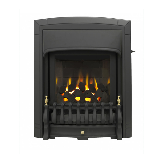
Model 961
Inset live fuel effect gas fire
Incorporating the Valor Fires
Control.
Fitted with one of the following fascia
Homeflame Dream
Homeflame Masquerade
Homeflame Excelsior
Homeflame Harmony
Homeflame Petrus
Homeflame Classica
(G.C. Number 32-032-88)
We trust that this guide gives sufficient details to
enable this appliance to be installed and maintained
satisfactorily.
However, if further information is required, our Valor
Fires Technical Helpline will be pleased to help.
In the United Kingdom
Telephone 0844 879 35 88
(National call rates apply in the United Kingdom).
In the Republic of Ireland
Telephone 01 842 8222
INSTALLER: Please leave this guide with the owner
© GDC Group Ltd. 2012

Advertisement

Table of Contents
loading
Need help?

Need help?

Do you have a question about the Homeflame Dream and is the answer not in the manual?

Questions and answers

Summary of Contents for Valor Homeflame Dream

  • Page 1 We trust that this guide gives sufficient details to enable this appliance to be installed and maintained satisfactorily. However, if further information is required, our Valor Fires Technical Helpline will be pleased to help. In the United Kingdom Telephone 0844 879 35 88 (National call rates apply in the United Kingdom).
  • Page 2 Grange Drive, Hedge End, Southampton, SO30 2DF. Warning: Any person who does any unauthorised act in relation to a copyright work may be liable to criminal prosecution and civil claims for damages. Valor, GDC Group Ltd., Millbrook House, Grange Drive, Hedge End, Southampton, SO30 2DF. www.valor.co.uk...
  • Page 3 BS EN ISO 9001 quality system accepted by the British Standards Institute. The Highest Standards Valor Fires is a member of SBGI and HHIC (Heating and Hot water Industry Council) that work to ensure high standards of safety, quality and performance. Careful Installation...
  • Page 4: Installer Guide

    INSTALLER GUIDE INSTALLER GUIDE FOR OWNER GUIDE SEE PAGES 47 TO 63 © GDC Group Ltd. 2012 Page 4...
  • Page 5: Table Of Contents

    INSTALLER GUIDE CONTENTS Section Heading Page INSTALLER GUIDE 4 - 46 OWNER GUIDE 47 - 63 1. SAFETY AND UNPACKING 2. APPLIANCE DATA, EFFICIENCY AND NOx 2.1 General information. 2.2 Efficiency. 2.3 NOx 3. GENERAL INSTALLATION REQUIREMENTS 3.1 Regulations, Standards and Law. 3.2 Ventilation requirements.
  • Page 6: Installer Guide

    13. OPERATING AND SPILLAGE CHECKS 13.1 Checking the control settings. 13.2 Check for spillage. 13.3 Flame supervision and spillage monitoring system. 14. FASCIA FITTING 14.1 Homeflame Dream/Masquerade/Excelsior/Classica models. 14.2 Homeflame Harmony model. 14.3 Homeflame Petrus model. 15. FINAL REVIEW 16. SERVICING & PARTS REPLACEMENT 16.1 Checking the aeration setting of the burner.
  • Page 7: Safety And Unpacking

    INSTALLER GUIDE 1. SAFETY AND UNPACKING Installer Before continuing any further with the installation of this appliance please read the following guide to manual handling. The lifting weight (kg) of this appliance is as below: Model Heat Engine Firefront Combined Weight Dream/Masquerade/Excelsior 8.64 13.35 21.99...
  • Page 8: Appliance Data, Efficiency And Nox

    INSTALLER GUIDE 2. APPLIANCE DATA, EFFICIENCY AND NO x 2.1 General information. Natural (G20) Inlet Pressure 20mbar Input - Max. (Gross) 5.00kW (17,060 Btu/h) Input - Min. (Gross) 2.5kW (8,530 Btu/h) Inlet Test Pressure (Cold) 20.0 ± 1.0mbar (8.0 ± 0.4in w.g.) Gas Connection 8mm pipe Burner Injector...
  • Page 9: General Installation Requirements

    INSTALLER GUIDE Conversion factor from net to gross efficiency Natural Gas 0.901 2.3 NO x The 'Weighted' result for this appliance equates to NO x Class 2. 3. GENERAL INSTALLATION REQUIREMENTS 3.1 Regulations, Standards and Law. The installation must be in accordance with these instructions. For the user’s protection, in the United Kingdom it is the law that all gas appliances are installed by competent persons in accordance with the current edition of the Gas Safety (Installation and Use) Regulations.
  • Page 10: Ventilation Requirements

    INSTALLER GUIDE In the republic of Ireland the installation must be carried out by a competent person and also conform to the relevant parts of: a) The current edition of IS 813 “Domestic Gas Installations” b) All relevant national and local rules in force. Where no specific instructions are given, reference should be made to the relevant British Standard Code of Practice.
  • Page 11: The Hearth

    INSTALLER GUIDE 3.6.2 Any chimney damper or restrictor should be removed. If removal is not possible, they must be secured in the open position. 3.7 Fireplace preparation. 3.7.1 If the fireplace opening is an underfloor draught type, it must be sealed to stop any draughts.
  • Page 12: Fireplace Clearances

    INSTALLER GUIDE 3.9 Fireplace clearances. 3.9.1 The minimum height from the base of the fireplace opening to the underside of any shelf made from wood or other combustible materials is detailed below. For Dream, Masquerade, Excelsior, Classica and Homeflame Harmony models - •...
  • Page 13 INSTALLER GUIDE 3.9.2 The minimum allowable distance from the outside of the appliance fascia to a corner wall having combustible material or any other combustible surface which projects beyond the front of the appliance is shown in figure 4. A 10mm access clearance from a non-combustible surface is necessary at the left side.
  • Page 14: Installation Options

    INSTALLER GUIDE 3.10 Installation options. In the United Kingdom, as supplied, the appliance can be installed in the following situations: - 3.10.1 Conventional fireplace and hearth. To a fireplace complete with surround and hearth as shown in figure 5 and complying with BS1251 after removal of the fireback and sufficient material behind the fireback for a debris catchment space.
  • Page 15: Hole-In-The-Wall' Installations

    3.10.1.1 ‘Hole-in-the-wall’ Installations. It is recommended that a hearth should be installed as in section 3.8. Homeflame Dream/Masquerade/Excelsior/Classica firefront If a reduced depth hearth is fitted, the fire must be installed so that the distance from the base of the fireplace opening in the wall to the finished floor level is at least 100mm.
  • Page 16: Precast Concrete Or Clay Flue Block System And Hearth

    INSTALLER GUIDE 3.10.3 Precast concrete or clay flue block system and hearth. The appliance can be installed to a precast concrete or clay flue block system conforming to BS EN 1858 with dimensions as in figure 8. BS 1289 part 1 recommends there should be an air space or insulation between the flue blocks and the plaster because heat transfer may...
  • Page 17: Pack Contents

    Section 1 - Fire unit contains: Burner and convection box unit. Burner tray trim (Homeflame Dream and Homeflame Petrus only). Outlet baffle for the convected air outlet (Homeflame Dream only). Tapping Screws for outlet baffle (Homeflame Dream only). Nut and olive for 8mm inlet pipe.
  • Page 18 INSTALLER GUIDE Tapping screws for fascia hood (Dream, Masquerade, Excelsior only). Firefront casting baffle (Dream, Masquerade, Excelsior only). Slider control position label. Upper louvre assembly (Homeflame Petrus only). Hood Dream only). Figure 9. Pack contents (Items are not to scale) ©...
  • Page 19 INSTALLER GUIDE Section 2 - “Homeflame Dream, Masquerade, Excelsior, Classica” fascia pack contains: Fascia and firefront casting. Section 2 - “Homeflame Harmony” fascia pack contains: Fascia. Section 2 - “Homeflame Petrus” fascia pack contains: Fascia and firefront casting. Carefully remove all the contents. Take special care in handling the ceramic pieces.
  • Page 20: Fireplace Check

    INSTALLER GUIDE 5. FIREPLACE CHECK 5.1 Soundness for appliance attachment. Two primary methods of retaining the appliance are provided: - By fixing to the fireplace front surround. Using concealed tension cables fixed to the rear of the fireplace opening together with secondary fixing to the fireplace floor.
  • Page 21: Ignition Check

    INSTALLER GUIDE 6. IGNITION CHECK Before attempting to install, it is worth checking that the electronic ignition system performs satisfactorily. Fit the battery to the ignition block located below the burner tray at the left side (See figure 10). The positive terminal (+) is to the bottom as you insert.
  • Page 22: Preparing Appliance For Installation

    INSTALLER GUIDE 8. PREPARING APPLIANCE FOR INSTALLATION IMPORTANT Before continuing with the installation of this gas fire the aeration setting on the burner must be checked. The aeration is factory set and should not require adjustment. See section 16.1 (Servicing and parts replacement). 1.
  • Page 23 INSTALLER GUIDE 4. Fit the two “U” section seals to the bottom edges of the convection box side flanges (See figure 14). 5. It is important that the grommet supplied in the loose parts pack is fitted to the hole in the rear of the convection box.
  • Page 24: Convection Box Installation

    INSTALLER GUIDE 9. There is a length of self adhesive foam seal supplied with the fire. This will need to be fitted to the outer rear edges of the side and top flanges of the convector box. Cut a 485mm length of foam seal.
  • Page 25: Method 2 - Cable Retention And Floor Fixing

    INSTALLER GUIDE 4. Remove the convection box. Drill four holes in the fireplace front surround at the marked positions using a suitably sized masonry drill for the fibre / wooden plugs supplied. 5. Insert a fibre / wooden plug into each hole. 6.
  • Page 26 INSTALLER GUIDE 6. Thread the cables through the eyebolts. Return the cables through the holes near the bottom of the convection box back panel (See figure 21). 7. Place the convection box fully back into the fireplace opening so that it is sealed against the fireplace front surround.
  • Page 27: Sealing Floor Front - All Installations

    INSTALLER GUIDE 11. Pull each cable taut. Push the cable retainers hard up against the back panel. The end of the cable adjuster will pass into the hole. Tighten the screws in the retainers so that they clamp the cables in position. Apply tension to the cables by turning the hexagonal adjusters by hand (See figure 23).
  • Page 28: Burner And Supply Pipe Installation

    INSTALLER GUIDE 10. BURNER AND SUPPLY PIPE INSTALLATION 10.1 Burner and supply pipe installation. 1. Remove the ‘Aeration checking’ reminder label from the top of the burner. 2. Refit the burner unit to the convection box with the two screws removed previously. 3.
  • Page 29: Inlet Pressure Check

    4. Test around the sealing screw for gas soundness with a suitable leak detection fluid. 5. Homeflame Dream and Homeflame Petrus Figure 26. Pressure test point only - Fit the burner baffle to the front flanges of the burner. To do this, locate the tags on the baffle over the front flanges of the burner and lower into position (See figure 27).
  • Page 30: Fitting The Window Frame Assembly

    INSTALLER GUIDE 12. FITTING THE WINDOW FRAME ASSEMBLY 1. Locate the window mounting frame and window assembly in place. 2. Secure in place using the six screws removed previously. Figure 28. Window mounting frame and window assembly removal 13. OPERATING AND SPILLAGE CHECKS 13.1 Checking the control settings.
  • Page 31: Check For Spillage

    INSTALLER GUIDE 4. Release the button. The button should automatically spring up to the low heat position. If for any reason the slider control does not spring up, raise the slider to the topmost (Off) position and investigate why the slider is not operating correctly. If the flames go out at this stage or when checking the rest of the setting positions, try the full lighting sequence again.
  • Page 32: Flame Supervision And Spillage Monitoring System

    INSTALLER GUIDE 5. If the above test is satisfactory open all internal connecting doors, hatches, etc. in the room. Keep all doors and windows that open to the outside of the building closed. Recheck for spillage as above. If an extractor fan is installed in the same room as the appliance or a connecting room, check that spillage does not occur with the fan operating and all doors and other openings between the fan and the appliance open.
  • Page 33: Fascia Fitting

    Before fitting the fascia ensure that the information on the back pages of the owner guide have been completed. 14.1 Homeflame Dream/Masquerade/Excelsior/Classica models. 14.1.1 Fitting the outlet baffle. Locate the outlet baffle and secure in place using two tapping screws supplied (See fig. 30) Figure 30.
  • Page 34 INSTALLER GUIDE 14.1.3 Fitting the slider knob (Classica only). 1. Supplied loose with the fire is a slider knob. 2. This needs to be screw fixed into the threaded slider metal shaft. (See Figure 32 for the components required). 3. Using the two screws supplied secure the knob in place.
  • Page 35: Homeflame Harmony Model

    INSTALLER GUIDE 14.2 Homeflame Harmony model. 14.2.1 Fitting the fascia. 1. Place the top of the fascia against the fireplace front surface so that the two retaining plates at the back of the fascia are directly above the two retaining brackets on the convector box.
  • Page 36 INSTALLER GUIDE 14.3.2 Fitting the firefront casting and ash pan. 1. Place the firefront firefront casting and ash pan in place. 14.3.2 Fitting the louvre assembly. Please take care when attaching or removing the louvre assembly to avoid marking the fascia surface. 1.
  • Page 37: Final Review

    INSTALLER GUIDE 15. FINAL REVIEW 1. COMPLETE THE INFORMATION IN THE WARRANTY AND SERVICE SECTION OF THE OWNER GUIDE (See last pages of the OWNER guide). 2. Visually inspect the appliance. Clean off any marks incurred during installation. 3. Advise the customer how to operate the appliance. Point out that lighting instruction details are on the metal plate attached at the bottom of the appliance.
  • Page 38: Servicing & Parts Replacement

    INSTALLER GUIDE 16. SERVICING & PARTS REPLACEMENT Always turn off the gas supply before commencing any servicing and allow to cool completely. (The appliance inlet ‘T’ connector incorporates an isolating valve). It is recommended that, at least once a year, the appliance is disconnected and the fireplace opening checked and cleared of any debris.
  • Page 39: To Remove The Ignition Microswitch

    INSTALLER GUIDE 16.2 To remove the ignition microswitch. See figure 38. 1. Remove the bottom front cover and the fire front casting. 2. Disconnect the leads from the ignition microswitch (The lower of the two microswitches - See figure 38). 3.
  • Page 40: To Replace The Control Slide Unit

    INSTALLER GUIDE 16.4.2 Homeflame Harmony model. 1. Carefully lift the fascia upward and forward. 2. Place the fascia in a safe place away from the gas fire. 3. To fit the fascia, place the top of the fascia against the fireplace front surface so that the two retaining plates at the back of the fascia are directly above the two retaining brackets on the convector box.
  • Page 41: To Remove And Fit The Window Mounting Frame And Window Assembly

    INSTALLER GUIDE 16.7 To remove and fit the window mounting frame and window assembly. When servicing the appliance it will be necessary to remove all of the window mounting frame and the window assembly to enable the front coal, ceramic walls and burner to be removed.
  • Page 42: To Remove The Fuel Effect

    INSTALLER GUIDE To fit. 1. Locate the bottom corners of the window assembly. 2. Gently push the window assembly into place and secure with the window clamping brackets. The window clamping brackets have a raised ‘stop’ that will prevent them being rotated too far. Figure 45.
  • Page 43: To Remove The Complete Burner Unit

    INSTALLER GUIDE 6. Remove the two fixing screws that attach the generator unit to the support bracket. The igniter generator can now be removed (See figure 46) 7. Remove the two leads to the switch and remove the spark lead. If necessary, mark them to ensure that they are replaced on to the correct terminals.
  • Page 44: To Remove The Pilot Unit

    INSTALLER GUIDE 16.14 To remove the pilot unit. 1. Remove the burner unit (See section 16.12). 2. Detach the pilot pipe from the pilot unit. 3. Detach the thermocouple from the interrupter block by unscrewing the thermocouple nut. 4. Detach the electrode lead from the underside of the electrode tab.
  • Page 45: To Remove The Gas Flow Rate Controller

    INSTALLER GUIDE When refitting the thermocouple and interrupter block, make sure that the microswitch wires are properly secured to give a good electrical contact. 16.16 To remove the gas flow rate controller. (See figure 50). 1. Remove the burner unit (See section 16.12).
  • Page 46: To Remove The Main Burner Injector

    INSTALLER GUIDE 16.18 To remove the main burner injector. (See figure 52). 1. Remove the burner (See section 16.17). 2. Remove the burner clamping screw (See figure 52). 3. Unscrew the injector from the burner. 4. Refit in the reverse order. Figure 52.
  • Page 47: Owner Guide

    OWNER GUIDE OWNER GUIDE FOR WARRANTY AND SERVICE INFORMATION SEE PAGES 60 TO 63 © GDC Group Ltd. 2012 Page 47...
  • Page 48 The Oxysafe flame sensing and flue blockage safety system. To light the fire. To turn the fire off. Lighting with a taper - Homeflame Dream and Petrus models. Lighting with a taper - Homeflame Harmony model. CLEANING YOUR FIRE Glass and Metal parts.
  • Page 49: Safety

    OWNER GUIDE SAFETY IF YOU SMELL GAS DON’T SMOKE. EXTINGUISH ALL NAKED FLAMES. DON’T TURN ELECTRICAL SWITCHES ON OR OFF. TURN OFF THE GAS SUPPLY AT THE METER. OPEN DOORS AND WINDOWS TO GET RID OF THE GAS. IMMEDIATELY CALL THE GAS EMERGENCY SERVICE FROM A NEIGHBOURS PHONE - SEE YOUR LOCAL TELEPHONE DIRECTORY.
  • Page 50 OWNER GUIDE For Dream, Maquerade, Excelsior, Classica and Harmony models - • For a shelf up to 150mm deep: Minimum height = 700mm. • For a shelf deeper than 150mm: 700mm + 12.5mm for every 25mm depth over 150mm (See Figure 1). Figure 1.
  • Page 51: Gas Consumption

    OWNER GUIDE Don’t hang clothing, towels or any other fabrics over the fire. Don’t add any extra fuel effect pieces above the number stated in the ceramic fuel effect guide. This could cause a safety hazard. The ceramic fuel effect guide should have been attached to, or placed inside this guide by the installer.
  • Page 52: Appliance Dimensions

    APPLIANCE DIMENSIONS OWNER GUIDE Model Dream, Description Masquerade, Harmony Petrus Classica Excelsior Height (mm) Width (mm) Depth into room (mm) Minimum mandatory clearance to combustible surfaces projecting beyond the front of appliance (mm) Recommended clearance to non combustible surfaces for access purposes (mm) Figure 3.
  • Page 53: Operating Your Fire

    OWNER GUIDE OPERATING YOUR FIRE PLEASE NOTE When operating your fire for the first time, some vapours may be given off which may cause a slight odour and could possibly set off any smoke alarms in the immediate vicinity. These vapours are quite normal with new appliances. They are totally harmless and will disappear after a few hours use.
  • Page 54: To Turn The Fire Off

    OWNER GUIDE 3. If low heat is required, release the button. The button will automatically spring up to the low heat position shown in figure 4 (See note i below). If for any reason the slider control does not spring up, raise the slider to the off (O) position (Topmost position) and contact your installer.
  • Page 55: Lighting With A Taper - Homeflame Harmony Model

    OWNER GUIDE Lighting with a taper - Homeflame Harmony model. Important: When lighting with a match or taper be very careful not to place naked flames by the plastic / rubber coated leads. 1. In the unlikely event of failure of the ignition spark, the pilot can be lit by a taper or long spill.
  • Page 56: Cleaning Your Fire

    OWNER GUIDE CLEANING YOUR FIRE To maintain the high performance and quality finish of your fire please follow these guidelines: Before attempting to clean the fire, please remember to turn off the fire and wait for the appliance to cool. The fire will retain heat for some time before cleaning can begin. If any pieces of debris are found in the firebox, have the chimney inspected before further use.
  • Page 57: Ceramic Fuel Effect Pieces And Burner Compartment Walls

    OWNER GUIDE 2. Replace in the reverse order. Figure 8. Window removal Ceramic fuel effect pieces and burner compartment walls. To gain access to the ceramic components the window assembly must be removed as in the previous section. It will not be possible to remove the ceramic compartment walls or ceramic front coal for cleaning.
  • Page 58: Burner

    OWNER GUIDE Burner. To gain access to the burner the window assembly and ceramic components must be removed as in the previous sections. Be careful not to damage the front coal as this will be in situ. Remove any deposits of soot or other foreign matter from the surface of the burner with a dry soft brush.
  • Page 59: Battery Replacement

    OWNER GUIDE MAINTENANCE Battery replacement. Homeflame Dream and Homeflame Petrus models. To replace the battery remove the bottom front cover casting. Fit the new battery firmly to the connections on the ignition block (See figure 9). Homeflame Harmony model. To replace the battery lift the fascia upward and forward.
  • Page 60: Warranty And Service

    OWNER GUIDE WARRANTY AND SERVICE Standard Warranty Terms & Conditions The warranty is for 12 months subject to contract. In the United Kingdom servicing can be carried out either by a GDC approved service engineer or a GAS SAFE REGISTER engineer. Outside of the United Kingdom servicing can be carried out either by a CORGI or GAS SAFE REGISTER engineer.
  • Page 61 OWNER GUIDE When calling the customer helpline, it would be helpful if you could have the following information to hand:- Fire serial number and fascia code (Located on the information label - See figure 10 on page 63)*. Date of installation*. Your installer name and address details*.
  • Page 62 OWNER GUIDE Installer Details (Block Capitals) Installer Name Gas Safe Register or Corgi Registration Number. Company Name. Company Address Company Telephone number Company Fax number © GDC Group Ltd. 2012 Page 62...
  • Page 63 Fascia code - Can be found close to the information label (Block Capitals) A LABEL CONTAINING THE FASCIA CODE MAY HAVE BEEN PLACED INSIDE THIS BOX. Brand (Please tick) Valor Wonderfire Other......Date of Installation Figure 10. Information label location. © GDC Group Ltd. 2012...
  • Page 64 © GDC Group Ltd. 2012...
  • Page 65 © GDC Group Ltd. 2012 Page 65...
  • Page 66 © GDC Group Ltd. 2012 Page 66...

Table of Contents

Save PDF