Valor H4 Series Installation & Owner's Manual
Direct vent natural/propane gas
Hide thumbs
Also See for H4 Series:
- Installation instructions manual (6 pages) ,
- Installation instructions manual (6 pages)
Table of Contents
Advertisement
Quick Links
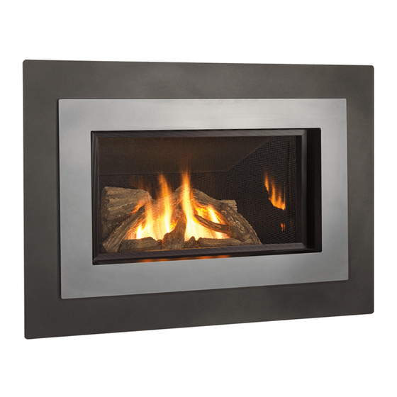
INSTALLATION & OWNER'S MANUAL
Direct Vent Gas Fireplace
650JN (natural gas) & 650JP (propane gas)
DANGER
!
A barrier designed to reduce the risk of burns from the hot
viewing glass is provided with this appliance and must be
installed for the protection of children and other at-risk
individuals.
!
WARNING
FIRE OR EXPLOSION HAZARD
Failure to follow safety warnings exactly
could result in serious injury, death, or
property damage.
— Do not store or use gasoline or other
fl ammable vapors and liquids in the
vicinity of this or any other appliance.
— WHAT TO DO IF YOU SMELL GAS
▪ Do not try to light any appliance.
▪ Do not touch any electrical switch; do
not use any phone in your building.
▪ Leave the building immediately.
▪ Immediately call your gas supplier from
a neighbor's phone. Follow the gas
supplier's instructions.
▪ If you cannot reach your gas supplier,
call the fi re department.
— Installation and service must be
performed by a qualifi ed installer,
service agency or the gas supplier.
4005130-14
© 2020, Miles Industries Ltd. All rights reserved.
H4 Series
HOT GLASS WILL
CAUSE BURNS.
DO NOT TOUCH GLASS
UNTIL COOLED.
NEVER ALLOW CHILDREN
TO TOUCH GLASS.
Please read this manual
BEFORE
operating this appliance.
INSTALLER
Leave this manual
with the appliance.
CONSUMER
Retain this manual
for future reference.
This manual contains instructions to install the EN-
GINE ONLY. A front trim kit is REQUIRED to install
the engine as it aff ects the framing cavity and posi-
tion of the engine. A barrier screen is provided with
the front or trim kit. Refer to the manual supplied
with the front for framing and fi nishing.
This appliance may be installed in an after-
market permanently located, manufactured
(mobile) home where not prohibited by local
codes.
This appliance is only for use with the type
of gas indicated on the rating plate. This
appliance is not convertible for use with
other gases, unless a certifi ed kit is used.
This appliance is a domestic room-heating
appliance. It must not be used for any other
purposes such as drying clothes, etc.
This appliance is suitable for installation in
a bedroom or bed sitting room.
Ce guide est disponible en français sur demande.
installing and
Advertisement
Table of Contents

Related Manuals for Valor H4 Series


Summary of Contents for Valor H4 Series
- Page 1 INSTALLATION & OWNER’S MANUAL H4 Series Direct Vent Gas Fireplace 650JN (natural gas) & 650JP (propane gas) DANGER Please read this manual BEFORE installing and operating this appliance. HOT GLASS WILL CAUSE BURNS. INSTALLER DO NOT TOUCH GLASS Leave this manual UNTIL COOLED.
-
Page 2: Table Of Contents
Also, see Carbon Monoxide Detector requirements on page 50. Designed and Manufactured by / for Miles Industries Ltd. 190–2255 Dollarton Highway, North Vancouver, BC, CANADA V7H 3B1 Tel. 604-984-3496 Fax 604-984-0246 www.valorfi replaces.com © Copyright Miles Industries Ltd., 2020... -
Page 3: Safety And Your Fireplace
Safety and Your Fireplace SAFETY AND YOUR FIREPLACE Read and understand all instructions carefully before Do not use this heater as a temporary source of starting the installation. Failure to follow these instal- heat during construction. lation instructions may result in possible fi re hazard and Due to the high temperature, the appliance should be will void the warranty. - Page 4 Safety and Your Fireplace Read and carefully follow all safety warnings and operating instructions contained in your owner’s manual Replacement manuals are available by contacting the Valor Service Department at 1-800-468-2567 or visit www.valorfi replaces.com. FOLLOW THESE IMPORTANT CHILD SAFETY...
- Page 5 SAFETY AND YOUR FIREPLACE This manual and particularly the preceeding and following pages contain very important information regarding before operating your the safe operation of your fi replace as well as maintenance instructions. Read carefully fi replace and pay special attention to the safety warnings. A heating gas appliance does require safe handling.
-
Page 6: Introduction
Each Valor fi replace curing compounds used in the manufacture of the is fully tested during the production process for your appliance. -
Page 7: Operating Your Fireplace
OWNER’S Operating Your Fireplace INFORMATION Fireplace Control Devices Alternately, turn off gas supply. In all cases, call your dealer for service assistance. There are two ways to control your fi replace. 1. Thermostatic Remote Control; 2. Wall Switch. ON: parallel to pipe OFF: perpendicular to pipe... -
Page 8: Using The Remote Control
OWNER’S Using the Remote Control INFORMATION Radio Frequency Turn Fireplace ON 315 MHz for USA and Canada. Press buttons until you hear a short beep; release buttons. This device complies with Part 15 of the FCC Rules and with Industry Canada license-exempt RSS standard(s). Beeping continues until pilot is lit. - Page 9 OWNER’S Using the Remote Control INFORMATION Setting ºC/24-hr or ºF/12-hr clock Manual Mode M A N In MAN mode, press and hold Manual ame height adjustment. buttons until temperature / clock display changes from Daytime Temperature Mode TEMP When pilot is lit, room temperature °F / 12-hour °C / 24-hour is measured and compared to set...
- Page 10 OWNER’S Using the Remote Control INFORMATION Setting high / low Temperatures Setting Program Timers Setting “DAYTIME” high temperature. You can program two periods of time between 12 am and 11:50 pm in each 24-hour cycle. Default Settings: 23 °C/74 °F TEMP Programs P1 and P2 must be set in the following order Press SET to scroll to...
- Page 11 OWNER’S Using the Remote Control INFORMATION Setting P2 high and low temperature times. Repeat same steps as Setting P1. When all settings are complete, press to save them. Timer Programming Example (default temperatures shown) 6:00 am 8:00 am 4:00 pm 10:00 pm 6:00 am high temp...
-
Page 12: Using The Wall Switch
Remote Battery & Wall Switch Kit 620FBL Fluted Black Liners 755CFK Circulating Fan Kit Hearth 621VRL Valor Red Brick Liners Hearth gates such as Cardinal’s VersaGates are available at retail stores Gate 622LSL Ledgestone Liners carrying safety products for children. -
Page 13: Lighting Instructions
OWNER’S Lighting Instructions INFORMATION... -
Page 14: Servicing & Maintenance
OWNER’S Servicing & Maintenance INFORMATION Servicing Your Fireplace We recommend having your fi replace serviced every year. Contact your supplier quoting the model number. It will be helpful if the appliance’s serial number can also be quoted. These numbers are on the information card. -
Page 15: Cleaning Your Fireplace
OWNER’S Servicing & Maintenance INFORMATION Cleaning Your Fireplace Clean the window panes following the guidelines in this section. WARNING Clean the steel trim with mild soap and warm water. DO NOT TOUCH THE GLASS WHILE IT IS HOT! Any alcohol/solvent base cleaner will weaken the coat- Let the fi... - Page 16 Damage caused by incorrect window installa- fi rebox. tion is not covered by the Valor warranty. 7. If the Hot Glass Warning plate has been removed from the front lower corner of the window, 1.
-
Page 17: Checking Pilot And Burner Flames
OWNER’S Servicing & Maintenance INFORMATION Checking Pilot and Burner Flames The appliance area must always be kept clear and free from combustible materials, gasoline and other A periodic check of the pilot and burner fl ames should fl ammable vapors and liquids. Inspect the vent terminal be made. -
Page 18: Replacing Batteries
OWNER’S Servicing & Maintenance INFORMATION Replacing Batteries 2. Disconnect the battery holder from the cable. WARNING DO NOT ATTEMPT TO CHANGE THE BATTER- IES WHILE THE FIREPLACE IS STILL HOT! Let the fi replace cool fi rst before touching it. CAUTION DO NOT USE a screwdriver or other metallic object to remove the batteries from the battery holder or... -
Page 19: Specifi Cations
QUALIFIED Specifi cations INSTALLER Approvals & codes Supply Gas These appliances are certifi ed by ANSI Z21.88 / Heater engine units 650JN are used with natural gas CSA 2.33 American National Standard / CSA Standard installations. for Vented Gas Fireplace Heaters for use in Canada Heater engine units 650JP are used with propane gas and USA. -
Page 20: Overview
QUALIFIED Overview INSTALLER Note: This appliance may be installed in outdoor, weather protected environments as defi ned in the GV60CKO Outdoor Conversion Kit instruction manual. Framing—See Framing section Remote Handset Wall Holder Field convertible Min. from top to rear 3/4” outlet (19 mm) Fire On/Off... -
Page 21: Dimensions
QUALIFIED Dimensions INSTALLER MINIMUM 3/4” (19 mm) 8-1/4” (210 mm) clearance to combustible From finished at rear wall surface to top vent MINIMUM 3/4” (19 mm) from finished Stand-off wall surface to front of 3” (76 mm) min. appliance To side wall from inner frame in front of the appliance... -
Page 22: Framing
QUALIFIED Framing INSTALLER • A non-combustible hearth is not necessary in front of this appliance. • Note that the unit is installed at the framing stage and fi xed to framing using support angles. See page 32. The wall fi nish is then installed over the support angles up to the front frame on the unit, on the sides and up to the stand-off... -
Page 23: Location
QUALIFIED Location INSTALLER Venting Vent Material Vent Penetration through Walls & Ceilings This unit is approved for installation using 4 x 6-5/8 Combustible: When penetrating through combustible inches approved co-axial direct vent pipes and acces- walls and ceilings, frame a minimum of 10 inch x 10 sories listed on pages 48–49 of this guide. -
Page 24: Co-Axial Venting
QUALIFIED Co-Axial Venting INSTALLER Typical Co-Axial Venting Components VERTICAL TERMINATION STORM COLLAR FLASHING ATTIC INSULATION SHIELD ATTIC FIRESTOP CEILING FIRESTOP HORIZONTAL 2-PIECE TERMINATION 90˚ ELBOW PIPE WALL PIPE LENGTH THIMBLE LENGTH PIPE LENGTH PIPE LENGTH 817VAK 817VAK... - Page 25 QUALIFIED Co-Axial Venting INSTALLER Co-Axial Venting Rear Vent with No Vertical Rise The horizontal vent run cannot be extended by the use of any vent accessory pipes. Vent pipe max. 26” (660 mm) max. 15” (381 mm) vent length after 45° elbow (14”...
- Page 26 QUALIFIED Co-Axial Venting INSTALLER Horizontal Vent Termination Location air ow or a safety hazard. Local codes or regulations may require greater clearances. • The vent terminal must be located on an outside wall or through the roof. • The vent terminal must not be recessed into a wall or siding.
- Page 27 QUALIFIED Co-Axial Venting INSTALLER Co-Axial Venting Confi gurations with Vertical Rise 4 x 90º ELBOWS MAXIMUM (or equivalent) 3” min. above top of horizontal pipe 1” min. all around vertical pipe 1” min. around bottom & sides of horizontal pipe Min.
- Page 28 QUALIFIED Co-Axial Venting INSTALLER How to Read the Venting Chart 5. Each 90 degrees elbow installed on the horizontal plane is equivalent to a 3 feet horizontal pipe; The chart below applies to co-axial roof or wall therefore, 3 feet must be subtracted from allowable termination in installations with vertical rise.
- Page 29 QUALIFIED Co-Axial Venting INSTALLER Co-Axial Vertical Installations Overhang should • Check the roof pitch to determine which roof not extend beyond vent if within 48” of fl ashing will be needed. See venting accessories list Horizontal termination cap starting on page 48 for allowable components. overhang •...
-
Page 30: Co-Linear Venting
Secure the appliance to the fl oor or wall if necessary. 2 x 3” Rear or Top Outlet Conversion to Co-Linear liners engine Liners using Valor 556CLA Co-Linear Adapter. NOTE: Min. 1/2” Co-linear Co-linea adapter adapter gap required... -
Page 31: Installation
QUALIFIED Installation INSTALLER Remove Window 1. Turn the top two spring-loaded window bolts through 90 degrees to release the window from the fi rebox. 2. Remove the bottom two spring-loaded window bolts. 3. Carefully lift the window away. Keep the window and bolts in a safe place. Convert to Rear Vent Outlet (if required) If installing with top vent outlet, ignore this stage. -
Page 32: Install Top Stand-Off And Support Angles
QUALIFIED Installation INSTALLER Install Top Stand-off and Support Angles Thickness of wall finish + extra 3/4” (19 mm) The distance from the support angles to the front face (Appliance MUST project 3/4” (19 mm) in front of the wall finish surface) of the heater case is adjustable to allow for a range of Fix to appliance wall fi... -
Page 33: Install Air Restrictors
QUALIFIED Installation INSTALLER Install Air Restrictors No restrictors are required for appliances which only have a horizontal vent run. If installing an appliance which has a rear vent outlet connection and no vertical vent pipe rise, ignore this stage. Two restrictor sets, like the one shown at right, are supplied with each 650 engine unit. Adjustable piece The restrictors cover part of the inlet air openings in the fi... -
Page 34: Connect Gas Supply
QUALIFIED Installation INSTALLER Connect Gas Supply • Failure to either disconnect or isolate the appliance during pressure testing may result in regulator or The gas supply pipe valve damage. Consult your dealer in this case. should enter the appliance The minimum supply pressure is given in the case through the opening Specifi... -
Page 35: Install Liner Panels
QUALIFIED Installation INSTALLER Install Liner Panels 4. Insert the top panel over the left side panel while holding the top panel forward up the slope. Rotate All liner panels can be installed as indicated below the right side of the top panel upwards and place it except the 618RGL—Refl... -
Page 36: Install 534Lsk Traditional Logs
QUALIFIED Installation INSTALLER Install 534LSK Traditional Logs Unpack the ceramic logs very carefully to avoid damaging their fragile material. Install the logs as shown below. Please note that the position of the logs is critical to insure the good performance of the appliance. 1. - Page 37 QUALIFIED Installation INSTALLER 6. Place the lower end of the center right log onto the pin on the front right log. Rest the narrow end in the notch into the rear log. Notch in rear log Pin in front right log 7.
-
Page 38: Install 534Rsk Ceramic Rocks
QUALIFIED Installation INSTALLER Install 534RSK Ceramic Rocks Unpack the ceramic rocks kit very carefully to avoid damaging the fragile material. Install the components as shown below. Please note that the position of the rocks and twigs (if used) is critical to ensure proper performance of the appliance. - Page 39 QUALIFIED Installation INSTALLER 4. The underside of each ceramic rock is identi- fi ed by a number and a specifi c protruding positioning triangle. Rock identifi - cation Install the six rocks from left to right starting with rock no. 1. Triangular hole in ce- ramic base...
-
Page 40: Install 534Dwk Driftwood Kit
QUALIFIED Installation INSTALLER Install 534DWK Driftwood Kit 2. Identify the rear log and place it on top of the base log locating it into the notches on top of the log. Pull Unpack the driftwood kit very carefully to avoid the log forward so it is locked in position. - Page 41 QUALIFIED Installation INSTALLER Pebbles 4. Identify the right side cross log, the longest, and place it across the rear log. The narrow end of the Six pebbles are supplied as decorative elements. log rests in a notch of the rear log. The wide end of If used, they should be placed on the platform only.
-
Page 42: Refi T And Check Window, Install Window Baffl E
fi replace, damage components, cause overheating resulting in dangerous conditions. Window Baffl e Damage caused by incorrect window installa- tion is not covered by the Valor warranty. window frame Rear view detail—window assembly with window baffl e hooked on frame window baffl... - Page 43 QUALIFIED Installation INSTALLER 7. If the Hot Glass Warning plate has been removed from the front lower corner of the window, reinstall it by sliding it between the glass and the frame as indicated below. Safety warning plate...
-
Page 44: Install Wall Switch Kit (Required)
QUALIFIED Installation INSTALLER 7. Insert 4 AA alkaline batteries in the battery holder. Install Wall Switch Kit (required) 8. Connect the battery holder wire to the receiver. The wall switch kit is provided with this appliance. It is connected to the receiver in the fi replace. The receiver 9. -
Page 45: Synchronize Remote Control
QUALIFIED Installation INSTALLER Synchronize Remote Control The receiver and the handset of the remote control sys- tem must be initially synchronized before fi rst use. 1. Insert one 9 V alkaline battery in the handset. 2. Locate the Reset button on the top side of the re- ceiver. -
Page 46: Install Front, Trim And Barrier Screen
QUALIFIED Installation INSTALLER Install Front, Trim and Barrier Screen Install the front or trim chosen by the customer for their fi replace. Install as well the barrier screen which is provided with the front or trim. Show the customer how to access the controls when the front or trim are installed and how to remove them. -
Page 47: Wiring Diagram
QUALIFIED Wiring Diagram INSTALLER Wall Switch Kit Connector GV60 Wiring Diagram Battery Holder 4 AA Batteries... -
Page 48: Approved Venting Components
QUALIFIED Approved Venting Components INSTALLER... - Page 49 QUALIFIED Approved Venting Components INSTALLER...
-
Page 50: Commonwealth Of Massachusetts
QUALIFIED Commonwealth of Massachusetts INSTALLER State of Massachusetts Carbon Monoxide 3. SIGNAGE. A metal or plastic identifi cation plate shall be permanently mounted to the exterior of the Detector/Vent Terminal Signage building at a minimum height of eight (8) feet above Requirements grade directly in line with the exhaust vent terminal for For all side wall horizontally vented gas fueled... - Page 51 QUALIFIED Commonwealth of Massachusetts INSTALLER (d) MANUFACTURER REQUIREMENTS - GAS EQUIPMENT VENTING SYSTEM NOT PROVIDED. When the manufacturer of a Product Approved side wall horizontally vented gas fueled equipment does not provide the parts for venting the fl ue gases, but identifi...
-
Page 52: Warranty
Installation and maintenance must be performed by 5. No Other Warranty an authorized and trained dealer in accordance with All obligations to repair this unit are de ned in this warranty. -
Page 53: Replacement Parts
Refl ective glass 618RGL 11a Flashback shield (propane gas) 3000371 Ceramic fl uted black 620FBL 11b Air shutter cover (natural gas) 4002346 Valor red brick 621VRL 12a Air shutter slider (propane gas) 320B293 Ledgestone 622LSL 12b Air shutter slider (natural gas) 4002345... - Page 54 OWNER’S Replacement Parts INFORMATION Description Part no. 12-inch Top stand-off 4002121 Rock Set Complete 534RSK Rock No. 1 4001821 Rock No. 2 4001822 Rock No. 3 4001823 Rock No. 4 4001824 Rock No. 5 4001825 Rock No. 6 4001826 Rock Base 4001792 LH Twig 4001827...
- Page 55 OWNER’S Replacement Parts INFORMATION Natural gas Propane gas 40a, 40b...
- Page 57 Thank You ... For purchasing a Valor by Miles Industries. Your new radiant gas heater is a technical appliance that must be installed by a qualifi ed installer. Please fi ll in the information below. The information provided will be used for customer records only.
- Page 58 Tape Shut Fold here Postage needed Valor Fireplaces 190 - 2255 Dollarton Highway North Vancouver, BC V7H 3B1 Canada Online Warranty registration at www.valorfi replaces.com Thank you for choosing a Valor Product...
Need help?
Do you have a question about the H4 Series and is the answer not in the manual?
Questions and answers
Valor H4-650J Gas Fireplace. When trying to ignite pilot light by simultaneously pressing the red off button and the flame button. It tries to start but doesn’t. It is issuing 4 repetitive beets. I’ve changed the battery. How do I fix this?
If your Valor H4-650J Gas Fireplace is beeping four times and the pilot light is not igniting, the likely issue is low batteries. Follow these steps to fix it:
1. Turn off the fireplace completely, including the pilot.
2. Let the fireplace cool before touching it.
3. Unhook the inner front with the barrier screen.
4. Locate the battery holder near the receiver at the bottom of the fireplace behind the surround trim.
5. Pull out the battery holder carefully and disconnect it (do not pull on the wire).
6. Remove the old batteries and replace them with 4 new AA 1.5V alkaline batteries. Do not mix old and new batteries.
7. Reconnect the battery holder and reassemble the fireplace.
Do not use metal tools to remove batteries, as this could cause a short circuit.
This answer is automatically generated