
Subscribe to Our Youtube Channel
Related Manuals for Fujitsu Siemens Computers D1260


Summary of Contents for Fujitsu Siemens Computers D1260
- Page 1 S Y S T E M B O A R D D 1 2 6 0 S Y S T E M B O A R D D 1 2 6 0 S Y S T E M B O A R D D 1 2 6 0 S Y S T E M B O A R D D 1 2 6 0 USER'S MANUAL USER'S MANUAL...
- Page 2 Are there ..any technical problems or other questions you would like to be clarified? Please contact: • your sales partner • your sales outlet You will find further information in the manual "Safety, Guarantee and Ergonomics". The latest information on our products, tips, updates, etc., can be found on the Internet under: http://www.fujitsu-siemens.com...
- Page 4 Este manual ha sido impreso sobre papel reciclado. Questo manuale è stato stampato su carta da riciclaggio. Denna handbok är tryckt på recyclingpapper. Dit handboek werd op recycling-papier gedrukt. Herausgegeben von/Published by Fujitsu Siemens Computers GmbH A26361-D1260-Z120-1-7619 A26361-D1260-Z120-1-7619 A26361-D1260-Z120-1-7619 A26361-D1260-Z120-1-7619 Bestell-Nr./Order No.:...
- Page 5 Introduction Features SYSTEM BOARD D1260 Hardware Setup BIOS Setup User's Manual November 2000 edition...
- Page 6 Copyright ã Fujitsu Siemens Computers GmbH 2000 Intel, Pentium and Celeron are registered trademarks and MMX and OverDrive are trademarks of Intel Corporation, USA. Microsoft, MS, MS-DOS and Windows are registered trademarks of Microsoft Corporation. PS/2 and OS/2 Warp are registered trademarks of International Business Machines, Inc.
-
Page 7: Table Of Contents
4.1 Managing and Updating Your BIOS ......... 37 4.1.1 Upon First Use of the Computer System ....... 37 4.1.2 Updating BIOS Procedures ........... 38 4.2 BIOS Setup Program ..............40 4.2.1 BIOS Menu Bar ............. 41 4.2.2 Legend Bar ..............41 D1260 CUR-DLSR User’s Manual... - Page 8 4.4.3 PCI Configuration ............52 4.4.4 Shadow Configuration ............. 54 4.5 Power Menu ................55 4.5.1 Power Up Control ............57 4.5.2 Hardware Monitor ............59 4.6 Boot Menu ................60 4.7 Exit Menu ................. 62 D1260 CUR-DLSR User’s Manual...
-
Page 9: Federal Communications Commission Statement
Radio Interference Regulations of the Canadian Department of Communications. This Class B digital apparatus complies with Canadian ICES-003. Cet appareil numérique de la classe B est conforme à la norme NMB-003 du Canada. D1260 CUR-DLSR User’s Manual... -
Page 11: Introduction
Instructions on setting up the BIOS 5. SOFTWARE SETUP Instructions on setting up the included software 6. SOFTWARE REFERENCE Reference material for the bundled software 7. APPENDIX Optional items and general reference CUR-DLSR means Coppermine RCC Dual LAN SCSI Rack. D1260 CUR-DLSR User’s Manual... -
Page 12: Features
2. FEATURES 2.1 D1260 CUR-DLSR Motherboard The D1260 CUR-DLSR motherboard is designed primarily for multi-server environments to optimize available space without sacrificing performance. Powered ® ® by dual Intel Pentium III processors, the CUR-DLSR efficiently complies with today’s demand for a high-integration server. - Page 13 CPU and systerm voltages, temperatures, and fan status through the onboard hardware ASIC. • Enhanced ACPI: Programmable BIOS (Flash EEPROM), offering enhanced ACPI for Windows NT and Windows 2000 compatibility, and autodetection of most devices for virtually automatic setup. D1260 CUR-DLSR User’s Manual...
-
Page 14: Performance
Plug and Play compatibility and power management for configuring and managing all system components, and 32-bit device drivers and installation procedures for Windows NT/2000. Color-coded connectors and descriptive icons make identification easy as required by PC 99. D1260 CUR-DLSR User’s Manual... -
Page 15: Intelligence
Remote management response via remote diagnostics and troubleshooting work even when the operating system has frozen. Remote power down for power management. Asset tracking and monitoring through features like presence ping and logoff notification. D1260 CUR-DLSR User’s Manual... - Page 16 Power ATX Power Supply Connector ..........4 CMOS Battery Lithium CR2032 3V .............. 19 Special Feature LSI 64-bit (66/33MHz) Ultra160 / Ultra3 dual channel SCSI controller ............... 12 Onboard SCSI Connectors ........... 8, 9 Form Factor Full-size AT D1260 CUR-DLSR User’s Manual...
-
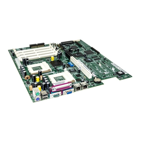
Page 17: Component Locations
2. FEATURES 2.2.1 Component Locations 15 14 13 D1260 CUR-DLSR User’s Manual... -
Page 18: Hardware Setup
P C I_ EX TPW R PANEL2 CR2032 3V Lithium Cell CMOS Power SCSI-A IDE2 68-Pin Ultra 160/Ultra3-Wide SCSI Connector ServerWorks RCC-IB6566 South Bridge RAGE XL LSI SCSI Controller Controller 53C1010-33 SCSI-B Super ASMCSA 4Mbit WOL_CON Flash BIOS ASMCSB D1260 CUR-DLSR User’s Manual... -
Page 19: Layout Contents
22) SPEAKER (PANEL) p.29 System Warning Speaker Connector (4 pins) 23) IDELED (PANEL) p.29 IDE/SCSI Activity LED (2 pins) 24) ATXPWR p.30 ATX Power Connector (20 pins) 25) SCSI-A/SCSI-B p.31 68-pin Ultra160/Ultra3 SCSI Connectors (two 68 pins) D1260 CUR-DLSR User’s Manual... -
Page 20: Hardware Setup Procedure
4. Place components on a grounded antistatic pad or on the bag that came with the component whenever the components are separated from the system. 5. Ensure that the ATX power supply is switched off before you plug in or remove the ATX power connector on the motherboard. D1260 CUR-DLSR User’s Manual... -
Page 21: System Memory
16M x 4 Double-Sided Double-Sided & Stacked 128Mbit 32M x 4 Double-Sided Double-Sided & Stacked 128Mbit 16M x 8 Single-Sided Double-Sided 256Mbit 32M x 8 Single-Sided Double-Sided 256Mbit 64M x 4 Single-Sided Double-Sided & Stacked 1024 D1260 CUR-DLSR User’s Manual... -
Page 22: Dimm Installation
The notches on the DIMM shift between left, center, or right to identify the type and also to prevent the wrong type from being inserted into the DIMM slot on the motherboard. Ask your retailer the correct DIMM type before purchasing. D1260 CUR-DLSR User’s Manual... -
Page 23: Central Processing Unit (Cpu)
Gold Arrow Socket 370 Pentium III Silver Arrow Socket 370 Terminator (Use when only one CPU is installed) CUR-DLSR CUR-DLSR Socket 370 IMPORTANT: An optional CPU terminator is required when installing only one CPU. D1260 CUR-DLSR User’s Manual... -
Page 24: Expansion Cards
9. If you installed a long expansion card, pull down the metal card guide and fit it to the other end of the card to hold the card in place. 10. Install the necessary software drivers for your expansion card. Expansion Card Locking Tab Riser Card PCI Slot D1260 CUR-DLSR User’s Manual... -
Page 25: Isa Interrupt (Irq) Assignments
ISA 15* Secondary IDE Channel *These IRQs are usually available for PCI devices. PCI Interrupt (IRQ) Assignments PCI Slot PCI INTA PCI INTB PCI INTC PCI INTD 64-bit PCI 0 PCI 3 PCI 4 PCI 5 D1260 CUR-DLSR User’s Manual... -
Page 26: Ports And Connectors
This connection is for a standard keyboard using an PS/2 plug (mini DIN). This connector does not allow standard AT size (large DIN) keyboard plugs. You may use a DIN to mini DIN adapter on standard AT keyboards. PS/2 Keyboard (6-pin Female) D1260 CUR-DLSR User’s Manual... - Page 27 Local Area Network (LAN) through a network hub. RJ45 RJ45 5) Parallel Port (Burgundy 25-pin PRINTER) You can enable the parallel port and choose the IRQ through Onboard Parallel Port (see 4.4.2 I/O Device Configuration). Parallel Port (25-pin Female) D1260 CUR-DLSR User’s Manual...
- Page 28 (Pin 5 is removed to prevent inserting in the wrong orientation when using ribbon cables with pin 5 plugged). PIN 1 CUR-DLSR NOTE: Orient the red markings on the floppy ribbon cable to PIN 1. CUR-DLSR Floppy Disk Drive Connector D1260 CUR-DLSR User’s Manual...
- Page 29 SCSI drive and select the boot disk through Boot Sequence in 4.6 Boot Menu. PIN 1 IDE2 PIN 1 CUR-DLSR NOTE: Orient the red markings CUR-DLSR IDE Connectors (usually zigzag) on the IDE ribbon cable to PIN 1. D1260 CUR-DLSR User’s Manual...
- Page 30 IMPORTANT: This feature requires that PCI Modem card is enabled (see 4.5.1 Power Up Control) and that your system has an ATX power supply with at least 720mA +5V standby power. Ground Ring# CUR-DLSR CUR-DLSR Wake-On-Ring Connector D1260 CUR-DLSR User’s Manual...
- Page 31 CPU fan if these pins are incorrectly used. These are not jumpers, do not place jumper caps over these pins. CPU_FAN1 / CPU_FAN2 Rotation +12V CHA_FAN1 / CHA_FAN2 CUR-DLSR CUR-DLSR 12-Volt Cooling Fan Power D1260 CUR-DLSR User’s Manual...
- Page 32 This 2-pin connector (see the preceding figure) connects to the case-mounted suspend switch. D1260 CUR-DLSR User’s Manual...
- Page 33 This 4-pin connector connects to the case-mounted speaker. 23) IDE Activity LED (2-pin) This connector supplies power to the IDE activity LED. Read and write activity by devices connected to the Primary or Secondary IDE connectors will cause the LED to light up. D1260 CUR-DLSR User’s Manual...
- Page 34 25) Serial Port 2 Connector This motherboard has a second serial port connector to accommodate additional serial peripherals. See the BIOS section 4.4.2 I/O Device Configuration to configure Serial Port 2 settings. PIN 1 CUR-DLSR CUR-DLSR Serial COM2 Connector D1260 CUR-DLSR User’s Manual...
- Page 35 CUR-DLSR Panel 2 Connector 27) Power Button Connector This connector allows you to turn the system ON or OFF. The power LED lights up when the system is turned ON. PWRBTN CUR-DLSR CUR-DLSR Power Button Connector D1260 CUR-DLSR User’s Manual...
- Page 36 Make sure that your ATX power supply can supply at least 720mA on the +5-volt standby lead (+5VSB). You may experience difficulty in turning ON your system if your power supply cannot support the load. CUR-DLSR CUR-DLSR ATX Power Connector D1260 CUR-DLSR User’s Manual...
- Page 37 Each channel can support a maximum of 15 devices as specified by Ultra160/Ultra3 standards. SCSI-A (Internal) 68-Pin Ultra160/Ultra2-Wide SCSI Connector SCSI-B (External) 68-Pin Ultra160/ Ultra2-Wide SCSI Connector CUR-DLSR CUR-DLSR Onboard SCSI Connectors D1260 CUR-DLSR User’s Manual...
-
Page 38: Scsi Connection Notes
Terminator CUR-DLSR Internal SCSI Devices (up to 15 devices) CUR-DLSR SCSI Connection Example NOTE: Ultra160/Ultra3 SCSI devices do not have termination jumpers and must use a separate terminator on the last connector (internal) or device (external). D1260 CUR-DLSR User’s Manual... -
Page 39: Switches
To erase the RTC RAM: (1) Unplug your computer, (2) Short the solder points, (3) Turn ON your computer, (4) Hold down the <Del> key during bootup and enter BIOS setup to re-enter user preferences. R266 CLRTC Short solder points CUR-DLSR to Clear CMOS CUR-DLSR Clear RTC RAM D1260 CUR-DLSR User’s Manual... -
Page 40: Starting Up The First Time
No DRAM installed or detected One long beep followed by Video card not found or video card three short beeps memory bad High frequency beeps when CPU overheated system is working System running at a lower frequency D1260 CUR-DLSR User’s Manual... - Page 41 If you use Windows 9X, click the Start button, click Shut Down, and then click Shut down the computer? The power supply should turn off after Windows shuts down. NOTE: The message “You can now safely turn off your computer” does not appear when shutting down with ATX power supplies. D1260 CUR-DLSR User’s Manual...
-
Page 42: Bios Setup
Press ESC To Exit IMPORTANT! If “unknown” is displayed after Flash Memory:, the memory chip is either not programmable or is not supported by the ACPI BIOS and therefore, cannot be programmed by the Flash Memory Writer utility. D1260 CUR-DLSR User's Manual... -
Page 43: Updating Bios Procedures
Flash Memory: Winbond W29C020 or SST 29EE020 or Intel 82802AB Current BIOS Version: ASUS XXX-XX ACPI BIOS Revision 100X BIOS Model : XXX-XX BIOS Built Date : 09/25/99 Please Enter File Name for NEW BIOS: A:\XXX-XX.XXX D1260 CUR-DLSR User's Manual... - Page 44 BIOS file you saved to disk above. If the Flash Memory Writer utility was not able to successfully update a complete BIOS file, your system may not be able to boot up. If this happens, your system will need servicing. D1260 CUR-DLSR User's Manual...
-
Page 45: Bios Setup Program
To access the BIOS Setup program, press the <Delete> key after the computer has run through its POST. NOTE: Because the BIOS software is constantly being updated, the following BIOS screens and descriptions are for reference purposes only and may not reflect your BIOS screens exactly. D1260 CUR-DLSR User's Manual... -
Page 46: Bios Menu Bar
Brings up a selection menu for the highlighted field <Home> or <PgUp> Moves the cursor to the first field <End> or <PgDn> Moves the cursor to the last field <F5> Resets the current screen to its Setup Defaults <F10> Saves changes and exits Setup D1260 CUR-DLSR User's Manual... -
Page 47: D1260 Cur-Dlsr User's Manual
Setup program, note that explanations appear in the Item Specific Help window located to the right of each menu. This window displays the help text for the currently highlighted field. NOTE: The item heading in square brackets represents the default setting for that field. D1260 CUR-DLSR User's Manual... -
Page 48: Main Menu
Legacy Diskette A [1.44M, 3.5 in.], Legacy Diskette B [None] Sets the type of floppy drives installed. Configuration options: [None] [360K, 5.25 in.] [1.2M , 5.25 in.] [720K , 3.5 in.] [1.44M, 3.5 in.] [2.88M, 3.5 in.] D1260 CUR-DLSR User's Manual... -
Page 49: Primary & Secondary Master/Slave
(such as with FDISK) and then formatted before data can be read from and write on. Primary IDE hard disk drives must have its partition set to active (also possible with FDISK). Other options for the Type field are: [None] - to disable IDE devices D1260 CUR-DLSR User's Manual... - Page 50 This field configures the number of cylinders. Refer to your drive documentation to determine the correct value to enter into this field. NOTE: To make changes to this field, the Type field must be set to [User Type HDD] and the Translation Method field must be set to [Manual]. D1260 CUR-DLSR User's Manual...
- Page 51 Ultra DMA capability allows improved transfer speeds and data integrity for compatible IDE devices. Set to [Disabled] to suppress Ultra DMA capability. NOTE: To make changes to this field, the Type field must be set to [User Type HDD]. Configuration options vary according to your device. D1260 CUR-DLSR User's Manual...
-
Page 52: Keyboard Features
30 characters per second. Configuration options: [6/Sec] [8/Sec] [10/Sec] [12/Sec] [15/Sec] [20/Sec] [24/Sec] [30/Sec] Keyboard Auto-Repeat Delay [1/4 Sec] This field sets the time interval for displaying the first and second characters. Configuration options: [1/4 Sec] [1/2 Sec] [3/4 Sec] [1 Sec] D1260 CUR-DLSR User's Manual... - Page 53 Errors] [No Error] [All but Keyboard] [All but Disk] [All but Disk/Keyboard] Installed Memory [XXX MB] This display-only field displays the amount of conventional memory detected by the system during bootup. You do not need to make changes to this field. D1260 CUR-DLSR User's Manual...
-
Page 54: Advanced Menu
This functions as an update loader integrated into the BIOS to supply the processor with the required data. In the default position of [Enabled], the BIOS will load the update on all processors during system bootup. Configuration options: [Disabled] [Enabled] D1260 CUR-DLSR User's Manual... -
Page 55: Chip Configuration
Configuration options: [UC] [USWC] Onboard PCI IDE Enable [Both] You can select to enable the primary IDE channel, both the primary and secondary channels, or disable both channels. Configuration options: [Both] [Primary] [Disabled] D1260 CUR-DLSR User's Manual... -
Page 56: I/O Device Configuration
[EPP] allows bidirectional parallel port operation; [ECP] allows the parallel port to operate in bidirectional DMA mode; [ECP+EPP] allows normal speed operation in a two-way mode. Configuration options: [Normal] [EPP] [ECP] [ECP+EPP] D1260 CUR-DLSR User's Manual... -
Page 57: Pci Configuration
These fields set how IRQ use is determined for each PCI slot. The default setting for each field is [Auto], which utilizes auto-routing to determine IRQ use. Configuration options: [Auto] [NA] [3] [4] [5] [7] [9] [10] [11] [12] [14] [15] PCI Latency Timer [32] Leave on default setting for best performance vs. stability. D1260 CUR-DLSR User's Manual... - Page 58 This field, when set to [Yes], gives priority to the onboard VGA BIOS over other VGA controllers. Configuration options: [No] [Yes] Onboard LAN Boot ROM [Disabled] When set to [Enabled], this field allows your computer to boot from the network using the onboard LAN controller boot ROM. Configuration options: [Disabled] [Enabled] D1260 CUR-DLSR User's Manual...
-
Page 59: Shadow Configuration
ROMs on them, you will need to know which addresses the ROMs use to shadow them specifically. Shadowing a ROM reduces the memory available between 640K and 1024K by the amount used for this purpose. Configuration options: [Disabled] [Enabled] D1260 CUR-DLSR User's Manual... -
Page 60: Power Menu
CONFIG.SYS file. For Windows 3.x and Windows 95, you need to install Windows with the APM feature. For Windows 98 and later, APM is automatically installed. A battery and power cord icon labeled “Power Management” will appear in the “Control Panel.” Choose “Advanced” in the Power Management Properties dialog box. D1260 CUR-DLSR User's Manual... - Page 61 This feature does not affect SCSI hard drives. Configuration options: [Disabled] [1 Min] [2 Min] [3 Min]...[15 Min] Suspend Mode [Disabled] This sets the time period before the system goes into suspend mode. Configuration options: [Disabled] [1~2 Min] [2~3 Min]...[1 Hour] D1260 CUR-DLSR User's Manual...
-
Page 62: Power Up Control
Wake-On-LAN allows your computer to be booted from another computer via a network by sending a wake-up frame or signal. Configuration options: [Disabled] [Enabled] IMPORTANT: This feature requires an optional network interface card with Wake-On-LAN and an ATX power supply with at least 720mA +5V standby power. D1260 CUR-DLSR User's Manual... - Page 63 [Everyday] or at a certain time and day by selecting [By Date]. NOTE: Automatic Power Up will not work if the system is powered down by operating systems, such as Windows 98, which have ACPI support enabled. Configuration options: [Disabled] [Everyday] [By Date] D1260 CUR-DLSR User's Manual...
-
Page 64: Hardware Monitor
Set to [Ignore] only if necessary. NOTE: If any of the monitored items is out of range, an error message will appear: “Hardware Monitor found an error. Enter Power setup menu for details”. You will then be prompted to “Press F1 to continue, DEL to enter SETUP”. D1260 CUR-DLSR User's Manual... -
Page 65: Boot Menu
This field allows you to select which ATAPI CD-ROM drive to use in the boot sequence. Pressing [Enter] will show the product IDs of all your connected ATAPI CD-ROM drives. Other Boot Device Select [INT18 Device (Network)] Configuration options: [Disabled] [SCSI Boot Device] [INT18 Device (Network)] D1260 CUR-DLSR User's Manual... - Page 66 This field speeds up the Power-On-Self Test (POST) routine by skipping retesting a second, third, and fourth time. Configuration options: [Disabled] [Enabled] Boot Up Floppy Seek [Enabled] When enabled, the BIOS seeks the floppy disk drive once during bootup. Configuration options: [Disabled] [Enabled] D1260 CUR-DLSR User's Manual...
-
Page 67: Exit Menu
This option should only be used if you do not want to save the changes you have made to the Setup program. If you have made changes to fields other than system date, system time, and password, the system will ask for confirmation before exiting. D1260 CUR-DLSR User's Manual... - Page 68 This option saves your selections without exiting the Setup program. You can then return to other menus and make changes. After selecting this option, all selections are saved and a confirmation is requested. Select [Yes] to save any changes to the non-volatile RAM. D1260 CUR-DLSR User's Manual...
Need help?
Do you have a question about the D1260 and is the answer not in the manual?
Questions and answers