Table of Contents
Advertisement
Advertisement
Table of Contents

Related Manuals for Fujitsu Siemens Computers D1818


Summary of Contents for Fujitsu Siemens Computers D1818
-
Page 1: Mainboard D1818
Mainboard English Technical Manual Mainboard D1818... - Page 2 • our hotline for customers who have purchased the mainboard as a single delivery unit: +49(0) 180 3777 005 The latest information and updates (e.g. BIOS update) on our mainboards can be found on the Internet under: http://www.fujitsu-siemens.com/mainboards...
- Page 4 Questo manuale è stato stampato su carta da riciclaggio. Denna handbok är tryckt på recyclingpapper. Dit handboek werd op recycling-papier gedrukt. Herausgegeben von/Published by Fujitsu Siemens Computers GmbH Printed in the Federal Republic of Germany AG 0905 09/05 Ausgabe/Edition 1...
- Page 5 English Mainboard D1818 Technical Manual September 2005 edition...
- Page 6 Alle weiteren genannten Warenzeichen sind Warenzeichen oder eingetragene Warenzeichen der jeweiligen Inhaber und werden als geschützt anerkannt. Copyright Fujitsu Siemens Computers GmbH 2005 Alle Rechte vorbehalten, insbesondere (auch auszugsweise) die der Übersetzung, des Nachdrucks, der Wiedergabe durch Kopieren oder ähnliche Verfahren.
-
Page 7: Table Of Contents
Information about boards ......................2 List of features ............................3 Board Installation ..........................5 Board Image ............................5 D1818 Block Diagram........................... 6 Board Parts, Jumpers and Connectors .................... 7 Front Panel Audio Header (W) ..................... 9 USB (Front Panel Header) (N) ..................... 9 Front Panel Header (S) ...................... -
Page 9: Mainboard D1818
This symbol indicates that you must press the Enter key. Text in this typeface indicates screen outputs. Text in this bold typeface indicates the entries you make via the keyboard. Text in italics indicates commands or menu items. "Quotation marks" indicate names of chapters or terms. A26361-D1818-Z120-1-7619, edition 1... -
Page 10: Important Notes
The equipment and tools you use must be free of static charges. • Remove the power plug from the mains supply before inserting or removing boards containing ESDs. • Always hold boards with ESDs by their edges. • Never touch pins or conductors on boards fitted with ESDs. A26361-D1818-Z120-1-7619, edition 1... -
Page 11: List Of Features
Four 4-pin fan headers with tachometer monitoring and speed control • One PC2004 PSU Fan header with tachometer monitoring • 3-pin Chassis Intrusion header Integrated Enhanced IDE Controller • Two ports for up to four EIDE devices • Supports up to ATA-133 A26361-D1818-Z120-1-7619, edition 1... - Page 12 Phoenix TrustedCore on 8Mbit LPC Flash ROM • ACPI - 2.0 • PXE via Ethernet • USB device boot Form Factor • SSI EEB v3.0 footprint (13 x12” 330.2x304.8 mm) • EPS12V SSI Workstation Spec 2.0 (24pin + 8pin) power connector A26361-D1818-Z120-1-7619, edition 1...
-
Page 13: Board Installation
Board Installation Board Installation The mainboard D1818 supports EPS12V/SSI type power supplies (24pin + 8pin) and will not operate with any other types. For proper power supply installation procedures see "Installing the power supply” section DO NOT USE ATX 2.x, ATX12V or ATXGES power supplies as they will damage the board and void your warranty. -
Page 14: D1818 Block Diagram
Board Installation D1818 Block Diagram This diagram is representative of the latest board revision available at the time of publishing. The board you receive may not look exactly like the above diagram. A26361-D1818-Z120-1-7619, edition 1... -
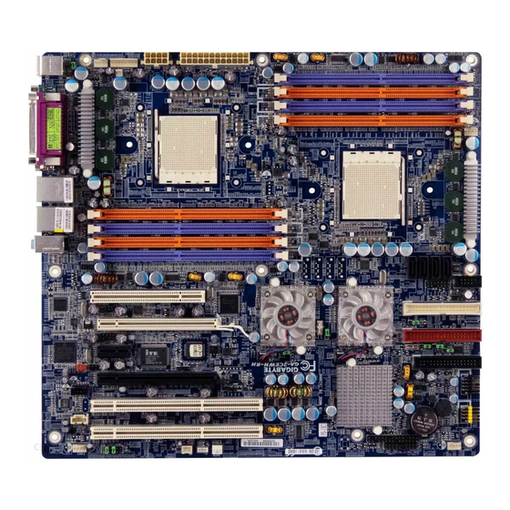
Page 15: Board Parts, Jumpers And Connectors
Board Parts, Jumpers and Connectors Board Parts, Jumpers and Connectors A26361-D1818-Z120-1-7619, edition 1... - Page 16 AUDIO SATA1 USB_LAN2 SATA2 USB_LAN1 SATA3 REAR_1394 F_Panel_FS SPDIF_OUT (not supported) Battery WOL (Wake On LAN) KB_MS (Keyboard/Mouse) F_AUDIO ATX1 (SSI power connector) WOR (Wake On Ring) ATX2 (SSI power connector) AUX_IN PC 2004 (power connector) CD_IN1 A26361-D1818-Z120-1-7619, edition 1...
-
Page 17: Front Panel Audio Header (W)
WARNING: Do not place jumpers on this header in any other configuration. Doing so could result in damage to the motherboard! USB (Front Panel Header) (N) F_USB1 USB E/F (Front Panel Header) Signal Signal Data - Data - Data + Data + A26361-D1818-Z120-1-7619, edition 1... -
Page 18: Front Panel Header (S)
+ 3.3.V SCSI_LED_Input HD_LED_C n.c. Coded PWR_Button_L SLP_Button_L Reset_L USB (with Chipcardreader support) (M) F_USB2 USB D (with Chipcardreader support) Signal Signal CCR on n.c. n. c. Data + n. c. Data - n. c. n. c. A26361-D1818-Z120-1-7619, edition 1... -
Page 19: Lcd Header (26)
LCD header Signal Signal Clock Data LAN Action LAN Link Alert Message Sleep Power INTR – Chassis Intrusion Header (U) INTR – Chassis Intrusion Header Active Low Pin 1 Presence Detect Pin 2 Case Open Pin 3 A26361-D1818-Z120-1-7619, edition 1... -
Page 20: Chassis Fan Connectors
IO4 and CK8-04 Fan Specifications ( 5 / 6 ) These Fans headers use the same pinout, listed on the left CK8-04 FAN: Cooling of NVidia nForce Pro 2200 IO4 FAN: Cooling of NVidia nForce Pro 2050 A26361-D1818-Z120-1-7619, edition 1... -
Page 21: Jumper
Board Parts, Jumpers and Connectors 3. Jumper 2) PWR_JP 3) CLR_CMOS1 4) BIOS_RE 5) BIOS_WP Jumper Legend OPEN - Jumper OFF without jumper cover CLOSED - Jumper ON with jumper cover Key Pin Missing pin to indicate proper orientation A26361-D1818-Z120-1-7619, edition 1... -
Page 22: Clear Cmos Jumper (3)
Closed – Pin1 and Pin2Top Block Protect Closed – Pin 3 and Pin4 Block 2-8 Protect PS/2 Wake Up Power Source Jumper (2) PWR_JP 2-3 close: Disable this function 1-2 close: support PS/2 wake up from S3 (Default) A26361-D1818-Z120-1-7619, edition 1... -
Page 23: Add-On Modules / Upgrading
CPU0 memory banks are addressable. There must be used identical processors for CPU0 and CPU1. Fujitsu Siemens Computers is not liable for damage as a result of operating an unsupported configuration. The diagram is provided as a visual guide to help you install socket processors and may not be an exact representation of the processors you have. -
Page 24: Installing The Memory
The following diagram shows common types of DDR SDRAM modules: Here are a few key points to note before installing memory into your mainboard D1818. • Always install memory beginning with DIMM3 and DIMMM2. -
Page 25: Attaching Drive Cables
Attaching the IDE drive cable is simple. These cables are “keyed” to only allow them to be connected in the correct manner. The mainboard D1818 has two on-board IDE channels, each supporting two drives. The black connector designates the Primary channel, while the white connector designates the Secondary channel. -
Page 26: Connecting Aux/Cd Sound Cables & Speakers
The maximum supported length of an IDE cable is 18”. • There are no Master/Slave jumpers on SATA drives. The mainboard D1818 is also equipped with four Serial ATA (SATA) channels. The following pictures illustrate how to connect an SATA drive. SATA drive cable connection... -
Page 27: Installing Add-In Cards
Connecting external devices to the motherboard is an easy task. The standard devices you should expect to plug into the motherboard are keyboards, mice, and printer cables. The following diagram will detail the ATX port stack for the mainboard D1818: 1 PS/2 Keyboard and PS/2 Mouse Connector To install a PS/2 port keyboard and mouse, plug the mouse to the upper port (green) and the keyboard to the lower port (purple). - Page 28 Speed Yellow BLINK Port identification with 1 Gbps connection Green 100 Mbps connection Green BLINK Port identification with 10 or 100 Mbps connection 10 Mbps connection 8 Audio Connectors Analog Connectors Line in Line out Microphone In A26361-D1818-Z120-1-7619, edition 1...
-
Page 29: Installing The Power Supply
Installing the Power Supply There are three power connectors on your mainboard D1818. The mainboard D1818 requires an EPS12V (24-pin + 8-pin) power supply to boot. Please be aware that ATX 2.x and ATXGES power supplies are not compatible with the board and can damage the motherboard and/or CPU(s). -
Page 30: Replacing Lithium Battery
Press the locking lug in the direction of the arrow; the battery jumps somewhat out of the Ê holder (1). Remove the battery (2). Ê Insert a new lithium battery of the same type into the socket (3). Ê A26361-D1818-Z120-1-7619, edition 1... -
Page 31: Bios Update
Add-on modules / Upgrading BIOS update When should a BIOS update be carried out? Fujitsu Siemens Computers makes new BIOS versions available to ensure compatibility to new operating systems, new software or new hardware. In addition, new BIOS functions can also be integrated. -
Page 32: Glossary
Graphics and Memory Controller Video Graphic Adapter Graphics Performance Wake On LAN Accelerator Inter Integrated Circuit Wake on Ring IAPC Instantly Available Power Managed Desktop PC Design I/O Controller Hub Intelligent Drive Electronics IPSEC Internet Protocol Security A26361-D1818-Z120-1-7619, edition 1...
Need help?
Do you have a question about the D1818 and is the answer not in the manual?
Questions and answers