Table of Contents
Advertisement
Quick Links
TECHNISCHES HANDBUCH
TECHNISCHES HANDBUCH
TECHNISCHES HANDBUCH
TECHNISCHES HANDBUCH
TECHNICAL MANUAL
TECHNICAL MANUAL
TECHNICAL MANUAL
TECHNICAL MANUAL
S Y S T E M B A U G R U P P E D 1 1 3 2
S Y S T E M B A U G R U P P E D 1 1 3 2
S Y S T E M B A U G R U P P E D 1 1 3 2
S Y S T E M B A U G R U P P E D 1 1 3 2
S Y S T E M B O A R D D 1 1 3 2
S Y S T E M B O A R D D 1 1 3 2
S Y S T E M B O A R D D 1 1 3 2
S Y S T E M B O A R D D 1 1 3 2
Advertisement
Table of Contents

Related Manuals for Fujitsu Siemens Computers D1132


Summary of Contents for Fujitsu Siemens Computers D1132
- Page 1 S Y S T E M B A U G R U P P E D 1 1 3 2 S Y S T E M B A U G R U P P E D 1 1 3 2 S Y S T E M B A U G R U P P E D 1 1 3 2 S Y S T E M B A U G R U P P E D 1 1 3 2 S Y S T E M B O A R D D 1 1 3 2...
- Page 2 Sie haben ..technische Fragen oder Probleme? Wenden Sie sich bitte an: • einen unserer Servicepartner • Ihren zuständigen Vertriebspartner • Ihre Verkaufsstelle Aktuelle Informationen zu unseren Produkten, Tipps, Updates usw. finden Sie im Internet: http://www.fujitsu-siemens.com Is there ..
- Page 3 Is there ..any technical problem or other question you need clarified? Please contact: • Our Hotline: Mo-Fr: 8 a.m. - 6 p.m. Sat: 9 a.m. - 2 p.m. Tel.: ++49 (0) 180 3777 005 • your sales outlet The latest information on our products, tips, updates, etc., can be found on the Internet under: http://www.fujitsu-siemens.com.
- Page 4 Este manual ha sido impreso sobre papel reciclado. Questo manuale è stato stampato su carta da riciclaggio. Denna handbok är tryckt på recyclingpapper. Dit handboek werd op recycling-papier gedrukt. Herausgegeben von/Published by Fujitsu Siemens Computers GmbH A26361-D1132-Z120-1-7419 A26361-D1132-Z120-1-7419 A26361-D1132-Z120-1-7419 A26361-D1132-Z120-1-7419 Bestell-Nr./Order No.:...
- Page 5 Deutsch li h English Systembaugruppe D1132 System Board D1132 Technisches Handbuch Technical Manual Ausgabe Januar 2000 January 2000 edition...
- Page 6 Copyright ã Fujitsu Siemens Computers GmbH 2000 Intel, Pentium und Celeron sind eingetragene Warenzeichen und MMX und OverDrive sind Warenzeichen der Intel Corporation, USA. Microsoft, MS, MS-DOS und Windows sind eingetragene Warenzeichen der Microsoft Corporation. PS/2 und OS/2 Warp sind eingetragene Warenzeichen von International Business Machines, Inc.
-
Page 7: Table Of Contents
..................10 Write protection for floppy disks - switch 3 ................10 Add-on modules ..........................11 Installing / removing processor ....................12 Upgrading main memory......................13 Installing network board with WOL................... 14 Replacing the lithium battery....................14 Glossary ............................15 A26361-D1132-Z120-3-7419... -
Page 9: Introduction
Please note the information provided in the chapter "Safety" in the Operating Manual of the device. Incorrect replacement of the lithium battery may lead to a risk of explosion. It is therefore essential to observe the instructions in the chapter "Add-on modules“ - "Replacing the lithium battery“. English - 1 A26361-D1132-Z120-3-7419... -
Page 10: Information On Boards
The equipment and tools you use must be free of static charges. • Pull out the power plug before inserting or pulling out boards containing ESDs. • Always hold boards with ESDs by their edges. • Never touch pins or conductors on boards fitted with ESDs. 2 - English A26361-D1132-Z120-3-7419... -
Page 11: Features
(16C550 compatible with FIFO). This port does not support the ring indicator signal. • 1 internal WOL interface • 2 external PS/2 interfaces for keyboard and mouse • 2 external USB ports (USB = Universal Serial Bus) • Real-time clock/calendar with integrated battery backup English - 3 A26361-D1132-Z120-3-7419... -
Page 12: Interfaces And Connectors
2 = PS/2 mouse port 6 = USB port 1 3 = PS/2 keyboard port 7 = LAN port 4 = Parallel port The components and connectors marked do not have to be present on the system board. 4 - English A26361-D1132-Z120-3-7419... - Page 13 5 = IDE drives 3 and 4 (secondary) 13 = Power supply monitoring 6 = Wake On LAN 14 = Cover monitoring 7 = Connector for front panel The components and connectors marked do not have to be present on the system board. English - 5 A26361-D1132-Z120-3-7419...
-
Page 14: Temperature Monitoring / System Monitoring
Unauthorized opening of the cover is detected, even when the system is switched off. However, this will not be indicated until the system is operating again. Voltage monitoring: The voltages 12 V, 5 V and the CMOS battery are monitored. 6 - English A26361-D1132-Z120-3-7419... -
Page 15: Lan Port
The LAN RJ45 connector is equipped with a yellow and a green LED (light emitting diode). 1 = Yellow indicator 2 = Green indicator Green a connection exists (e. g. to a hub). Yellow Link Mode: the LAN connection is active. WOL mode: a Magic Packet is being received. English - 7 A26361-D1132-Z120-3-7419... -
Page 16: Resource Table
The following table shows which PCI bus interrupts on the system board are assigned. PCI bus interrupt Component on system board: PCI bus slot 1 AGP slot PCI bus slot 2 PCI bus slot 3 USB controller LAN controller 8 - English A26361-D1132-Z120-3-7419... -
Page 17: Settings With Switches
Switch 1 = must be set to off Switch 3 = Write protection for floppy Switch 2 = System BIOS recovery (RCV) disks Switch 4 = reserved The clock frequency of the processor is set automatically. It cannot be changed manually. English - 9 A26361-D1132-Z120-3-7419... -
Page 18: Recovering System Bios - Switch 2
BIOS Setup must be disabled (in menu Security, the field Diskette Write must be set to Enabled). The floppy disk drive is write-protected. Read, write and delete floppy disks is possible (default setting). 10 - English A26361-D1132-Z120-3-7419... -
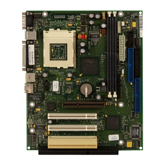
Page 19: Add-On Modules
3 = AGP slot 7 = Location bank 1 for main memory 4 = Voltage indicator LED 8 = Location bank 2 for main memory AGP and PCI slots support 3.3 V main and auxiliary voltages. English - 11 A26361-D1132-Z120-3-7419... -
Page 20: Installing / Removing Processor
The angled corner of the processor may be covered by the heat sink. In this case let yourself be guided by the marking in the rows of pins on the underside of the processor. Ê Push the lever back down so that it snaps into place. 12 - English A26361-D1132-Z120-3-7419... -
Page 21: Upgrading Main Memory
At the same time flip the lateral holders upwards until the memory module snaps in place. Removing a memory module Ê Flip the holders to the right and left of the location outwards. Ê Pull the memory module out of its location. English - 13 A26361-D1132-Z120-3-7419... -
Page 22: Installing Network Board With Wol
Brukte batterier kasseres i henhold til fabrikantens instruksjoner. Ê Lift the contact (1) a few millimeters and remove the battery from its socket (2). Ê Insert a new lithium battery of the same type in the socket (3). 14 - English A26361-D1132-Z120-3-7419... -
Page 23: Glossary
SDRAM ....... Synchronous Dynamic Random Access Memory SGRAM ....... Synchronous Graphic Random Access Memory SMBus......System Management Bus SVGA ......Super Video Graphic Adapter USB......Universal Serial Bus VGA ......Video Graphic Adapter WOL ......Wake On LAN English - 15 A26361-D1132-Z120-3-7419...
Need help?
Do you have a question about the D1132 and is the answer not in the manual?
Questions and answers