Table of Contents
Advertisement
Quick Links
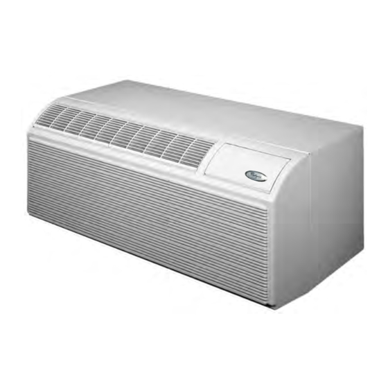
PACKAGED
TERMINAL
AIR
CONDITIONERS
CONSUMER SERVICES TECHNICAL
EDUCATION GROUP PRESENTS
Models: ATE0743SPP, ATE0943SPP, ATE1243SPP, ATE1545SPP,
ATR0743SPP, ATR0943SPP, ATR1243SPP, ATR1545SPP
ATE0953SPP, ATE1253SPP, ATE1555SPP,
ATR0953SPP, ATR1253SPP, ATR1555SPP,
ATE0743RPP, ATE0943RPP, ATE1243RPP, ATE1545RPP,
ATR0743RPP, ATR0943RPP, ATR1243RPP, ATR1545RPP
R-99
JOB AID
Part No. 8178315
Advertisement
Table of Contents
Troubleshooting

Related Manuals for Whirlpool ATE0743SPP


Summary of Contents for Whirlpool ATE0743SPP
- Page 1 CONSUMER SERVICES TECHNICAL R-99 EDUCATION GROUP PRESENTS PACKAGED TERMINAL CONDITIONERS Models: ATE0743SPP, ATE0943SPP, ATE1243SPP, ATE1545SPP, ATR0743SPP, ATR0943SPP, ATR1243SPP, ATR1545SPP ATE0953SPP, ATE1253SPP, ATE1555SPP, ATR0953SPP, ATR1253SPP, ATR1555SPP, ATE0743RPP, ATE0943RPP, ATE1243RPP, ATE1545RPP, ATR0743RPP, ATR0943RPP, ATR1243RPP, ATR1545RPP JOB AID Part No. 8178315...
- Page 2 FORWARD This Whirlpool Job Aid, “Packaged Terminal Air Conditioners” (Part No. 8178315), provides the technician with information on the installation, operation, and service of the Packaged Terminal Air Conditioners . It is to be used as a training Job Aid and Service Manual. For specific information on the model being serviced, refer to the “Use and Care Guide,”...
-
Page 3: Table Of Contents
TABLE OF CONTENTS Page GENERAL ..........................1-1 Whirlpool Model & Serial Number Designations ..............1-1 Model & Serial Number Label & Wiring Diagram Locations ..........1-2 Specifications ........................1-3 Whirlpool Packaged Terminal Air Conditioner (PTAC) And Packaged Terminal Heat Pump (PTHP) Warranty ............1-4 INSTALLATION INFORMATION ................... - Page 4 COMPONENT TESTING ......................5-1 Indoor Thermostat ......................5-1 Mode (System) Switch ....................... 5-2 Heat Anticipator ......................... 5-2 Defrost Thermostat (Emergency Heat Switch) ..............5-3 Hot Start Relay ........................5-4 Hot Start Sensor ........................ 5-4 Capacitor ........................... 5-5 Fan Cycle Switch & Remote Control Unit Fan Switch ............5-5 Heater &...
-
Page 5: General
GENERAL WHIRLPOOL MODEL & SERIAL NUMBER DESIGNATIONS MODEL NUMBER MODEL NUMBER A T R 12 4 3 S P P 0 PRODUCT GROUP A = AIR CONDITIONER PRODUCT IDENTIFICATION T = PTAC, WHIRLPOOL MODEL TYPE R = HEAT PUMP W/AUXILIARY HEAT... -
Page 6: Model & Serial Number Label & Wiring Diagram Locations
MODEL & SERIAL NUMBER LABEL & WIRING DIAGRAM LOCATIONS The Model/Serial Number label and Wiring Diagram locations are shown below. Wiring Diagram Location Model & Serial (Front Cover Removed) Number Location... -
Page 7: Specifications
SPECIFICATIONS ATE-SERIES PTAC W/ELECTRIC HEAT — COOLING PERFORMANCE Heating Dehum- Plug Amps- NEMA Control Cooling BTU Volts Heater Whirlpool Model Pts/Hr Type* Breaker Plug Type 230/208v Electric ATE0743SPP Standard 7500/7000 11600 12.2 6-20 20 Amp ATE0943SPP Standard 9200/9000 11600 11.3... -
Page 8: Packaged Terminal Heat Pump (Pthp) Warranty
2. Damage resulting from accident, alteration, misuse, abuse, fire, floods, acts of God, improper installation not in accordance with local electrical and plumbing codes, or use of products not approved by Whirlpool Corporation, or Whirlpool Canada, Inc. -
Page 9: Installation Information
INSTALLATION INFORMATION ELECTRICAL REQUIREMENTS Electrical Shock Hazard Electrical Shock Hazard Electrically ground PTAC/PTHP. Plug into a grounded 3 prong outlet. Connect ground wire to green pigtail lead. Do not remove ground prong. Use copper wire for supply connection. Do not use an adapter. Correct wire gauge is shown in the chart Do not use an extension cord. -
Page 10: Drain Kit Installation
DRAIN KIT INSTALLATION LOCATION REQUIREMENTS NOTES: Determine whether the drain will be located • Unpack and dispose of packaging materials. on the exterior of the wall, internally in the wall • The drain kit accessory contains 10 com- cavity or internally in the room. plete drain kits. - Page 11 INTERNAL DRAIN INSTALLATION Position the assembly beneath the drilled holes and secure it with #10 - 24 x 1/2″ (Located Inside The Wall Cavity Or machine screws and locknuts (provided). In The Interior Of The Room) Seal the tops of the screws with silicone NOTE: If installing an internal drain, install drain sealant.
- Page 12 EXTERNAL DRAIN INSTALLATION (Located On The Exterior Of The Wall) Peel the backing tape from the gaskets and mount them on the curved side of one cover plate and one mounting plate. Place the drain tube through the gasket and the mounting plate with the flange toward the wall sleeve.
-
Page 13: Chassis Installation
CHASSIS INSTALLATION Remove banding and carton. Remove the 2 chassis shipping brackets from the ends of the shipping pallet. Excessive Weight Hazard Use two or more people to move and install PTAC/PTHP. Failure to do so can result in back or other injury. - Page 14 INSTALL THE CHASSIS Locate the 4 - #10 x 1″ chassis mounting screws (provided). Tighten the screws into the wall sleeve screw clips. Electrical Shock Hazard Disconnect power before servicing. Replace all parts and panels before operating. Failure to do so can result in death or electrical shock.
- Page 15 Cord Connected Models FIELD WIRING CONNECTIONS Disconnect power. Remove the PTAC/PTHP front cover us- ing the thumbscrews. Route the incoming power supply through suitable conduit to the PTAC/PTHP con- trol box. Remove the 4 screws holding the control box. Electrical Shock Hazard Plug into a grounded 3 prong outlet.
- Page 16 Install field-supplied conduit into the same Connect the chassis pigtail wires to the hole as the original bushing for the chassis incoming power supply wires using the UL pigtail wires on the control box. listed wire nuts (provided). Connect the black wire to the incoming L1 (black) wire.
-
Page 17: Remote Wall Thermostat Installation
REMOTE WALL THERMOSTAT INSTALLATION INSTALLATION REQUIREMENTS LOCATION REQUIREMENTS • Unpack and dispose of packaging materials. For best performance, thermostat should be mounted: • This thermostat is a wall mounted, low-volt- age thermostat that maintains room tem- • Approximately 5 ft (152.4 cm) from floor. perature by controlling the operation of the •... - Page 18 Installing The New Thermostat Route the 24 volt thermostat wire along- side the conduit or service cord to the Disconnect power to avoid product dam- location chosen for the thermostat. age during installation of new thermostat. Separate the front housing and back plate Remove the PTAC/PTHP front cover.
- Page 19 13. Reattach the PTAC/PTHP front cover. thermostat. Random Restart Feature After a power outage, the Whirlpool digital ther- mostat will wait between 3 and 5 minutes be- fore allowing the unit to restart. This is to keep multiple units from restarting at the same time when power is restored, thus preventing a cir- cuit overload.
- Page 20 — NOTES — 2-12...
-
Page 21: Product Operation
PRODUCT OPERATION THEORY OF OPERATION Refrigeration Operation The refrigeration system uses the following The refrigerant leaves the compressor through four basic principles in its operation: the discharge line as a hot, high pressure gas. The refrigerant enters the condenser coil where Heat always flows from a warmer body to it gives up some of its heat. - Page 22 The refrigerant leaves the condenser coil as a Since the blower is moving indoor air across warm high pressure liquid. It then passes the finned surface of the evaporator coil, the through the filter/drier (if so equipped). It is the expanding refrigerant absorbs some of the function of the filter/drier to trap any moisture, heat.
-
Page 23: Heat Pump Operation
Heat Pump Operation COOLING All air conditioners are basically heat pumps. allows heat to be transferred from the outdoors They move, or “pump,” heat from inside a room into the room. When the reversing valve is not to the outdoors. A heat pump air conditioner energized, the system operates in the cooling adds a component called a “reversing valve.”... -
Page 24: Reversing Valve Operation
Reversing Valve Operation PILOT VALVE SOLENOID DE-ENERGIZED (COOLING) PILOT VALVE (SOLENOID DE-ENERGIZED) The operation of the reversing valve is gov- erned by the pilot solenoid coil. There are two small lines going to the pilot valve, and two lines going from the pilot valve to the main valve body. -
Page 25: Remote Thermostat Operation
Remote Thermostat Operation ROOM THERMOSTATS HEAT ANTICIPATORS Room thermostats are controlled by the use of Heat anticipators are small resistance heaters a remote thermostat that will cycle the air that are built into most electromechanical ther- conditioner to maintain the desired room tem- mostats (wired in series with the control “W”... - Page 26 CALCULATING THE EXAMPLE: The measured voltage to the unit is 230 volts. The measured current draw of the APPROXIMATE CFM heaters is 11.0 amps. The approximate CFM actually being delivered 230 x 11.0 = 2530 can be calculated by using the following for- 2530 ÷...
-
Page 27: Heat Pump Function
Heat Pump Function THE HOT START SENSOR Emergency Heat Operation Only: In the event of a compressor malfunction in the “heat pump” Under cold room conditions, (50°F, or below), mode, turn the adjustment screw to the ex- the Hot Start Sensor turns on the heater strips treme counterclockwise “emergency heat”... -
Page 28: Operating The Controls
OPERATING THE CONTROLS TEMPERATURE CONTROL TEMPERATURE LIMITING THERMOSTAT The temperature control is a full range thermo- stat that maintains room temperature at the The temperature limiting thermostat allows the desired setting for both heating and cooling. temperature range of the thermostat to be Turn the knob counterclockwise for a warmer varied. - Page 29 FAN CYCLE SWITCH REMOTE THERMOSTAT The fan cycle switch is located behind the Remote thermostat units are controlled with a decorative front cover and below the control remote thermostat that is usually mounted on box. The switch is designed to operate the fan a wall.
- Page 30 — NOTES — 3-10...
-
Page 31: Component Access
COMPONENT ACCESS This section instructs you on how to service each component inside the Packaged Terminal Air Conditioner. The components and their locations are shown below. COMPONENT LOCATIONS Reversing Valve & Solenoid Coil Condenser Fan Motor (Heat Pump Models Only) Compressor &... -
Page 32: Removing The Indoor Thermostat, Mode (System) Switch, And Heat Anticipator
REMOVING THE INDOOR THERMOSTAT, MODE (SYSTEM) SWITCH, AND HEAT ANTICIPATOR Remove the four hex-head screws from the control chassis. Indoor Thermostat Screws Electrical Shock Hazard Disconnect power before servicing. Replace all parts and panels before operating. Failure to do so can result in death or electrical shock. - Page 33 To remove the mode switch: 10. To remove the heat anticipator: a) Raise the locking tab with a screwdriver a) Disconnect the orange wires from the blade, rotate the switch body to the indoor thermostat and mode switch ter- right approximately 1/4-turn, and re- minals.
-
Page 34: Removing The Power Supply Cord
REMOVING THE POWER SUPPLY CORD Ground Screw Electrical Shock Hazard Disconnect power before servicing. Replace all parts and panels before operating. Strain Relief Failure to do so can result in death or Power Cord electrical shock. Leads (L1 & L2) Unplug air conditioner or disconnect power. -
Page 35: Removing The Defrost Thermostat
REMOVING THE DEFROST THERMOSTAT Disconnect the wires from the defrost ther- mostat terminals. Remove the two hex-head screws from the defrost thermostat. Remove the outdoor grille from the rear of the unit. Pull the sensing tube out of the condenser Electrical Shock Hazard and push the tube into the front of the unit Disconnect power before servicing. -
Page 36: Removing The Hot Start Relay And Hot Start Sensor
REMOVING THE HOT START RELAY AND HOT START SENSOR To remove the hot start relay: a) Disconnect the wires from the relay terminals. b) Remove the two hex-head screws from the relay and remove it. Electrical Shock Hazard BR-Defrost Thermostat Disconnect power before servicing. -
Page 37: Removing The Capacitor & Fan Cycle Switch
REMOVING THE CAPACITOR & FAN CYCLE SWITCH (Green Ring) (White Ring) 2 RD & YL (Black Ring) Electrical Shock Hazard Clamp Clamp Screw Disconnect power before servicing. Screw Replace all parts and panels before operating. Failure to do so can result in death or electrical shock. -
Page 38: Removing The Remote Control Unit Fan Switch
REMOVING THE REMOTE CONTROL UNIT FAN SWITCH Lift the remote control panel off the unit, and turn it over. Disconnect the wires from the fan switch terminals. Press in on the locking arms and push the switch out of the control panel cutout. Electrical Shock Hazard Disconnect power before servicing. -
Page 39: Removing The Heater & Limit Switch
REMOVING THE HEATER & LIMIT SWITCH Remove the four hex-head screws from the deck, then lift the left end of the deck, pull the right end tabs out of their slots, and remove the deck. 4 Screws Electrical Shock Hazard Disconnect power before servicing. -
Page 40: Removing The Fan Motor
REMOVING THE FAN MOTOR Disconnect the brown and yellow fan mo- tor wires from the capacitor terminals. BR Fan Mtr (Green Ring) YL Fan Mtr (Black Ring) Electrical Shock Hazard Disconnect power before servicing. Replace all parts and panels before operating. - Page 41 Using a 5/32″ allen wrench, loosen the 10. Remove the two hex-head screws from collar and clamp screws on the condenser each of the condenser fan shroud mount- and evaporator fans. ing brackets and remove the brackets. 11. Remove the remaining three hex-head Condenser screws from the condenser shroud (1 bot- tom and 2 side screws).
- Page 42 14. Grasp the bottom of the condenser under 18. Remove the three 3/8″ hex-head screws the two end brackets, and carefully lift the from the fan motor bracket and remove the assembly until the bottom of each bracket motor from the bracket. is positioned over the top edge of the chassis pan.
-
Page 43: Removing The Condensate Valve Bellows
REMOVING THE CONDENSATE VALVE BELLOWS Tilt the top of the condenser fan shroud forward and pull the left end away from the condenser just far enough to access the condensate valve bellows. Electrical Shock Hazard Disconnect power before servicing. Replace all parts and panels before operating. -
Page 44: Removing The Overload Protector And The Compressor
REMOVING THE OVERLOAD PROTECTOR AND THE COMPRESSOR b) Disconnect the black wire from the com- pressor terminal, and the black wire from the overload protector terminal. Black Wires Electrical Shock Hazard Disconnect power before servicing. Replace all parts and panels before Compressor operating. - Page 45 d) Braze on an access valve and dis- g) Lift the compressor from the unit and charge the sealed system refrigerant remove the three rubber shock mounts. into an approved recovery system. e) Disconnect the high side line from the compressor, and the suction line from the accumulator.
-
Page 46: Removing The Evaporator
REMOVING THE EVAPORATOR Remove the four hex-head screws from the control chassis, and rotate the chassis down. Electrical Shock Hazard Disconnect power before servicing. Replace all parts and panels before operating. Failure to do so can result in death or electrical shock. - Page 47 Pull the indoor thermostat sensing bulb Lift the evaporator just enough to position and heat anticipator off the evaporator it away from the styrofoam holder, and and position it out of the way. install heat insulation below it. 10. Unbraze the tubing joints at the top and bottom of the evaporator.
-
Page 48: Removing The Condenser
REMOVING THE CONDENSER Condenser Fan Shroud Shroud Brackets & Screws (2 each) Electrical Shock Hazard Disconnect power before servicing. Replace all parts and panels before operating. Failure to do so can result in death or electrical shock. Unplug air conditioner or disconnect power. Side Screw (1 of 2) Remove the unit from the wall sleeve (see pages 2-10 and 2-11 for the procedure). - Page 49 Unbraze Tubing Joints Grasp the bottom of the condenser under the two end brackets, and carefully lift the assembly until the bottom of each bracket is positioned over the top edge of the chassis pan. Carefully pull the condenser back just far enough to clear the fan motor assembly when it is removed.
-
Page 50: Removing The Solenoid Coil & Reversing Valve
REMOVING THE SOLENOID COIL & REVERSING VALVE Coil Wires Electrical Shock Hazard Disconnect power before servicing. Replace all parts and panels before operating. Solenoid Coil Failure to do so can result in death or Screw electrical shock. Unplug air conditioner or disconnect power. To remove the reversing valve and so- Remove the unit from the wall sleeve (see lenoid:... -
Page 51: Component Testing
COMPONENT TESTING Before testing any of the components, perform • Check all connections before replacing com- the following checks: ponents, looking for broken or loose wires, failed terminals, or wires not pressed into • Control failure can be the result of corrosion connectors far enough. -
Page 52: Mode (System) Switch
Electrical Shock Hazard Disconnect power before servicing. Replace all parts and panels before operating. Failure to do so can result in death or electrical shock. MODE (SYSTEM) SWITCH HEAT ANTICIPATOR Refer to page 4-2 for the procedure for servic- ing the heat anticipator. Refer to page 4-2 for the procedure for servic- ing the mode (system) switch. -
Page 53: Defrost Thermostat (Emergency Heat Switch)
Electrical Shock Hazard Disconnect power before servicing. Replace all parts and panels before operating. Failure to do so can result in death or electrical shock. DEFROST THERMOSTAT Unplug air conditioner or disconnect power. (EMERGENCY HEAT SWITCH) Disconnect the wires from the thermostat terminals. -
Page 54: Hot Start Relay
Electrical Shock Hazard Disconnect power before servicing. Replace all parts and panels before operating. Failure to do so can result in death or electrical shock. HOT START RELAY HOT START SENSOR Closed Below 50°F Open above 65°F COIL Refer to page 4-6 for the procedure for servic- ing the hot start sensor. -
Page 55: Capacitor
Electrical Shock Hazard Disconnect power before servicing. Replace all parts and panels before operating. Failure to do so can result in death or electrical shock. CAPACITOR FAN CYCLE SWITCH & REMOTE CONTROL UNIT FAN SWITCH Refer to page 4-7 for the procedure for servic- Refer to page 4-7 for the procedure for servic- ing the capacitor. -
Page 56: Heater & Limit Switch
Electrical Shock Hazard Disconnect power before servicing. Replace all parts and panels before operating. Failure to do so can result in death or electrical shock. HEATER & LIMIT SWITCH (N.C.) FAN MOTOR Limit Switch Heater Refer to page 4-10 for the procedure for servic- ing the fan motor. -
Page 57: Overload Protector
Electrical Shock Hazard Disconnect power before servicing. Replace all parts and panels before operating. Failure to do so can result in death or electrical shock. COMPRESSOR OVERLOAD PROTECTOR Compressor Terminals Refer to page 4-14 for the procedure for servic- Black ing the overload protector. -
Page 58: Solenoid Coil
Electrical Shock Hazard Disconnect power before servicing. Replace all parts and panels before operating. Failure to do so can result in death or electrical shock. SOLENOID COIL Unplug air conditioner or disconnect power. Disconnect one of the wires from the sole- noid coil terminals. -
Page 59: Diagnosis & Troubleshooting
DIAGNOSIS & TROUBLESHOOTING DIAGNOSING THE SEALED SYSTEM REFRIGERANT CHARGING METHOD OF CHARGING The proper refrigerant charge is essential to The preferred and most accurate method for proper sealed system operation. Operating the charging the PTAC system is called the unit with an improper refrigerant charge will “Weighed in Charge Method,”... - Page 60 AN UNDERCHARGED SYSTEM During the cooling cycle, listen carefully at the exit of the capillary tube into the evaporator. An An undercharged system will result in poor undercharged system will cause an intermit- performance (low pressures) in both the heat- tent “hissing”...
- Page 61 AN OVERCHARGED SYSTEM An overcharge can cause the compressor to fail, since liquid refrigerant is entering the suc- To help confirm an overcharged system, re- tion line. move some of the charge. If conditions im- The charge for any system is critical. When the prove, the system is most likely overcharged.
- Page 62 A RESTRICTED SYSTEM When gauges are connected to a completely restricted system, the gauges will run in a deep The following procedures are the more com- vacuum. When the unit is turned off, the gauges mon problems and solutions to the problems of will not equalize at all.
- Page 63 With a complete restriction, there will be no CAPILLARY TUBE RESTRICTIONS sound at the capillary tube entrance. An am- All Whirlpool PTAC units are equipped with perage check of the compressor with a partial capillary tubes. When checking for a restricted restriction may show normal current when com- capillary tube, use the following procedure.
- Page 64 THE REVERSING VALVE Small capillary tubes connect each end of the main valve cylinder to the “A” and “B” ports of The reversing valve controls the direction of the pilot valve. A third capillary is a common refrigerant flow to the indoor and outdoor coils. return line from these ports to the suction tube The valve consists of a pressure-operated on the main valve body.
-
Page 65: Troubleshooting Charts
TROUBLESHOOTING CHARTS Refrigerant System—Cooling Low Suction Pressure High Suction Pressure Low Head Pressure High Head Pressure Low Load Conditions High Load Conditions Low Load Conditions High Load Conditions Low Airflow Across High Airflow Across Refrigerant System Low Airflow Across Evaporator Evaporator Restriction Condenser... - Page 66 Electrical Troubleshooting—Heat Pump System Cools When Heating Is Desired Is Selector Switch Is Line Voltage Present Set For Heat? At Solenoid Valve? Is Solenoid Coil Good? Replace Solenoid Coil Reversing Valve Stuck Replace Reversing Valve...
-
Page 67: Wiring Diagrams & Strip Circuits
And (Page #) ATR0743BPP (7-8) ATE0743BPP 5 (7-7) ATR0743CPP (7-6) ATE0743CPP 1 (7-5) ATR0743RPP (7-8) ATE0743RPP 5 (7-7) ATR0743SPP (7-6) ATE0743SPP 1 (7-5) ATR0753BPP (7-9) ATE0753BPP 7 (7-8) ATR0753CPP (7-7) ATE0753CPP 3 (7-6) ATR0753RPP (7-9) ATE0753RPP 7 (7-8) ATR0753SPP (7-7) - Page 68 Cooling Heating #10 - Pg. 7-13 ATE0743CPP #6 - Pg. 7-11 #10 - Pg. 7-13 ATE0743SPP #6 - Pg. 7-11 #10 - Pg. 7-13 ATE0753CPP #6 - Pg. 7-11 #10 - Pg. 7-13 ATE0753SPP #6 - Pg. 7-11 #10 - Pg. 7-13 ATE0943CPP #6 - Pg.
- Page 69 ATE0743CPP #1 - Pg. 7-10 #2 - Pg. 7-10 #3 - Pg. 7-10 #4 - Pg. 7-11 ATE0743SPP #1 - Pg. 7-10 #2 - Pg. 7-10 #3 - Pg. 7-10 #4 - Pg. 7-11 ATE0753CPP #1 - Pg. 7-10 #2 - Pg. 7-10 #3 - Pg. 7-10 #4 - Pg. 7-11 ATE0753SPP #1 - Pg.
- Page 70 Strip Circuit Chart For Remote Thermostat Models Compressor Compressor Reversing Model # Electric Heat Fan Motor Cooling Heating Valve ATE0743BPP #12 - Pg. 7-14 #17 - Pg. 7-17 #11 - Pg. 7-14 ATE0743RPP #12 - Pg. 7-14 #17 - Pg. 7-17 #11 - Pg.
-
Page 71: Wiring Diagrams
WIRING DIAGRAMS DIAGRAM #1... - Page 72 DIAGRAM #2 DIAGRAM #3...
- Page 73 DIAGRAM #4 DIAGRAM #5...
- Page 74 DIAGRAM #6 DIAGRAM #7...
- Page 75 DIAGRAM #8...
-
Page 76: Strip Circuits
STRIP CIRCUITS Standard Control Models (#1) FAN ONLY FUSE SYSTEM SWITCH (265V MODELS ONLY) SYSTEM SWITCH FAN MOTOR (#2) COOL OR HEAT—FAN MOTOR CONTINUOUS RUN SYSTEM SWITCH FUSE (265V (9 - H = HIGH) MODELS (9 - L = LOW) ONLY) SYSTEM SWITCH... - Page 77 (#4) HEAT—FAN MOTOR CYCLING FUSE SYSTEM SWITCH (9 - H = HIGH) (265V (9 - L = LOW) MODELS ONLY) SYSTEM SWITCH (HIGH) SYSTEM SYSTEM MAIN FAN CYCLE SWITCH SWITCH THERMOSTAT SWITCH (LOW) FAN MOTOR (#5) COMPRESSOR COOLING (HEAT PUMP MODELS) FUSE (265V MODELS...
-
Page 78: Heat Pump Models
(#7) COMPRESSOR HEATING—HOT START SENSOR OPEN— ROOM ABOVE 65°F (HEAT PUMP MODELS) FUSE (265V MODELS ONLY) COMPRESSOR SYSTEM SYSTEM MAIN HOT START DEFROST SWITCH SWITCH THERMOSTAT OVERLOAD RELAY THERM. SYSTEM SWITCH ANTICIPATOR REV. VALVE SOLENOID (#8) ELECTRIC HEAT—HOT START SENSOR OPEN—ROOM ABOVE 65°F AND OUTDOOR AMBIENT BELOW 47°F (HEAT PUMP MODELS) FUSE ANTICIPATOR... - Page 79 (#10) ELECTRIC HEAT (NON-HEAT PUMP MODELS) FUSE ANTICIPATOR (265V MODELS ONLY) SYSTEM SYSTEM SYSTEM MAIN SYSTEM SWITCH HEATING SWITCH SWITCH SWITCH HEAT THERMOSTAT ELEMENT LIMIT SW 7-13...
-
Page 80: Remote Thermostat Models
Remote Thermostat Models (#11) FAN MOTOR OPERATION FUSE (265V MODELS ONLY) FAN SPEED SWITCH FAN RELAY FAN MOTOR WALL THERMO. TRANSFORMER (#12) COMPRESSOR COOLING FUSE (265V COMPRESSOR MODELS ONLY) COOLING RELAY OVERLOAD SUCTION LINE THERMO WALL THERMO. TRANSFORMER 7-14... - Page 81 (#13) COMPRESSOR HEATING—HOT START SENSOR OPEN— ROOM ABOVE 65°F, REVERSING VALVE ENERGIZED (SEE #14) (HEAT PUMP MODELS) FUSE (265V MODELS ONLY) COMPRESSOR HEATING HOT START DEFROST RELAY RELAY OVERLOAD THERM. WALL THERMO. TRANSFORMER (#14) REVERSING VALVE (HEAT PUMP MODELS) FUSE (265V MODELS ONLY) REV.
- Page 82 (#15) ELECTRIC HEAT—HOT START SENSOR CLOSED— ROOM BELOW 50°F, REVERSING VALVE ENERGIZED (SEE #14) (HEAT PUMP MODELS) FUSE (265V HOT START HEATING MODELS ONLY) RELAY RELAY HEATER ELECTRIC LIMIT SW HEATER HOT START SENSOR WALL THERMO. TRANSFORMER (#16) ELECTRIC HEAT—HOT START SENSOR OPEN—ROOM ABOVE 65°F, AND OUTDOOR AMBIENT BELOW 47°F, REVERSING VALVE ENERGIZED (SEE #14) (HEAT PUMP MODELS) FUSE (265V...
- Page 83 (#17) ELECTRIC HEAT (NON-HEAT PUMP MODELS) FUSE (265V MODELS ONLY) HEATING HEATER RELAY LIMIT SWITCH HEATING ELEMENT WALL THERMO. TRANSFORMER 7-17...
- Page 84 — NOTES — 7-18...
-
Page 85: Tech Tips
Periodically (every 6 to 12 months) in- NOTE: Units are to be inspected and serviced spect all control components, both electri- by qualified Whirlpool service personnel only. cal and mechanical, as well as the power Clean the unit air intake filter after 300 to supply. -
Page 86: Accessories
ACCESSORIES PART NUMBER DESCRIPTION PHOTO WALL SLEEVE: • G-90 zinc coated steel is prepared in an eleven-step process, then electrostatically 4396585 coated with a polyester finish, and cured in an oven for exceptional durability. • The wall sleeve is insulated for thermal efficiency. - Page 87 PART NUMBER DESCRIPTION PHOTO CONDUIT KIT WITH JUNCTION BOX: • Makes field wiring connections for direct wired 265V PTAC/PTHPs. 4396597 • Kit includes a means of quick-disconnect for easy removal of the chassis. • It can be used with or without a subbase. DIGITAL REMOTE THERMOSTAT: •...
-
Page 88: Optional Desk Control Unit
OPTIONAL DESK CONTROL UNIT The desk control unit allows the air conditioner The main power supply is wired in series through to be turned off and on from a remote location. the relay contacts. When the desk control The unit consists of a pair of switches that are switch is open, the 24-volt supply is removed controlled by a 24-volt relay. -
Page 89: General Troubleshooting
GENERAL TROUBLESHOOTING ENVIRONMENTAL EFFECTS— If the PTAC/PTHP is not working satisfactorily, follow these basic troubleshooting suggest- HEATING MODE ions. • Is the PTAC/PTHP properly sized to the Being familiar with the sequence of operation room area and heat load demand? Multi- on Standard Controlled Operating Units or the plying the width x length x 3.5 provides an operation of the Remote Thermostat Controlled... - Page 90 — NOTES —...
-
Page 91: Product Specifications
PRODUCT SPECIFICATIONS WARRANTY INFORMATION SOURCES IN THE UNITED STATES: FOR PRODUCT SPECIFICATIONS AND WARRANTY INFORMATION CALL: FOR WHIRLPOOL PRODUCTS: 1-800-253-1301 FOR KITCHENAID PRODUCTS: 1-800-422-1230 FOR ROPER PRODUCTS: 1-800-447-6737 FOR TECHNICAL ASSISTANCE WHILE AT THE CUSTOMER’S HOME CALL: THE TECHNICAL ASSISTANCE LINE: 1-800-253-2870... - Page 92 CORPORATION...
Need help?
Do you have a question about the ATE0743SPP and is the answer not in the manual?
Questions and answers