
Related Manuals for Gossen MetraWatt METRAHIT ENERGY TRMS System Multimeter


Summary of Contents for Gossen MetraWatt METRAHIT ENERGY TRMS System Multimeter
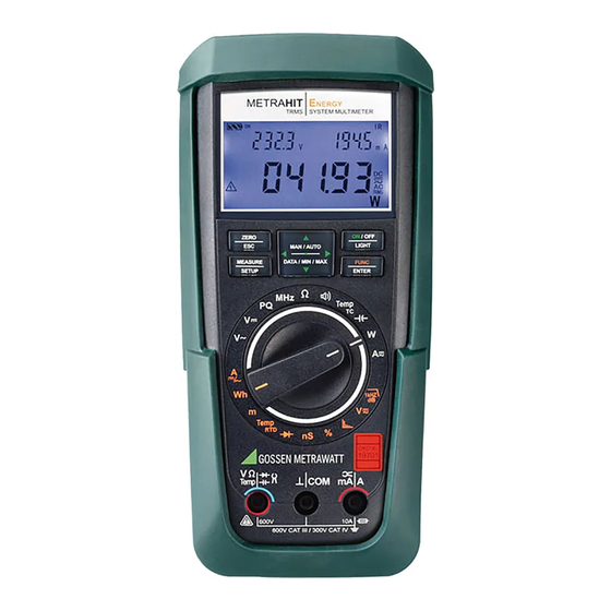
- Page 1 Operating Instructions METRAHITE NERGY 3-349-576-03 TRMS System Multimeter 3/9.11...
- Page 2 Standard Equipment – Contact Persons Scope of Delivery Function 1 TRMS system multimeter METRAHIT ENERGY (M249A) Continuity test 1 KS29 measurement cable set (Z229A) where I = 1 mA CONST 2 Batteries Diode test 1 Condensed operating instructions where I = 1 mA CONST 1 CD ROM (with operating instructions, data sheet and more)
- Page 3 Standard Equipment – Contact Persons Accessories (sensors, plug inserts, adapters, consumable materials) Product Support The accessories available for your instrument are checked for Technical queries compliance with currently valid safety regulations at regular inter- (use, operation, software registration) vals, and are amended as required for new applications. Currently If required please contact: up-to-date accessories which are suitable for your measuring GMC-I Messtechnik GmbH...
- Page 4 Standard Equipment – Contact Persons Recalibration Service Competent Partner Our service center calibrates and recalibrates (e.g. after one year as GMC-I Messtechnik GmbH is certified in accordance with part of your test equipment monitoring system, prior to use etc.) DIN EN ISO 9001:2000. all instruments from GMC-I Messtechnik GmbH and other manu- Our DKD calibration laboratory is accredited by the Deutscher facturers, and offers free test equipment management.
-
Page 5: Table Of Contents
Table of Contents Contents Page Contents Page Safety Features and Precautions ........7 Measurements ..............25 Use for Intended Purpose ..............9 Voltage Measurement ..............25 Meanings of Danger Symbols ............9 5.1.1 Direct Voltage, Pulsating Voltage and Crest Factor Measurement Meanings of Acoustic Warning Signals .......... - Page 6 Table of Contents Contents Page Contents Page Querying Parameters – InFo Menu (as moving letters) ....63 (KS17-2 safety cable set included with instrument) ......89 Entering Parameters – SETUP Menu ..........64 10.3 NA X-TRA Power Pack (Z218G: not included) ........89 6.4.1 SYSTEM Submenu .................64 10.4 PMA 16 Power Measuring Adapter (Z228A: not included) ....90 6.4.2 EVEntS Submenu ................65 10.5 Interface Accessories (not included) ..........90...
-
Page 7: Safety Features And Precautions
Safety Precautions Safety Features and Precautions Hazardous contact voltages are not detected when the ohm or capacitance measurement is selected. You have selected an instrument which provides you with high If the instrument switches itself off in the event that hazardous levels of safety. - Page 8 Safety Precautions • Maximum permissible voltage • The multimeter may only be operated with installed batteries or re- between the voltage measuring sockets or all connector sock- chargeable batteries. Dangerous currents and voltages are otherwise ets and ground is 600 V for measuring category III and 300 V not indicated, and the instrument may be damaged.
-
Page 9: Use For Intended Purpose
Safety Precautions 1.1 Use for Intended Purpose 1.2 Meanings of Danger Symbols • The multimeter is a portable device which can be held in the hand during the performance of measurements. Warning concerning a source of danger • Only those types of measurements described in section 5 may (attention: observe documentation!) be performed with the measuring instrument. -
Page 10: Operating Overview - Connections, Keys, Rotary Switch, Symbols
Operating Overview – Connections, Keys, Rotary Switch, Symbols Operating Overview – Connections, Keys, Rotary Switch, Symbols 1 Display (LCD) (see page 12 for significance of symbols) 2 MAN/AUTO: shift key for manual/automatic measuring range selection sec. 7 Increase parameter values sec. - Page 11 Operating Overview – Connections, Keys, Rotary Switch, Symbols Symbols Used in the Digital Display 1 Battery level indicator 2 ON: continuous operation (automatic shutdown deactivated) 3 DATA: display memory, “freeze measured value” 4 STORE: memory mode active 5 TRIG: synchronized storage 6 FILTER: low-pass filter active 7 EVENTS: events measurement 8 IR: infrared interface indicator...
- Page 12 Operating Overview – Connections, Keys, Rotary Switch, Symbols Symbols and Functions for Rotary Switch Positions (MD: main display, AD: auxiliary display, MR: measuring range) Switch FUNC Display Measuring function Sub-Function V~AC TRMS / HZ CLiP=OFF: alternating voltage, AC TRMS, full bandwidth DATA/MIN/MAX, MAN/AUTO, ZERO A~AC TRMS (0/2)
- Page 13 Operating Overview – Connections, Keys, Rotary Switch, Symbols User Interface Symbols in the Following Sections Scroll through main menu EC mark of conformity Scroll through submenu Select decimal point Position of the infrared interface, window on the top of the ...
-
Page 14: Initial Start-Up
Initial Start-Up – Setup Initial Start-Up Display Illumination After the instrument has been switched on, background illumina- 3.1 Inserting Batteries or Rechargeable Batteries tion can be activated by briefly pressing the ON / OFF | LIGHT key. Be certain to refer to section 9.2 regarding correct battery Illumination is switched back off by once again pressing the same installation. -
Page 15: Switching The Instrument Off
Initial Start-Up – Setup 3.4 Switching the Instrument Off Switching the Instrument Off Manually / OFF Ð Press the ON / OFF | LIGHT key until 0FF appears at the display. LIGHT 8.8.8.8.8 Shutdown is acknowledged with a brief acoustic signal. If hazardous contact voltage has been detected (HV symbol appears), the instrument cannot be switched off. -
Page 16: Control Functions
Control Functions Control Functions If the instrument switches itself off in the event that hazardous contact voltage is applied (during memory mode operation with 4.1 Selecting Measuring Functions and Measuring Ranges large sampling period), the high-voltage warning symbol remains The rotary switch is linked to an automatic socket blocking mech- visible at the display. -
Page 17: Peak Value Monitoring For Automatic And Manual Measuring Range Selection
Control Functions The instrument is automatically returned to automatic range current values in the case of automatic measuring range selection selection when the MAN / AUTO key is pressed, the rotary switch is and then to lock in the resulting measuring ranges by pressing the activated or the instrument is switched off and back on again. -
Page 18: Quick Measurements (Man Or Data Function)
Control Functions 4.1.4 Quick Measurements (MAN or DATA function) 4.2 Zero Offset / Relative Measurements – ZERO/Delta REL Function Measurements performed using a suitable fixed measuring range Zero offset or a reference value for relative measurements can be are executed more quickly than those which utilize automatic stored to memory depending upon deviation from the zero point: range selection. -
Page 19: Display (Lcd)
Control Functions Setting the Reference Value 4.3 Display (LCD) Ð Plug the measurement cables into the instrument and measure Measured Value, Unit of Measure, Type of Current, Polarity a reference value (max. 25,000 digits, or 5000 digits in 10 A The measured value with decimal and plus or minus sign appears range) at the digital display. -
Page 20: Measured Value Storage: Data (Auto-Hold / Compare)
Control Functions 4.4 Measured Value Storage: DATA (auto-hold / compare) V, A, Hz dB, F, MHz, % An individual measured value can be automatically “frozen” with 100% of measuring range 60,000 the DATA function (auto-hold). This is useful, for example, when Digits contacting the measuring points with the test probes requires your full attention. -
Page 21: Saving Minimum And Maximum Values - Min/Max Function
Control Functions Example Response from Instrument The voltage measuring range is set manually to 6 V. The first mea- Data/ Display sured value is 3 V and is stored to memory because it is greater Acous Min-Max Min. and Max. Min/Max than 10% of the measuring range (6000 digits = 0.6 V), and is Digital... -
Page 22: Measurement Data Recording - Memory Mode Operation, Store Menu Function
Control Functions 4.5 Measurement Data Recording – Memory Mode Operation, STORE Preparing for Recording – Parameter Settings Menu Function Ð First set the sampling rate for memory mode operation (see The system multimeter is capable of recording measurement data section 6.4 the rAtE parameter). using an adjustable sampling rate for long periods of time in the Ð... - Page 23 Control Functions Querying Memory Occupancy Note Memory occupancy can be queried during recording with the The StorE > StArt and StorE > CLEAr menu functions can help of the “1nFo” menu (see also section 6.3). only be selected a long as memory is not completely full Memory occupancy range: 000.1% to 099.9%.
-
Page 24: Rapid Momentary Value Acquisition For U Dc And I Dc
Control Functions 4.5.1 Rapid Momentary Value Acquisition for U DC and I DC 4.5.2 Power and Energy Measurement in the Memory Mode Rapid momentary value acquisition is only activated during mem- The value selected for the SEt > EnErGY > StorE menu parameter ory mode operation in the U DC and I DC functions, and only after specifies which values from power and energy measurements will selecting a sampling period of 0.5, 1, 2, 5, 10, 20 or 50 ms: All... -
Page 25: Measurements
– MHz/% – /nS/R Measurements: V/Hz/dB – PQ/ – – Temp – /m – W/Wh – A/Hz/thd Measurements • Be aware of the fact that dangerous voltage spikes are not displayed during measurement with the low-pass filter. 5.1 Voltage Measurement We recommend measuring voltage without the low-pass filter first, in Notes Regarding Voltage Measurement order to be able to detect any dangerous voltages. -
Page 26: Direct Voltage, Pulsating Voltage And Crest Factor Measurement - V Dc, V (Dc+Ac) And Cf
– MHz/% – /nS/R Measurements: V/Hz/dB – PQ/ – – Temp – /m – W/Wh – A/Hz/thd 5.1.1 Direct Voltage, Pulsating Voltage and Crest Factor Measurement – V DC, V (DC+AC) and CF CL ip = 0FF ! Note 20, 0 00 Set the CL iP parameter to 0FF in the current clamp setup menu. - Page 27 – MHz/% – /nS/R Measurements: V/Hz/dB – PQ/ – – Temp – /m – W/Wh – A/Hz/thd Note 60 mV range: Thermovoltages occur in the event of temperature fluctua- tion, which appear as additional voltage offset. It may be necessary to repeat zero offsetting in order to achieve the specified degree of accuracy.
- Page 28 – MHz/% – /nS/R Measurements: V/Hz/dB – PQ/ – – Temp – /m – W/Wh – A/Hz/thd Events Recording “EVEntS” Events recording can be activated with DC or AC coupling in the V DC switch position. The auto-ranging function is deactivated, CL ip = 0FF ! and the respective valid measuring range must be selected manu- ally in the left-hand auxiliary display.
- Page 29 – MHz/% – /nS/R Measurements: V/Hz/dB – PQ/ – – Temp – /m – W/Wh – A/Hz/thd Selecting the Measurement Note Ð In accordance with the voltage to be measured, turn the rotary 1 ms sampling is executed with reduced resolution and switch to V or V .
-
Page 30: Alternating Voltage And Frequency Measurement V Ac And Hz With Selectable Low-Pass Filter, V Ac + Filter And Db V Ac
– MHz/% – /nS/R Measurements: V/Hz/dB – PQ/ – – Temp – /m – W/Wh – A/Hz/thd 5.1.2 Alternating Voltage and Frequency Measurement V AC and Hz Frequency Measurement with Selectable Low-Pass Filter, V AC + FILTER and dB V AC Signal frequency appears at the left-hand auxiliary display when the instrument executes alternating voltage measurements. - Page 31 – MHz/% – /nS/R Measurements: V/Hz/dB – PQ/ – – Temp – /m – W/Wh – A/Hz/thd The active low-pass filter is indicated by the FILTER display. The multimeter is automatically switched to manual measuring range CL ip = 0FF ! 050.00 selection.
- Page 32 – MHz/% – /nS/R Measurements: V/Hz/dB – PQ/ – – Temp – /m – W/Wh – A/Hz/thd Alternating Voltage Level Measurement (dB) The default setting for the reference level is 0 dB = 0.775 V (1 mW to 600 ). This value van be adjusted in the “SET” menu (see also Voltage level measurement is used in order to ascertain overall attenuation or boosting of section 6.4):...
-
Page 33: Mains Monitoring / Mains Disturbance Recording - Pq
– MHz/% – /nS/R Measurements: V/Hz/dB – PQ/ – – Temp – /m – W/Wh – A/Hz/thd 5.1.3 Mains Monitoring / Mains Disturbance Recording – PQ Acquirable Mains Disturbances The following types of disturbances are recorded: Overview • Undervoltage (LoVoLt) and overvoltage (HiVoLt) with start time, The METRAHIT ENERGY is equipped with an operating mode for duration and extreme value. - Page 34 – MHz/% – /nS/R Measurements: V/Hz/dB – PQ/ – – Temp – /m – W/Wh – A/Hz/thd Parameters Configuration Prior to mains analysis, the function’s parameters have to be confi- Type of Measuring Resolu- Intrinsic Uncertainty Pulse Time gured under SET > MAinS. The following parameters are available: Disturbance Range tion...
-
Page 35: Mains Disturbance Recording In Memory Mode Operation
– MHz/% – /nS/R Measurements: V/Hz/dB – PQ/ – – Temp – /m – W/Wh – A/Hz/thd 5.1.4 Mains Disturbance Recording in Memory Mode Operation If memory mode operation is started (see STORE menu function above), further data in addition to those which appear at the dis- play are saved to memory, allowing for computer aided visual assessment: •... -
Page 36: Harmonic Analysis (Voltage Measurement)
– MHz/% – /nS/R Measurements: V/Hz/dB – PQ/ – – Temp – /m – W/Wh – A/Hz/thd 5.1.5 Harmonic Analysis (voltage measurement) Prerequisites The results of harmonic analysis are only valid if the following In the switch positions for the mains quality analysis and cur- conditions are fulfilled: rent measurement (A) functions, harmonic analysis is performed... - Page 37 – MHz/% – /nS/R Measurements: V/Hz/dB – PQ/ – – Temp – /m – W/Wh – A/Hz/thd Event Number of Start 26:04:10 280.1 000.002 mains 000001 14:31:10 duration* events time trans Event Event Momentary value type measured value TRMS TRMS TRMS FUNC Event selection...
-
Page 38: Frequency And Duty Cycle Measurement
– MHz/% – /nS/R Measurements: V/Hz/dB – PQ/ – – Temp – /m – W/Wh – A/Hz/thd 5.1.6 Frequency and Duty Cycle Measurement Ð Set the rotary switch to MHz or %. Ð Connect the measurement cables as shown. 1.0323 Make sure that a current measuring range (“A”) has not been acti- vated when the multimeter is connected for frequency or duty cycle measurement! -
Page 39: Resistance, Conductivity And Low-Resistance Measurement
– MHz/% – /nS/R Measurements: V/Hz/dB – PQ/ – – Temp – /m – W/Wh – A/Hz/thd 5.2 Resistance, Conductivity and Low-Resistance Measurement Ð Disconnect supply power from the electrical circuit of the de- vice to be measured, and discharge all high-voltage capaci- tors. -
Page 40: Conductivity Measurement
– MHz/% – /nS/R Measurements: V/Hz/dB – PQ/ – – Temp – /m – W/Wh – A/Hz/thd 5.2.1 Conductivity Measurement Limit Value for Low-Resistance Measurement In the event of a measured value which exceeds the selected limit Conductivity measurement works within a range of 15 to 600 nS. value, the system multimeter generates a continuous acoustic sig- “ur”... -
Page 41: Continuity Test With Constant Current Of 1 Ma
– MHz/% – /nS/R Measurements: V/Hz/dB – PQ/ – – Temp – /m – W/Wh – A/Hz/thd 5.3 Continuity Test with Constant Current of 1 mA Ð Disconnect supply power from the electrical circuit of the de- vice to be measured, and discharge all high-voltage capaci- tors. -
Page 42: Diode Testing With Constant Current Of 1 Ma
– MHz/% – /nS/R Measurements: V/Hz/dB – PQ/ – – Temp – /m – W/Wh – A/Hz/thd 5.4 Diode Testing with Constant Current of 1 mA Ð Disconnect supply power from the electrical circuit of the de- vice to be measured, and discharge all high-voltage capaci- 000.8 tors. -
Page 43: Temperature Measurement
– MHz/% – /nS/R Measurements: V/Hz/dB – PQ/ – – Temp – /m – W/Wh – A/Hz/thd Ð Connect the sensor to the two accessible jacks. The instru- 5.5 Temperature Measurement ment displays the measured temperature using the selected Temperature measurement is performed with a type K thermo- couple or a type Pt100 or Pt1000 resistance sensor (accessory, unit of measure. -
Page 44: Measurement With Resistance Sensors
– MHz/% – /nS/R Measurements: V/Hz/dB – PQ/ – – Temp – /m – W/Wh – A/Hz/thd 5.5.2 Measurement with Resistance Sensors Ð Set the rotary switch to “Temp ” or “Temp ”. Temp 1. 22.4 The last selected temperature measurement or last selected tem- 0023 perature sensor, i.e. -
Page 45: Measuring Capacitance And Cable Length In Km
– MHz/% – /nS/R Measurements: V/Hz/dB – PQ/ – – Temp – /m – W/Wh – A/Hz/thd 5.6 Measuring Capacitance and Cable Length in km Ð Disconnect supply power from the electrical circuit of the de- vice to be measured, and discharge all high-voltage capaci- 20.00 tors. -
Page 46: Cable Length Measurement In M
– MHz/% – /nS/R Measurements: V/Hz/dB – PQ/ – – Temp – /m – W/Wh – A/Hz/thd 5.6.1 Cable Length Measurement in m Note In the cable length measuring mode, the instrument calculates When measuring cable length, make sure that the cable length as a function of the capacitance value entered by the user: parameters (e.g. -
Page 47: Measurement Of Active, Apparent And Reactive Power - W, Va, Var
– MHz/% – /nS/R Measurements: V/Hz/dB – PQ/ – – Temp – /m – W/Wh – A/Hz/thd 5.7 Measurement of Active, Apparent and Reactive power – W, VA, VAr Significance of the Power Factor 1: no phase shifting Measurement of Active, Apparent and Reactive Energy – Wh, VAh, VArh The METRAHIT ENERGY is a compact power meter for direct and –(0 ... - Page 48 – MHz/% – /nS/R Measurements: V/Hz/dB – PQ/ – – Temp – /m – W/Wh – A/Hz/thd Use current clamp transformers Measurement of Active, Apparent and Reactive Power, and Power Factor – W, VA, VAr, PF only. Power measurement is not Temp possible with current clamp sen- 000.0...
- Page 49 – MHz/% – /nS/R Measurements: V/Hz/dB – PQ/ – – Temp – /m – W/Wh – A/Hz/thd Measurement of Momentary, Minimum and Maximum Values for Active, Reactive and Apparent Power pf: 0.00 000.0 000.0 000.0 000.0 Momentary Values TRMS TRMS TRMS μ...
- Page 50 – MHz/% – /nS/R Measurements: V/Hz/dB – PQ/ – – Temp – /m – W/Wh – A/Hz/thd Measurement of Active, Apparent and Reactive Energy – Wh, VAh, VArh Mean Power Values The instrument can be switched back and forth between energy Mean power consumption can be displayed by pressing the DATA/ and power measurement by pressing the FUNC | ENTER key.
- Page 51 – MHz/% – /nS/R Measurements: V/Hz/dB – PQ/ – – Temp – /m – W/Wh – A/Hz/thd Measurement of Energy Values, and Mean Power Values for Active, Reactive and Apparent Power FUNC energy energy 00:00:00 energy 00:00:00 00:00:00 W>Wh ENTER VArh Energy Values TRMS...
-
Page 52: Current Measurement
– MHz/% – /nS/R Measurements: V/Hz/dB – PQ/ – – Temp – /m – W/Wh – A/Hz/thd 5.8 Current measurement Notes Regarding Current Measurement Scope of Functions, Current Measurement, Direct Connection • The multimeter may only be operated with installed batteries or re- Function Switch Position Measuring Range... -
Page 53: Direct Current Measurement
– MHz/% – /nS/R Measurements: V/Hz/dB – PQ/ – – Temp – /m – W/Wh – A/Hz/thd Ð Switch supply power to the measuring circuit back on (3). 5.8.1 Direct Current Measurement Ð Read the display. Make a note of the measured value if the in- Measurement of Pulsating, Direct and Alternating Current, and Frequency A (DC+AC), A DC and A AC/Hz Direct, and Total Harmonic Distortion strument is not being operated in the memory mode or the... - Page 54 – MHz/% – /nS/R Measurements: V/Hz/dB – PQ/ – – Temp – /m – W/Wh – A/Hz/thd Harmonic Analysis – Total Harmonic Distortion THD With 32 sampled values per mains period (16.7; 50; 60 or 400 Hz can be selected in the menu), harmonic analysis is executed approximately once per second.
- Page 55 – MHz/% – /nS/R Measurements: V/Hz/dB – PQ/ – – Temp – /m – W/Wh – A/Hz/thd CL ip = 0ff Cf: 01.0 24.6° C Crest factor CF: 1 ... 11% TRMS μ I > 10 A FUNC Current measurement may only be performed ENTER I >...
-
Page 56: Current Measurement With Current Clamp Sensor
– MHz/% – /nS/R Measurements: V/Hz/dB – PQ/ – – Temp – /m – W/Wh – A/Hz/thd 5.8.2 Current Measurement with Current Clamp Sensor [PQ] Voltage/Current Transformer Output When a current clamp sensor is connected to the system multime- ter (V input), all current displays appear with the correct value in 1kHz accordance with the selected transformation ratio. - Page 57 – MHz/% – /nS/R Measurements: V/Hz/dB – PQ/ – – Temp – /m – W/Wh – A/Hz/thd Alternating Current Measurement with Current Clamp Sensor – A AC and Hz Harmonic Analysis with Current Clamp Sensor – thd and A AC CL ip ...
-
Page 58: Current Measurement With Current Clamp Transformer
– MHz/% – /nS/R Measurements: V/Hz/dB – PQ/ – – Temp – /m – W/Wh – A/Hz/thd 5.8.3 Current Measurement with Current Clamp Transformer Trans. Ratio DMM Measuring Range Clamp Types Alternating Current Measurement and Total Harmonic Distortion, CL IP 60 mA AC 600 mA AC 6 A AC... - Page 59 – MHz/% – /nS/R Measurements: V/Hz/dB – PQ/ – – Temp – /m – W/Wh – A/Hz/thd CLiP = 1:1/10/100/1000 000.00 1:1000 TRMS Current measurement FUNC Fundam. harmonic: 1 harmonic may only be performed ENTER with installed batteries! HArM:1 RMS value of the harm:1 00.0 HArM...
-
Page 60: Device And Measuring Parameters
Device and Measuring Parameters Device and Measuring Parameters After repeatedly pressing the MEASURE | SETUP key (without first tur- ning the multimeter off), you can return to the last selected menu The instrument’s “SET” mode (menu mode) makes it possible to set or parameter from the measuring mode. -
Page 61: Paths To The Various Parameters
Device and Measuring Parameters 6.1 Paths to the Various Parameters Cf: 01.0 MEASURE 200 . 00 1nfo SETUP TRMS Main Menus 1nFo StorE SEnd FUNC FUNC FUNC FUNC ENTER ENTER ENTER ENTER Select / Select / Submenus / parameters Query tiMe dAtE... -
Page 62: List Of All Parameters, Main Menus And Submenus
Device and Measuring Parameters 6.2 List of all Parameters, Main Menus and Submenus Menus Page: Header Menu / Submenu Function / Switch Position Parameters 0.disp 65: 0.diSP – Show/Hide Leading Zeros SEt/SYStEM Addr 76: Configuring Interface Parameters SEt/SYStEM Interface operation APoFF 64: APoFF –... -
Page 63: Querying Parameters - Info Menu (As Moving Letters)
Device and Measuring Parameters Menus Page: Header Menu / Submenu Function / Switch Position Parameters Swell 69: SwELL and diP Limit – Trigger Thresholds for Brief Overvoltages and Undervoltages SEt/MAinS system 64: SYSTEM Submenu SEt/SYStEM tEMPintern 63: tEMP intErn – Query Reference Temperature InFo Temp TC/RTD tEMPintern 67: tEMP intErn/ExtErn –... -
Page 64: Entering Parameters - Setup Menu
Device and Measuring Parameters 6.4 Entering Parameters – SETUP Menu Addr – Set Device Address 6.4.1 SYSTEM Submenu See section 7.2 on page 76. tiME – Set Time irStb – Status of the Infrared Receiver in the Stand-By Mode Entering the correct time makes it possible to acquire measured See section 7.2 on page 76 regarding settings. -
Page 65: Events Submenu
Device and Measuring Parameters 6.4.2 EVEntS Submenu bLiGht – Disable Deactivation of Background Illumination If necessary, automatic deactivation of background illumination EVEntS – Event Counter Sampling Rate and Trigger Thresholds can be disabled with this parameter setting or via the interface. An event is recorded whenever at least one measured value has fallen short of the L-trig threshold, and subsequently at least one MEASURE... -
Page 66: General Parameters
Device and Measuring Parameters 6.4.3 General Parameters CAP – Scaling Factor for Cable Length Measurement (capacitive linear electric constant) CLiP – Set Transformation Ratio (current clamp factor) MEASURE FUNC 1nFo system MEASURE FUNC system 1nFo ... - Page 67 Device and Measuring Parameters tEMP intErn/ExtErn – Select Internal or External Reference Junction External Reference Junction: Specified Temperature MEASURE FUNC 1nFo system tEMP intern SETUP ENTER FUNC FUNC tEMP set: tEMP intern / tempextern ENTER ENTER FUNC extern set: 000 ..
-
Page 68: Energy Submenu
Device and Measuring Parameters 6.4.4 EnErGY Submenu EnErGY StorE – Scope of Stored Values for Power and Energy Measurements The StorE parameter (mode) can be used to specify which values dEMAnd tiME – Time Interval for Mean Value Generation (parameter for will be saved to memory during power and energy measurements power measurement in memory mode) when memory mode operation is active. -
Page 69: Mains Submenu
Device and Measuring Parameters 6.4.5 MAinS Submenu LoVolt and HiVolt – Trigger Thresholds You can specify the limits within which AC+DC TRMS voltage must lie in the following two displays. If these limits are exceeded or fal- MAinS – Mains Disturbance Recording Parameter len short of, a HiVolt or a LoVolt event is recorded. - Page 70 Device and Measuring Parameters PEAK LiMit – Maximum Peak Value for Measuring Voltage Steep Sloped Voltage Transients The momentary value of the applied signal is measured 1200 A trigger threshold can be specified here as an absolute value for times per second and compared with the limit selected here (inde- steep sloped voltage transients which are superimposed to mains pendent of polarity).
-
Page 71: Harm Submenu
Device and Measuring Parameters 6.4.6 HArM Submenu Note Clip factor and type are not taken into consideration for this HArM – Harmonic Analysis Parameter range selection, and the actual measuring range is selected In order to analyze the measuring signal’s harmonics, its funda- instead. -
Page 72: Store Submenu - Parameters For Memory Mode Operation
Device and Measuring Parameters 6.4.7 StorE Submenu – Parameters for Memory Mode Operation If a sampling rate is selected which is greater than auto power off time rAtE – Transmission and Storage Rate (see APoFF parameter on page 64), the instrument is switched off automatically after auto power off time has elapsed, and back on The sampling rate specifies the time interval after which the res- again roughly 10 seconds before the next measuring point. - Page 73 Device and Measuring Parameters HYSt – Hysteresis (parameter for memory mode operation) triG – Trigger Conditions for Memory Mode Operation The hysteresis setting allows for efficient use of memory space. The setting StorE > triG SEt = sto-ou / sto-in / off can be used to During memory mode operation, new measured data are only specify how measured value recording is started and stopped: saved if they deviate from the previously stored value by an...
-
Page 74: Default Settings (Factory Settings) - Reset
Device and Measuring Parameters Actual measurement is always executed using the sampling rate 6.5 Default Settings (factory settings) – Reset selected in “Store > rAtE”. Previously entered changes can be undone, and default settings can be restored. This may be advisable under the following cir- FUNC MEASURE 1nFo... -
Page 75: Interface Operation
Interface Operation Interface Operation Starting Continuous Transmission Operation with Menu Functions Your instrument is equipped with an infrared interface: Data and MEASURE FUNC FUNC 1nFo SEnd StArt send commands are transferred through the instrument housing by ENTER ENTER SETUP means of infrared light to an interface adapter (accessory) which is plugged onto the multimeter and connected to a PC via USB. -
Page 76: Configuring Interface Parameters
Interface Operation Addr – Address 7.2 Configuring Interface Parameters If several multimeters are connected to the PC via an interface adapter, a separate address can be assigned to each instrument. 1rStb – Status of the Infrared Receiver in the Stand-by Mode Address number 1 should be selected for the first instrument, 2 There are two possible switching statuses for the infrared interface should be assigned to the second and so forth. -
Page 77: Technical Data
Technical Data Technical Data Intrinsic Uncertainty under Ref. Cond. for High Resolution (59,999 digits) Resolution at Upper Input impedance Overload Capacity Meas. (... % rdg. + ... d) (... % rdg. + ... d) (... % rdg. + ... d) Range Limit Measuring Range Function... - Page 78 Technical Data Resolution at Upper Meas. Intrinsic Uncertainty under Reference Overload Capacity Measuring Range Range Limit Function Conditions for High Resolution (59,999 digits) 60,000 6,000 Value Time (... % rdg. + ... d) Discharge res. 0max — 10 pF 1 M 1 + 10 with ZERO function active 600 V...
- Page 79 Technical Data Crest Factor CF Additional error caused by the signal’s crest factor: 1,5 < CF 3 1% rdg. Measuring range: 1.0 11.0, resolution: 0.1 3 < CF 5 3% rdg. Typical (not specified) maximum deviation: CF ...
- Page 80 Technical Data Intrinsic Uncertainty and Frequency Influence for Power and Energy Additional deviation for U, I during power measurement with higher crest factor, f = 0 … 65 Hz: Measurement CF = 2: -0.3% rdg., CF = 3: -0.9% rdg., Intrinsic Uncertainty ±(...
- Page 81 Technical Data Influencing Quantities and Influence Error Influen- Measured Qty. / Intrinsic Uncertainty cing Sphere of Influence ... % rdg. + ... d) Measuring Range Influencing Sphere of Measured Quantity/ Influence Error per 10 K Quantity (...% rdg. + ... d) Quantity Influence Measuring Range...
- Page 82 Technical Data Data Interface Influencing Measured Quantity/ Type Optical via infrared light through the housing Sphere of Influence Damping Quantity Measuring Range Data transmission Serial, bidirectional (not IrDa compatible) Interference quantity max. 600 V > 120 dB Protocol Device specific Common mode , 60 V >...
- Page 83 Technical Data Power Supply Display Battery 2 each 1.5 V AA batteries, Transreflective LCD alkaline manganese per IEC LR6 panel (65 x 36 mm) (2 each 1.2 V NiMH rechargeable batteries with display of up also possible) to 3 measured values, unit of Service life With alkaline manganese: approx.
- Page 84 Technical Data Acoustic Signals Ambient Conditions For voltage Intermittent signal at above 600 V Accuracy range 0C to +40C 10C to +50C * For current Intermittent signal at above 10 A Op. temp. range T Storage temp. range 25C to +70C (without batteries) Continuous signal at above 16 A Relative humidity 40 to 75%, no condensation allowed...
-
Page 85: Maintenance And Calibration
Maintenance – Calibration Maintenance and Calibration Note Attention! Battery Replacement Disconnect the instrument from the measuring circuit before Stored measurement data are not lost when the batteries opening the battery compartment lid or fuse cover in order are replaced. The selected operating parameters remain in to replace batteries or fuses! memory, although date and time must be reentered. -
Page 86: Fuse
Maintenance – Calibration Replacing the Batteries If the fuse is blown or has not been inserted, “FuSE” appears at the digital display. The fuse interrupts the current measuring ranges. All other measuring ranges remain functional. Attention! Disconnect the instrument from the measuring circuit before opening the battery compartment lid in order to replace the batteries. -
Page 87: Housing Maintenance
Maintenance – Calibration If you use batteries or rechargeable batteries in your instrument or accessories which no longer function properly, they must be duly Attention! disposed of in compliance with the applicable national regulati- Use specified fuses only! ons. If fuses with other blowing characteristics, other current rat- Batteries or rechargeable batteries may contain harmful substan- ings or other breaking capacities are used, the operator is ces or heavy metal such as lead (PB), cadmium (CD) or mercury... -
Page 88: Manufacturer's Guarantee
Maintenance – Calibration We are pleased to perform DKD or factory calibrations for you in our calibration laboratory. Please visit our website at www.gossenmetrawatt.com ( Services DKD Calibration Center or FAQs Calibration questions and answers). By having your measuring instrument calibrated regularly, you ful- fill the requirements of a quality management system per DIN EN ISO 9001. -
Page 89: Accessories
Accessories 10 Accessories 10.1 General 10.3 NA X-TRA Power Pack (Z218G: not included) The extensive accessories available for our measuring instruments Use power packs from GMC-I Messtechnik GmbH only in combi- are checked for compliance with currently valid safety regulations nation with your instrument. -
Page 90: Pma 16 Power Measuring Adapter (Z228A: Not Included)
Accessories 10.4 PMA 16 Power Measuring Adapter (Z228A: not included) 10.5 Interface Accessories (not included) The PMA 16 power measuring adapter is an intermediate plug for USB X-TRA Bidirectional Interface Adapter (Z216C) safe, trouble-free measurement of power consumption of single- E series METRAHIT multimeters which are equipped with a serial phase consumers connected by means of a plug. - Page 91 Accessories GMC-I Messtechnik GmbH...
-
Page 92: Glossary - Abbreviations Of Measuring Functions And Measuring Parameters With Their Meanings
Glossary 11 Glossary – Abbreviations of Measuring Functions and Measuring Parameters with their Meanings Descriptions of the following measuring functions and their use Descriptions of device parameters and their settings (which are are included in section 5. Descriptions of the following measuring not listed here) are included in section 6. - Page 93 Glossary Abbreviation Meaning General Description Application Switch (Sub) Menu Description Specifically for this Instrument Chapter / Page Position / Parameter Menu EVEntS Submenu for events An event is recorded whenever at least one measured value has fallen short of the L-trig threshold Events recording recording parameters for at least one second, and subsequently at least one measured value has exceeded the H-trig...
- Page 94 Glossary Abbreviation Meaning General Description Application Switch (Sub) Menu Description Specifically for this Instrument Chapter / Page Position / Parameter Menu L_triG Lower trigger threshold See StorE Selective memory mode operation StorE menu section 4.5 > triG MAinS Submenu for power Parameters: Power disturbance disturbance analysis...
- Page 95 Glossary Abbreviation Meaning General Description Application Switch (Sub) Menu Description Specifically for this Instrument Chapter / Page Position / Parameter Menu StorE Main memory for Parameters: HYSt, rAtE, Sto-ou, Sto-in, L_triG, H_triG, t.StorE Memory mode memory mode operation StorE menu operation Power and energy measurement in memory mode: section 4.5.2...
-
Page 96: Index
Index 12 Index Current ............53 0.diSP Interfaces ..............65 Voltage ............27 Accessories ..........90 Current Clamp Sensor ........56, 57 States ............11 Active Power Current Measurement ............47 irStb ...............76 Addr Notes ..............76 ............52 APoFF Scope of Functions .............. - Page 97 Index OCCUP Safety Precautions Use for Intended Purpose ..............63 ..........7 ........9 Overview Sampling Rate (rAtE parameter) ......72 Keys and Connections Scaling Factor ........ 10 ............46 vErSion ..............63 Parameters Scope of Delivery ..........62 ............2 Voltage Comparator ..........31 Overvoltage Setting the Reference Value ............
- Page 98 Edited in Germany · Subject to change without notice · PDF version available on the Internet GMC-I Messtechnik GmbH Südwestpark 15 90449 Nürnberg, Germany...
Need help?
Do you have a question about the METRAHIT ENERGY TRMS System Multimeter and is the answer not in the manual?
Questions and answers